Necta Snakky Service manual

INSTALLATION, USE AND MAINTENANCE MANUAL
UK English
Snakky Max
DOC. NO. H 239U 00
EDITION 1 2004-07


Italiano Si dichiara che la macchina, descritta nella targhetta di identicazione, è
conforme alle disposizioni legislative delle Direttive Europee elencate a lato e suc-
cessive modiche ed integrazioni.
English The machine described in the identication plate conforms to the legisla-
tive directions of the European directives listed at side and further amendments and
integrations
English The harmonised standards or technical specications (designations) which
comply with good engineering practice in safety matters in force within the EU have
been applied are:
Français La machine décrite sur la plaquette d’identication est conforme aux
dispositions légales des directives européennes énoncées ci-contre et modications
et intégrations successives
Español Se declara que la máquina, descrita en la etiqueta de identicación, cum-
ple con las disposiciones legislativas de las Directrices Europeas listadas al margen
y de sus sucesivas modicaciones e integraciones
Português Declara-se que a máquina, descrita na placa de identicação está con-
forme as disposições legislativas das Diretrizes Européias elencadas aqui ao lado e
sucessivas modicações e integrações
Deutsch Das auf dem Typenschild beschriebene Gerät entspricht den rechts aufge-
führten gesetzlichen Europäischen Richtlinien, sowie anschließenden Änderungen
und Ergänzungen
Nederlands De machine beschreven op het identicatieplaatje is conform de
wetsbepalingen van de Europese Richtlijnen die hiernaast vermeld worden en latere
amendementen en aanvullingen
Italiano Le norme armonizzate o le speciche tecniche (designazioni) che sono
state applicate in accordo con le regole della buona arte in materia di sicurezza in
vigore nella UE sono:
Français Les normes harmonisées ou les spécications techniques (désignations)
qui ont été appliquées conformément aux règles de la bonne pratique en matière de
sécurité en vigueur dans l’UE sont :
Deutsch Die harmonisierten Standards oder technischen Spezikationen (Bestim-
mungen), die den Regeln der Kunst hinsichtlich den in der EU geltenden Sicherheits-
normen entsprechen, sind:
Español Las normas armonizadas o las especicaciones técnicas (designaciones)
que han sido aplicadas de acuerdo con las reglas de la buena práctica en materia de
seguridad vigentes en la UE son:
Português As normas harmonizadas ou as especicações técnicas (designações)
que foram aplicadas de acordo com boas regras de engenharia em matéria de seg-
urança em vigor na UE são:
Nederlands De geharmoniseerde normen of technische specicaties (aanwijzingen)
die toegepast werden volgens de in de EU van kracht zijnde eisen van goed vakman-
schap inzake veiligheid zijn de volgende:
DICHIARAZIONE DI CONFORMITA’
DECLARATION OF CONFORMITY
DÉCLARATION DE CONFORMITÉ
KONFORMITÄTSERKLÄRUNG
DECLARACIÓN DE CONFORMIDAD
DECLARAÇÃO DE CONFORMIDADE
VERKLARING VAN OVEREENSTEMMING
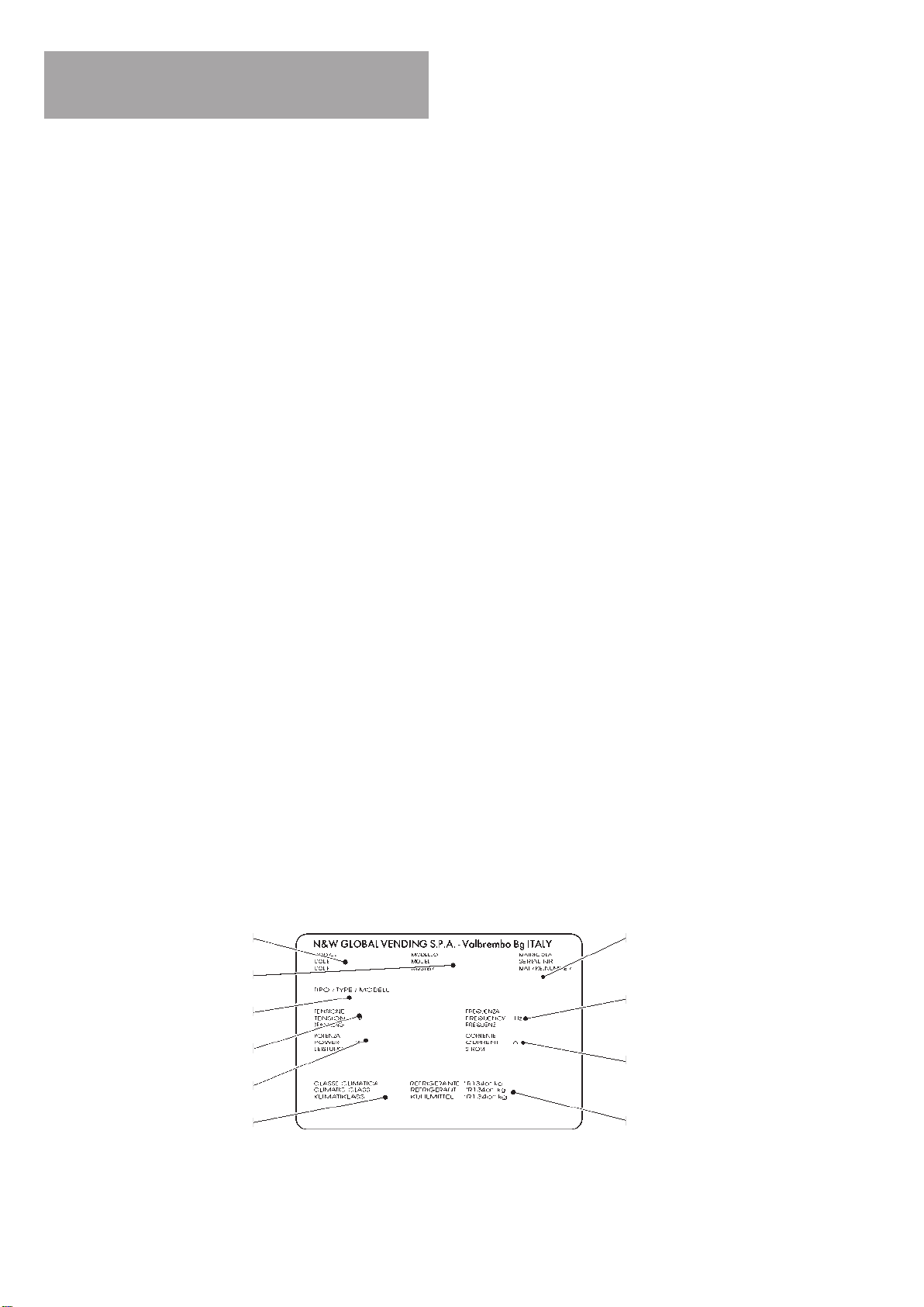
Targhetta di identicazione
Identication label
Valbrembo, 01/01/2012
ANDREA ZOCCHI
C.E.O
Direttive europee
European directives
Sostituita da
Repealed by
2006/42/EC
73/23/EC + 93/68/CE 2006/95/CE
89/336/EC + 92/31/CE +
93/68/CE
2004/108/EC
90/128/EC 2002/72/CE
80/590/EEC and 89/109/
EEC
EC 1935/2004
EC 10/2011
2002/96/EC
Norme armonizzate /
Speciche tecniche
Harmonised standards
Technical specica-
tions
EN 60335-1:2002 + A1:2004 + A11:2004 + A12:2006
+ A2:2006+ A13:2008
EN 60335-2-75:2004 + A1:2005 + A11:2006 +
A2:2008 + A12:2010
EN 62233:2008
EN 55014-1: 2006 + A1: 2009
EN 55014-2: 1997 + A1: 2001 + A2: 2008
EN 61000-3-2: 2006 + A1: 2009 + A2: 2009
EN 61000-3-3: 2008
EN 61000-4-2: 2009
EN 61000-4-3: 2006 + A1: 2008
EN 61000-4-4: 2004
EN 61000-4-5: 2006
EN 61000-4-6: 2009
EN 61000-4-11: 2004
Il fascicolo tecnico è costituito presso:
The technical le is compiled at:
N&W GLOBAL VENDING S.p.A.

Declaration of conformity
The declaration of conformity with the European Direc-
tives and Standards provided for by the laws in force
is supplied by the rst page of this manual, which is an
integral part of the machine.
It is declared that the machine described by
the identication plate is in compliance with the
provisions of the European Directives, its sub-
sequent amendments and integrations as well as with
the harmonised standards or technical specications
(designations) applied in compliance with the safety
rules of good practice enforced in the EU and listed on
the same page.
Warnings
f o r u s e
The machine can be used by children and by people
having reduced physical, sensorial or mental skills under
the supervision of people responsible for their safety or
specically trained on the use of the machine. Children
shall be prevented from playing with the machine by the
people in charge of their supervision.
f o r s c r a p p i n g
The symbol shows that the machine can not
be disposed of as common waste, but it must
be disposed of as it is established by the
2002/96/CE (Waste Electrical and Electronics
Equipments - WEEE) European Directive and
by the national laws arising out of it in order to prevent
any negative consequence for environment and human
health.
The dierentiated collection of the machine at the end of
its life is organised and managed by the manufacturer.
For the correct disposal of the machine contact the sales
point where you have purchased the machine or our
after-sales service.
The unlawful disposal of the machine implies the appli-
cation of the administrative sanctions provided for by the
rules in force.
Attention!
If the machine is equipped with a cooling system, the
cooling unit contains HFC-R134a uoridised greenhouse
eect gas ruled by the Kyoto protocol, the total heating
potential of which is equal to 1300.

1
© by NECTA VENDING SOLUTIONS SpA 0407 239 - 00
TABLE OF CONTENTS
English
INTRODUCTION PAGE 2
IDENTIFICATION OF THE VENDING MACHINE PAGE 2
IN THE EVENT OF FAILURES PAGE 2
TRANSPORT AND STORAGE PAGE 2
USING THE VENDING MACHINE PAGE 3
POSITIONING THE VENDING MACHINE PAGE 3
WARNING FOR INSTALLATION PAGE 3
PRECAUTIONS IN USING THE MACHINE PAGE 3
WARNING FOR SCRAPPING PAGE 3
TECHNICAL SPECIFICATIONS PAGE 4
ACCESSORIES PAGE 4
POWER CONSUMPTION PAGE 4
CHANGEABLE COMBINATION LOCK PAGE 5
LOADING AND CLEANING PAGE 6
MAIN SWITCH PAGE 6
CONFIGURING THE SPIRALS PAGE 6
HYGIENE AND CLEANING PAGE 7
LOADING PRODUCTS PAGE 7
START-UP PAGE 8
NOISE LEVEL PAGE 8
INSTALLATION PAGE 9
UNPACKING THE VENDING MACHINE PAGE 9
INSTALLING THE PAYMENT SYSTEM PAGE 9
CONNECTION TO THE POWER SUPPLY PAGE 10
CONTROLS AND INFORMATION PAGE 10
INTERNAL COMPONENTS PAGE 11
MAIN SWITCH PAGE 11
DISPENSING COMPARTMENT
MANUAL RELEASE PAGE 11
OPERATING MODES PAGE 12
USER INTERFACE PAGE 12
DIRECT SELECTIONS PAGE 12
NORMAL OPERATING MODE PAGE 12
FILLER MENU PAGE 12
STATISTICS PAGE 13
PRICES BY SINGLE SELECTIONS PAGE 13
CHANGE TUBES CONTROL PAGE 13
SPECIAL SELECTIONS PAGE 13
TEST PAGE 14
GSM PRE-ALARMS PAGE 14
EVADTS TRANSFER PAGE 14
TECHNICIAN MENU PAGE 15
PRESENT FAILURES PAGE 16
PROGRAMMING THE PARAMETERS PAGE 17
STATISTICS PAGE 22
TEST PAGE 23
MACHINE INFORMATION PAGE 24
GSM PAGE 24
MAINTENANCE PAGE 25
PRINTED BOARD FUNCTIONS
AND INDICATOR LAMPS PAGE 25
CONFIGURING THE BOARD PAGE 25
SOFTWARE UPDATE PAGE 25
CONFIGURINGTHETRAYS PAGE 26
PRODUCT SPACERS PAGE 26
PRODUCT EJECTOR PAGE 26
REPLACING THE SPIRALS PAGE 26
REMOVING THE TRAYS PAGE 26
CHANGING THE NUMBER OF TRAYS PAGE 27
CHANGING THE TRAY CONFIGURATION PAGE 27
POWER SUPPLY UNIT PAGE 28
ACCESS TO THE COOLING UNIT PAGE 28
PROGRAMMING MENU - SUMMARY PAGE 31
WIRING DIAGRAM PAGE 58

INTRODUCTION
This technical documentation is part and parcel of
the machine and must always follow the machine in
case it is moved or ownership is transferred, so as
to allow consultation by dierent operators.
Before starting installation and using the machine, it is
rst necessary to carefully read and understand the in-
structions contained in this manual, as they oer impor-
tant information on installation safety, operating instruc-
tions and maintenance.
Th i s m a n u a l is d i v i d e d i n T o T h r e e c h a p T e r s .
The rst chapter describes the loading and routine
maintenance operations which are carried out in areas of
the machine accessible with simple use of the door key,
without using any other tools.
The second chapter contains the instructions for cor-
rect installation and all information necessary for opti-
mum use of the machine.
The third chapter describes maintenance operations
which involve the use of tools to access potentially dan-
gerous areas.
The operations described in the second and third chap-
ters must be carried out only by personnel who have the
specic knowledge of the machine functioning from a
point of view of electrical safety and health regulations.
IDENTIFICATION OF THE VENDING
MACHINE AND ITS CHARACTERISTICS
Every machine is identied by its own serial number,
indicated on the rating plate attached inside the cabinet
on the right side.
This plate (see g. 1) is the only one acknowledged by
the manufacturer as the identication of the apparatus,
and carries all the data which readily and safely give
technical information supplied by the manufacturer. It
also assists in the spare parts management.
IN CASE OF FAILURE
In most cases, any technical problems are corrected by
small repair operations; however, before contacting the
manufacturer we recommend that this manual be read
carefully.
Should there be serious failures or malfunctions, contact
the following:
N&W GLOBAL VENDING S.p.A.
Via Roma 24
24030 Valbrembo
Italy - Tel. +39 - 035606111
TRANSPORT AND STORAGE
To prevent any damage, special care should be taken
when loading or unloading the machine.
The machine can be lifted by a motor-driven or manual
forklift truck, and the forks are to be placed underneath
the machine from the side clearly indicated by the sym-
bol on the cardboard package.
Do not:
overturn the vending machine;-
drag the vending machine with ropes or similar;-
lift the vending machine by its sides;-
lift the vending machine with slings or ropes;-
shake the vending machine.-
The machine should be stored in a dry room where the
temperature remains between 0° C and 40 °C.
Avoid stacking machines one on top of the other and
always keep it upright as indicated by the arrows on the
packing.
Refrigeration system class
Absorbed power
Operating voltage
Model
Product code
Type and amount of refrigerant gas
Current
Frequency
Serial number
Type

3
© by NECTA VENDING SOLUTIONS SpA 0407 239 - 00
USING THE VENDING MACHINE FOR
PACKAGED PRODUCTS
Adifferentsalepricecanbesetforeachproductselection
by the machine electronic control. The various functions
areprogrammedthroughtheselectionkeypadwithoutany
need for additional equipment.
Allmodels are equipped with variableconfigurationtrays,
addingorremovingdividers,spiralsandratiomotors;there-
fore the machine can be easily suited to specific needs.
All trays are preset for the operation of up to 6 selections
(maximum setting).
The product compartments are equipped with independ-
ent motors and spirals; each selection will continue its
operation autonomously even if the other selections are
disconnected.
POSITIONING THE VENDING MACHINE
The vending machine is not suitable for outdoor installa-
tion.Itmustbepositionedinadryroomwherethetempera-
tureremainsbetween5°Cand32°C,andnotwherewater
jets are used for cleaning (e.g. in large kitchens, etc.).
To ensure correct machine operation we recommend
installing the air baffle plate / spacer (80 mm) to the back
of the machine (see Fig. 2).
Warning!
Incorrectventilationmaycompromisetheproperfunc-
tioning of the cooling unit.
The machine should be positioned with a maximum incli-
nation of 2°.
Ifnecessaryprovideproperlevellingbywayoftheadjust-
able feet included.
WARNING FOR INSTALLATION
The machine installation and the following mainte-
nance operations should be carried out by qualified
personnel only, who are trained in the correct use of
the machine according to the standards in force.
The machine is sold without payment system, therefore
the installer of such a system is responsible for any
damage to the machine or to things and persons caused
byfaultyinstallation.
The integrity of the machine and compliance with the
standardsoftherelevantsystemsmustbecheckedat
least once a year by qualified personnel.
PRECAUTIONS IN USING THE MACHINE
The following precautions will assist in protecting the
environment:
- use biodegradable products only to clean the machine;
- adequately dispose of all containers of the products
used for loading and cleaning the machine;
- keep the machine away from heat sources;
- regularly check the condition of the door seal to limit
any heat dispersion;
- limit as much as possible door opening time during
loading operations to avoid temperature increase
inside the cabinet and subsequent power consumption.
WARNING FOR SCRAPPING
Wheneverthemachineistobescrapped,thelawsinforce
regarding environment protection should be strictly ob-
served. More specifically:
- ferrous and plastic materials and the like are to be
disposed of in authorized areas only;
- insulating materials should be recovered by qualified
companies;
- the gas inside the cooling unit, regardless of the type
(see the identification plate), should be recoveredby
qualified companies by means of special equipment.
Fig. 2
1 - Securing holes
2 - Spacer
3 - Fastening screws

4
© by NECTA VENDING SOLUTIONS SpA 0407 239 - 00
TECHNICAL SPECIFICATIONS
Power supply voltage 230 V~
Power supply frequency 50 Hz
Absorbed power 560 W
Max. operating conditions:
Ambient temperature 32 °C
Relativehumidity 65 %
Refrigeration system:
Compressor’s refrigeration output 620 W
Fan-forced evaporator
Programmable defrosting cycle
DIMENSIONS
Height 1830 mm
Width 740 mm
Depth 855 mm
Overall depth with door open 1350 mm
Weight 225 Kg
PAYMENT SYSTEM
Themachineissuppliedwithallelectricalprearrangement
for systems with Executive, BDV and MDB protocol, as
well as for installation of 24 V DC validators.
Beside the coin mechanism housing, suitable space is
provided for the installation (optional) of the most widely
used payment systems.
SALES PRICES
Adifferent programmable price can be set for each single
selection.
COIN BOX
Cover and lock are available as an optional feature.
CONTROLS AND SAFETY DEVICES
- Payment system compartment switch
- Timeout for power supply to dispensing motors
- Compressor overheating protection
- Line fuses
- Fuses on transformer primary and secondary windings
ACCESSORIES
A wide range of accessories can be installed on the
machine, to vary its performance.
Theinstallationkitsaresuppliedwiththeirowninstallation
and test instructions, which must be strictly observed to
ensure the machine safety.
Installationandthefollowingtestingoperationsmust
be carried out exclusively by personnel who have a
specific knowledge of the machine functions from a
point of view of electrical safety and health regula-
tions.
POWER CONSUMPTION
The machine power consumption depends on many fac-
tors, such as temperature and ventilation of the room
where it is installed, temperature of loaded products,
internal temperature of the refrigerated box.
Under average conditions, and namely:
- Ambient temperature: °C 20
- Refrigerated box temperature: °C 5
- temperature of loaded products
(machine completely empty) °C 20
the following power consumption levels resulted:
- Hourly stand-by power consumption Wh 266
The above power consumption calculated from average
data should only be taken as an indication.
Fig. 3

5
© by NECTA VENDING SOLUTIONS SpA 0407 239 - 00
CHANGEABLE COMBINATION LOCK
Some machine models are fitted with a changeable com-
bination lock.
The lock is supplied with a silver colour key to be used for
normal opening and closing.
Thelockcanbecustomisedbymeansofakit,availableas
accessory, permitting changing of the lock combination.
This kit includes a change key (black) for the current lock
combination as well as the change (gold) and use (silver)
keys for the new combination.
Setsof change andusekeyswith other combinationscan
be supplied on request.
Additional sets of use keys (silver) may be requested,
indicating the combination stamped on the keys.
Generally, only the use key (silver) is used, while the
combination change keys (gold) can be kept as spares.
Do not use the change key for normal opening, as it
may damage the lock.
Fig. 4
To change combination do as follows:
- open the machine door to avoid forcing the rotation;
- lightly lubricate the inside of the lock with a spray;
- insert the current change key (black) and rotate to the
change position (reference notch at 120°);
- remove the current change key and insert the change
key (gold) with the new combination;
- rotate to the close position (0°) and remove the change
key.
The lock will now have the new combination.
Thekeys withthe old combination cannot beused for
the new combination.

6
© by NECTA VENDING SOLUTIONS SpA 0407 239 - 00
Chapter 1
LOADING AND CLEANING
MAIN SWITCH
Whenextractingtheslidingcompartment,aspecialswitch
(see Fig. 5) disconnects the power from the machine
electrical system to allow maintenance and cleaning op-
erations in full safety.
Theonlypartsthatstayenergisedarethoseprotected
by covers and carrying a plate with the warning “dis-
connect the power before removing the cover”.
Whendispensingsticksofcandiesorsimilarproducts,itis
possibleto settherotation ofthespiralsto 180°insteadof
360° for the 75 mm compartments and use a special right
hand spiral fitted with a divider (see Fig. 7), doubling the
capacity of the compartments.
It is possible to insert a divider in the already installed
spirals (see Fig. 7).
Asstandardfeatureorusingspecialkits,themachinecan
be equipped with small compartments, suitable for dis-
pensing cans, plastic bottles up to 69 mm dia., 0.2 litre
Tetra-Paks.
The compartments equipped in this way can be recog-
nisedbytheshapeoftheproductsupportbracket(seeFig.
8).
Some bottle types can be dispensed without using the
supports.
Most bottles can be dispensed without using any special
accessories, loading the bottles up side down, so that the
CONFIGURING THE SPIRALS
Accordingtothesizeoftheproductstobedispensed,each
machine can be fitted with a variable number of trays
(maximum 7), removable partitions and with dispensing
spirals of different pitch.
Thespiralscanbehousedeitherin152mmcompartments
(two spirals, right-hand and left-hand, in each product
holder) for large size products, or into 75 mm compart-
ments (one right-hand spiral in each product holder) for
small size products.
Fig. 5
1 - Door opening grip
2 - Trays
3 - Lock
4 - Product passage photocells (optional)
5 - Product dispensing compartment
6 - Main switch
7 - Sliding compartment
Fig. 6
1 - Tray
2 - Mobile walls
3 - Right-hand spiral
4 - Left-hand spiral
Fig. 7
1 - 180° rotation spiral
2 - Divider
A - Spiral pitch
B - Maximum product size

7
© by NECTA VENDING SOLUTIONS SpA 0407 239 - 00
cap slides in the compartment channel.
The spirals can be positioned with 22,5 degree steps by
pulling them towards the front and rotating them in the
direction of ejection.
Normally, the products can be dispensed without any
problems when the spiral end is in the lower centre posi-
tion.
The maximum size (see Fig. 6) and the number of prod-
ucts,thepitchandthedirectionofrotationofthespiralsare
shown in the following table.
The machine is supplied with a table indicating the opti-
mum setting for the different product types.
Theconfigurationcanbechangedfollowingtheindications
of the relevant chapter.
HYGIENE AND CLEANING
According to current health and safety regulations, the
operator of vending machines is responsible for their
hygiene and cleaning.
The vending machine is not suitable for outdoor installa-
tion.Itmustbepositionedinadryroomwherethetempera-
tureremainsbetween5°Cand32°C,andnotwherewater
jets are used for cleaning.
This vending machine should only be used to sell and
dispensepackagedproductsthatdonotneedrefrigeration
to be preserved.
Strictly comply to the producer’s specifications regarding
storage method and expiry date for each product.
Any other use is unsuitable and thus potentially dan-
gerous.
It is advisable to use sanitising products (chlorine based
detergent or similar) to clean all surfaces even if not in
direct contact with food.
Some parts of the machine can be damaged by strong
detergents.
The manufacturer declines all responsibility for dam-
age to persons caused by the non-compliance with
current regulations.
At least every six months it is necessary to clean the
ventilation grilles of the cooling system using a vacuum
cleaner or compressed air, doing as follows:
- with the vending machine disconnected from the
power supply, remove the front grille, completely
undoing the two screws;
- remove the air intake grille.
- after cleaning the grilles, reassemble everything in the
reverse order.
A.mm B.mm °N
08676
46067
45058
642401
046311
430331
036251
420291
)°081(420291+91
Under no circumstances should sprayed water be
used.
Before any maintenance operation always switch the
machine off.
The integrity of the machine and compliance with the
standardsoftherelevantsystemsmustbecheckedat
least once a year by qualified personnel.
Fig. 8
1 - Tray groove
2 - Product support
Fig. 9
1 - Air-intake grille
2 - Front grille

8
© by NECTA VENDING SOLUTIONS SpA 0407 239 - 00
LOADING PRODUCTS
- Remove one tray at a time, lifting it and pulling it past
the retaining slide. The upper trays will tilt downwards
to facilitate loading.
Verythinproductscanbedispensedonlyusingthespecial
spacer.
Fig. 11
- Load all products starting at the front, without inserting
products with a temperature above 30°C, ensuring that
all spaces are filled. The bottom of the product must
rest at the bottom of the compartment with the label
facing the window so that it can be identified.
Allproductsshouldloadeasily,donotinsertproducts
which are too large for the space.
- Push in the trays completely, ensuring that they go
past the retaining slide.
Fig. 12
Fig. 10
The sealed end of bags may be caught under the spiral,
preventing the free fall of the product.
Fold the seal towards the front of the unit and upwards
before inserting the product in the spiral.
More fragile products must be placed on the lower
trays to prevent damage when they drop.
START-UP
Each time the machine is started the number of trays
connected to the system are checked by the electronic
controls and indicated on the display.
Also the number of actually connected compartments is
checked.
Thedisplaywillindicateinasequenceinformationregard-
ing:
- software version
- presence of dispensing detection photocells
- number of trays and compartments
- presence of dispensing compartment lock device
- internal sensor temperature.
NOISE LEVEL
The continuous, weighted equivalent acoustic pressure
level is below 70 dB.
1 - Product spacer
2 - Brackets
3 - Adjustment notches

9
© by NECTA VENDING SOLUTIONS SpA 0407 239 - 00
Chapter 2
INSTALLATION
The machine installation and the following mainte-
nance operations should be carried out by qualified
personnel only, who are trained in the correct use of
themachineandareawareofthespecificrisksofsuch
operations.
Themachineis notsuitable foroutdoorinstallation, it
mustbeinstalledinadryroomwherethetemperature
remains between 5°C and 32°C.
It cannot be positioned where water jets are used for
cleaning (e.g. in large kitchens, etc.).
The machine should be positioned with a maximum
inclination of 2°.
The relative humidity must not exceed 65%.
UNPACKING THE VENDING MACHINE
After removing the packing, ensure that the machine is
intact.
If the vending machine is found to be damaged, immedi-
ately inform the carrier and do not use the machine.
No packing elements (i.e. plastic bags, polystyrene
foam, nails, etc.) should be left within the reach of
children, as they are potentially dangerous.
Packing materials must be disposed of in authorised
containersandtherecyclableonesmustberecoveredby
qualified companies.
If the vending machine had been laid down during
transport,allowatleastone hour beforeconnectingit
to the mains.
INSTALLING THE PAYMENT SYSTEM
The machine is sold without payment system, there-
fore the installer of such a system has sole responsi-
bility for any damage to the machine or to things and
persons caused by incorrect installation.
Installthe coinmechanismpayingattention, accordingto
the type used, to:
- choose the most suitable securing holes;
- loosening the fastening screw and adjusting the coin
slot chute according to the coin mechanism opening;
- loosen the fastening screws and adjust the selector
openinglever;
- to aid installation the coin mechanism support plate
can be lifted and rotated.
Fig. 13
1 - Coin chute fastening screw
2 - Coin chute
3 - Selector opening cam
4 - Selector lever fastening screw
5 - Coin mechanism securing holes
6 - Coin mechanism compartment door
7 - Coin mechanism
8 - Coin slot chute
9 - Coin return chute

10
© by NECTA VENDING SOLUTIONS SpA 0407 239 - 00
CONNECTING THE MACHINE TO THE
POWER SUPPLY
Themachineisdesignedtooperateunderasingle-phase
230 V~ voltage and is protected by T6.3 A fuses.
Before making the connection, ensure that the rating
corresponds to that of the power grid, and more specifi-
cally:
- the supply voltage rating must be within the range
recommended for the connection points;
- the main switch should be capable of withstanding the
peak load required, and at the same time ensure
proper omni polar disconnection from the power grid
with an opening gap of the contacts of at least 3 mm.
The switch, the power outlet and the plug must be
located in an easily accessible position.
Theelectricalsafetyofthemachineisensuredonlywhen
itis correctlyearthedaccording tothesafetystandardsin
force.
This fundamental safety requirement must be duly
verified, and if in doubt the system must be carefully
tested by qualified technicians.
Thepowersupplycableisofthetypewithafixedplug.Any
replacement of the power cable (see figure) should be
made by qualified and suitably trained personnel only
using cables type HO5 RN - F or HO5 V V-F or H07 RN-
F with a 3x1-1.5 mm2section.
CONTROLS AND INFORMATION
The user controls and information are located on the
outside of the sliding compartment (see Fig. 14).
Thecreditandallfunctionmessages areindicated onthe
display.
Do not use adapters, multiple sockets and/or exten-
sions.
THE MANUFACTURER DECLINES ALL RESPONSI-
BILITY FOR ANY DAMAGE CAUSED BY NON-COM-
PLIANCE WITH THE ABOVE MENTIONED PRECAU-
TIONS.
Thekeypadcontainsaseriesofnumberedkeys.Toselect
aproduct,keyinthenumbercorrespondingtothedesired
product.
Key is used to cancel a selection already made.
Keys and arenotavailabletotheuser;theyareused
only for programming.
Fig. 14
1 - Lift cover
2 - Cable clamp
3 - Power supply cable
Fig. 1
1 - Door opening grip
2 - Advertising spaces
3 - Prearrangement for bill accepter
4 - Prearrangement for key type payment systems
5 - Display
6 - Coin slot/return.
7 - Selection keypad
8 - Lock
9 - Direct selection buttons
10 - Coin return flap
11 - Product flap
12 - Removable ventilation grille
13 - Glass front

11
© by NECTA VENDING SOLUTIONS SpA 0407 239 - 00
MAIN SWITCH
The power supply unit (see Fig. 28) is fitted with a micro-
switch that, when opening the sliding compartment, dis-
connects the power from the machine electrical system,
except from the terminal board supporting the line
cable, the line fuses and from the same switch area.
Beforeremovingthecoverfromtheseparts(indicated
witha specific plate) itis necessary to disconnectthe
external switch.
The power supply can be reconnected, if necessary, by
inserting the special key supplied with the machine.
All operations which require the machine to be ener-
gised with the door open must be carried out by
qualifiedpersonnelwhoareawareofthespecificrisks
of such condition.
DISPENSING COMPARTMENT
MANUAL RELEASE
Some models are fitted with a lock device in the dispens-
ing compartment that is released through electric control
when a selection is made (see compartment lock param-
eters).
Shouldforanyreasonbenecessarytoopenthecompart-
ment without electric power, do as follows:
- remove the last tray;
- remove the anti-theft grille;
- manually operate the lock device.
INTERNAL COMPONENTS
The evaporator assembly mounted on the cabinet shelf
comprises two fans, the evaporator, the air duct and a
water retaining tray placed under the evaporator.
TheC.P.U.board(centralprocessingunit)fittedinsidethe
paymentsystemcompartmentcontrolsthedifferentfunc-
tions of the vending machine.
Thecoolingunitislocatedinthelowerpartofthecabinet.
When removing all all covers of the ventilation grille, a
uniform temperature is achieved in the cabinet, se be-
tween 5°C and 20°C.
Withthe ventilationgrillecoversfitted, thetemperaturein
the cabined is diversified between the upper trays (12-
15°C)andthe lower trays with the holesontheductopen
(5 -7°C).
Thecoolingunitis defrostedautomaticallyevery 6hours.
In any case, the timing is programmable.
Thepowersupplyunit,mountedinthelowersectionofthe
cabinet, contains the relay card which activates the com-
pressor, the protection fuses and the switch on the pay-
ment system door.
Fig. 15
1 - Product dispensing compartment housing
2 - Cooling unit condenser
3 - Cooling unit evaporator
4 - Cold air flow grilles
5 - Removable grille cover
6 - Tray guides
7 - Removable payment system compartment
8 - C.P.U. board
9 - Coin mechanism support
10 - Product passage photocells
11 - Power supply unit
12 - Payment system compartment door switch

12
© by NECTA VENDING SOLUTIONS SpA 0407 239 - 00
OPERATING MODES
Themachinecontrolsoftwarehasthreedifferentfunction
levels, which are:
- normal operation;
- filler menu;
- technician menu.
Accordingto theoperatingmode, thedisplayand keypad
functions change as described in the following para-
graphs.
USER INTERFACE
The interaction between system and operator happens
through the following components:
- Liquid crystal display (LCD) 4 lines of 20 characters.
- External keypad configured via software with numeric
keys from 0 to 9, having with the following functions in
the in the filler and technician menus:
DIRECT SELECTIONS
Thevendingmachinecanbefitted(asstandardfeatureor
asoptionalaccordingtothemodel)witha5-buttonkeypad
to which allocate a group of selection.
After enabling the direct selection function, it will be
possible to allocate a group of selections to each key by
specifying the start and end numbers of the series.
Theselections,aslongasinasequence,canbealsofrom
different trays. The products are dispensed alternating
from each of the spirals that are grouped in a direct
selection.
Allselectionsbelongingto thesame groupmusthavethe
same price.
For correct safety management of the selections it is
advisable that also a dispensing detection device be
installed in the machine.
NORMAL OPERATING MODE
The machine is preset to “Normal operation” mode when
connected to the power supply and the payment system
door is closed (see door switch - Fig. 24).
The lighting is switched on and the messages for the
customer are indicated on the display.
FILLER MENU
Themachineispresetto“Fillermenu”whenpressingthe
menuaccessbutton(locatedontheCPUboard-seeFig.
17).
Thekeys“ ”and“ ”scrollthroughthemenuitems,which
include:
“Statistics” Data reading and display
“Single Prices” Changing the price for one
selection
“Tubes control” Manual refill and release of
change tubes
“Special selections” Virtual selections
Return of virtual price
Two-motor selections
Photocell parameters
“Test” Test selection
Motor test
Autotest
“GSM” Resetting pre-alarm counters
“EVADTS” Connection
Ifamenuisnotenabledduringprogramming,atitleis
displayed in the list but it cannot be accessed.
Price button
Key is used to access directly the price/selection
combinationoftimeband0,ifthefunctionisenabledinthe
“Programming” menu.
Fig. 16
Numeric keys
1to 7 are used to selectdirectly a menu item bykeyingin
the corresponding number shown in the summary tables
included in the appendix to this manual.
Next menu key :
"" is used to move to the next menu option.
In the case of command management it varies the status
ofLogicalDatawhererequired,or in the case of Numeric
Data it writes the value 0.
Previous menu key :
"" is used to move to the next menu option.
In the case of command management it varies the status
ofLogicalDatawhererequired,or in the case of Numeric
Data it writes the value 8.
Enter key :
""isusedtomovefromamenutoasub-menuortoenter
a command.
Exit key :
"" is used to move from a sub-menu to the higher level
menu, or to exit from the current command.

13
© by NECTA VENDING SOLUTIONS SpA 0407 239 - 00
STATISTICS
Data on the machine operations is stored in both general
countersandrelativecounters,whichcanberesetwithout
losing total data.
PRINT
Connect an RS232 serial printer having a Baud rate of
9600, 8 data bit, no parity, 1 stop bit to the serial port
located on the push button board to print all of the
statistics, and namely:
Total
1 - counter by single selection;
2 - counter by time bands;
3 - failure counter;
4 - coin mechanism data;
5 - photocell errors;
6 - motor errors;
7 - dispensing compartment lock errors
Relative
1 - counter by single selection;
2 - counter by time bands;
3 - failure counter;
4 - coin mechanism data;
5 - photocell errors;
6 - motor errors;
7 - dispensing compartment lock errors
Thehardcopyprintoutwillalsocontainthemachineinfor-
mation, and namely:
- date/time of print
- machine name
- software version
- operator code
- machine code
- Installation date.
To connect the printer, do as follows:
- press the confirm print button “ ”, displaying the
message “Confirm?”;
- connect the printer before confirming;
- press the confirm button “ ” to start printing.
DISPLAY
Whenpressingthe confirm button “ ” the data described
in the paragraph “Printing the statistics” is sequentially
displayed.
RESETTING THE RELATIVE STATISTICS
Statistics can be reset for relative counters globally (all
types of data) or selectively for:
- selections
- failures
- coin mechanism data
- photocell errors
- motor errors
- dispensing compartment lock errors
Press the confirm button “ ”, and the message “Con-
firm?” starts blinking.
Press the confirm button “ ”, the message “Working” is
displayed for a few seconds and all statistics are reset.
PRICES FOR SINGLE SELECTIONS
This function is used to change the sales price for each
selection according to the time band.
Key is used to access directly the price/selection
combinationoftimeband0,ifthefunctionisenabledinthe
“Programming” menu.
CHANGE TUBES CONTROL
Byaccessingthe“Tubecontrol”functionthechangetubes
can be filled or released manually.
Confirm refilling, and the display will indicate
“Credit: ——” which is the value of money available in
changethetubes;insertthedesiredcoin intotheselector
and the display will indicate the value of money available
in the change tubes.
When confirming releasing, it will be possible to decide
whichtubetorelease. Eachtimethe confirmbutton“ ”is
pressed, a coin is ejected from the active tube.
SPECIAL SELECTIONS
VIRTUAL SELECTIONS
Thisfunctionisusedtodefineapairofselectionsthatcan
be sold at a price different from the sum of the two
selections, using a single selection number. 5 virtual
selections can be programmed (80 to 84).
RETURN OF VIRTUAL PRICE
This function is used to define, in the event of failed
second dispensing in a virtual selection, not to cash the
price of the second selection (only if an MDB payment
system or validator are used). With other payment sys-
tems, it can be decided whether or not return the entire
amount.
SELECTIONS WITH TWO MOTORS
In order to dispense long products, dividers can be fitted
so that two motors are used for each single selection.
With this function the operation of two motors can be
combined,specifyingtheselectionnumberofthesecond
motor.
Thefirstmotornumberwillbetheselectionnumber,while
the selection number of the associated motor will remain
disabled.
Important notice!
After a failure to the motors of these selections, the
machineconfigurationprocedureinthe“Spiral/Selec-
tion” menu must be followed.

14
© by NECTA VENDING SOLUTIONS SpA 0407 239 - 00
DISPENSING DETECTION
Thevendingmachinecanbefitted(asstandardfeatureor
as optional according to the model) with a device that, by
means of photocells, detects the passage of dispensed
products.
Thisdevice permits, in the event offailed detection of the
dispensed product:
- set a rotation time for the spiral beyond the limit switch,
to overcome any jamming;
- return or not the paid amount;
- block further selections for the involved spiral.
TEST
SELECTIONS
Thisfunctionisusedtosimulatethenormaldispensingof
products without inserting any money to check the func-
tioning of the spiral rotation by pressing the selection
buttons.
MOTOR TEST
It activates all motors in a sequence, indicating on the
display the number of the involved selection.
AUTOTEST
A function to check, in a semiautomatic manner, the
correct operation of some devices is implemented in the
software.
Somechecksoccurautomatically,othersneedthemanual
operation of the monitored component; button “ ” is
pressed to go to the next check.
The monitored devices are:
“Keypad”
Press the button requested on the display; if it works
correctly the request for the next button is presented.
“Temperature”
The value of temperature detected by the probe is dis-
played.
Intheeventofdisconnectionthevalue-11.0isdisplayed.
In the event of a short-circuit the value 41.0 is displayed.
“” to advance.
“Buzzer”
A series of sounds is emitted.
“Compressor”
The compressor is activated/deactivated using the “ ”
and “ ” buttons.
“Selections”
All selections are activated in a sequence.
“Coin mechanisms”
Checking that communication with the coin mechanism
takes place correctly and which validator lines are aet as
being active.
“Photocells”
If the product detection device is present, the light beam
reading and interruption are checked.
“Disp compt lock”
If the device for locking the dispensing compartment
opening,usethe“ ”and“ ”buttonstolockandunlockthe
compartment opening.
“Direct keypad”
If fitted on the machine, the 5 buttons are checked
sequentially.
Press the button requested on the display; if it works
correctly the request for the next button is presented.
GSM PRE-ALARMS
Thecontrolsoftwarecansend,viaGSMmodem,asignal
indicatingan“endingproduct”signal,whenthereisonlya
certain (programmable) number of pieces or grams of
powder of a given product left. With this function the
counters that control the pre-alarms are reset.
EVADTS TRANSFER
When activating this function, the machine awaits the
connection with a device to acquire the EVADTS statis-
tics.

15
© by NECTA VENDING SOLUTIONS SpA 0407 239 - 00
TECHNICIAN MENU
Using the programming procedures described in this
section, it is possible to set all variables regarding ma-
chine configuration.
Themachine ispresetto “Technicianmenu”when press-
ing button from the filler menu.
N.B.Bypressingagain the buttonfromthetechnician
menu, the machine will return to “Filler” mode.
The keys “ ” and “ ” scroll through the technician menu
items, which include:
Failures Read Failures
Reset failures
Motor errors
Motors status
Reset motor errors
Program param. Cash Prices
Coin mechanisms
Decimal point
Master/Slave
Bonus
Spirals/select. Spirals
Photocells
Disp comp lock
Cold parameters
Display Language
User messages
Promotional message
Personalised strings
Display counters
Contrast control
Cold paramet. Temperature
Enable cold unit
Enable Food control
Temperature log
Miscellaneous Password
Energysaving
Menu masking
Fluorescent lamps
switched off
Statistics Display Partial
Total
Delete Partial
Total
Displayrelative Partial
Total
Deleterelative Partial
Total
Display at start-up
Print relative Partial
Total
Delete Partial
Total
Test Test selections
Motor test
Autotest
Miscellaneous Machine info Installationdate
Machine code
Operator code
Initialising
EVADTS Pass code
Security code
Connection
GSM Pin code
Pre-alarms Thresholds
Counters
Threshold association
Number in bank

16
© by NECTA VENDING SOLUTIONS SpA 0407 239 - 00
PRESENT FAILURES
READING
When the “Failure” function is displayed, press the con-
firm button “ ” to display the present failures.
If no failures are currently present, after pressing the
confirm button “ ” the message “End failures” will be
displayed.
The monitored failures are:
Compressor
Themachineislockedifthecompressorrunsnon-stopfor
more than 24 hours.
Coin mechanism
The machine is locked if it receives a pulse longer than 2
secondsonavalidatorlineorthecommunicationwiththe
serial coin mechanism does not take place for more than
30 seconds (Executive protocol) or 75 seconds (BDV
protocol).
RAM Data
One or more areas of the RAM contain wrong data which
was corrected with the default values.
The machine will continue to function, but it would be
advisable to initialise as soon as possible.
Probe
The machine is locked after 5 minutes if the internal
temperature sensor is disconnected; the display will indi-
cate a temperature of -11° C.
The machine is locked after one hour if a sensor short
circuit is detected; in this case the display will indicate a
temperature of +41° C.
Motor errors
With this function the failed motors are displayed for
approximately 1 second.
Scrolling through all failed motors is automatic.
Note:
By restarting the machine any blocked motors are de-
tected as not present.
Dispensing compartment lock
Whenthefunction“unlockcompartmentwithdispensing”
and the parameter “out of service if open” are active, the
machine will lock if the locking device of the dispensing
compartmentremainsblocked whenclosedoritdoesnot
close within the programmed time.
Motors status
This function is used to read the last failure that occurred
in each spiral, even if the machine configuration has an
empty position.
A motor can be in one of the following conditions:
- motor functioning;
- motor not present; when the motor is not detected at
machine start-up.
- motor disconnected; when a motor detected at ma-
chine start-up is not detected during a selection.
- motor blocked; when the positioning button is not
operated within the “timeout”.
- empty spiral; when, with the dispensing control in-
stalled, no dispensed product is detected.
Note:
By restarting the machine any motors with errors are
detected as not present.
RESET
Byconfirmingthisfunctionallcurrentfailureswillbereset.
Other manuals for Snakky
1
Table of contents
Other Necta Vending Machine manuals

Necta
Necta Zenith Fresh Brew Instant Installation guide

Necta
Necta Astro User manual

Necta
Necta Canto Plus Espresso Owner's manual

Necta
Necta Rondo Owner's manual

Necta
Necta Samba Top Owner's manual

Necta
Necta Sfera 6-36 R/F User manual

Necta
Necta StarFood Installation guide

Necta
Necta Snakky 6-30R/I User manual

Necta
Necta Colibri Manual

Necta
Necta SINFONIA GF6 Operating instructions