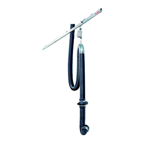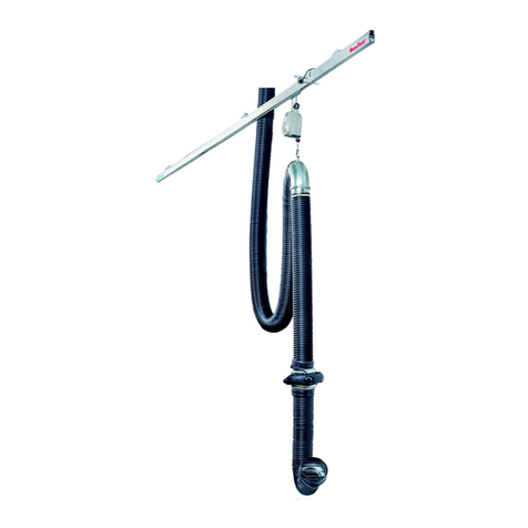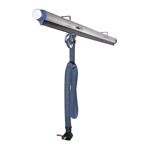
MagnaTrack HS
Declaration of Conformit
EN English
Declaration of Conformit
We, AB Ph. Nederman & Co., declare under our sole responsibility that
the Nederman product:
MagnaTrack HS (Part No. **, and stated versions of **) to which this de-
claration relates, is in conformity with all the relevant provisions of the
following directives and standards:
Directives
2006/42/EC, 2014/35/EU, 2014/30/EU
Standards
EN ISO 12100-1-2, EN 61000-6-2, EN 61000-6-4, EN 55011 class B, EN
ISO 20607:2019.
The name and signature at the end of this document is the person re-
sponsible for both the declaration of conformity and the technical file.
CS Český
Prohlášení o Shodě
My, společnost AB Ph. Nederman & Co., prohlašujeme na svou zodpo-
vědnost, že výrobek Nederman:
MagnaTrack HS (díl č. **, a uvedla, verze **), ke kterému se toto prohlá-
šení vztahuje, je v souladu se všemi příslušnými ustanoveními následu-
jících směrnic a norem:
Směrnice
2006/42/EC, 2014/35/EU, 2014/30/EU
Norm
EN ISO 12100-1-2, EN 61000-6-2, EN 61000-6-4, EN 55011 class B, EN
ISO 20607:2019.
Na konci tohoto dokumentu je jméno a podpis osoby zodpovědné za
prohlášení o shodě a soubor technické dokumentace.
DE Deutch
Konformitätserklärung
Wir, AB Ph. Nederman & Co., erklären in alleiniger Verantwortung, dass
das Nederman Produkt:
MagnaTrack HS (Art.-Nr. **, und bauartgleiche Versionen **), auf wel-
ches sich diese Erklärung bezieht, mit allen einschlägigen Bestimmun-
gen der folgenden Richtlinien und Normen übereinstimmt:
Richtlinien
2006/42/EC, 2014/35/EU, 2014/30/EU
Standards
EN ISO 12100-1-2, EN 61000-6-2, EN 61000-6-4, EN 55011 class B, EN
ISO 20607:2019.
Der Name und die Unterschrift am Ende dieses Dokuments sind die für
die Konformitätserklärung und die technischen Unterlagen verant-
wortlichen Personen.
HU Mag ar
Megfelelőségi N ilatkozat
Az AB Ph. Nederman & Co. vállalat teljes felelőssége tudatában
kijelenti, hogy a(z):
Nederman (cikkszám: **, és módosított verziói **) termék, amelyre
ez a nyilatkozat vonatkozik, megfelel az alábbi irányelveknek és
szabványoknak:
Irán elvek
2006/42/EC, 2014/35/EU, 2014/30/EU
Szabván ok
EN ISO 12100-1-2, EN 61000-6-2, EN 61000-6-4, EN 55011 class B, EN
ISO 20607:2019.
A dokumentum végén található név és aláírás a megfelelőségi
nyilatkozatért és a műszaki dokumentációért felelős személy neve és
aláírása.
PL Polski
Deklaracja Zgodności
My, AB Ph. Nederman & Co. niniejszym oświadczamy na naszą własną
odpowiedzialność, że Nederman produkt:
MagnaTrack HS [nr części ** oraz wskazane wersje **], który jest
przedmiotem niniejszej deklaracji, spełnia wszystkie odpowiednie wy-
magania wymienionych niżej dyrektyw i norm:
D rekt w
2006/42/EC, 2014/35/EU, 2014/30/EU
Norm
EN ISO 12100-1-2, EN 61000-6-2, EN 61000-6-4, EN 55011 class B, EN
ISO 20607:2019.
Na końcu niniejszego dokumentu znajdują się imię i nazwisko oraz pod-
pis osoby odpowiedzialnej za deklarację zgodności oraz dokumentację
techniczną.
SV Svenska
Överensstämmelsedeklaration
Vi, AB Ph. Nederman & Co., förklarar under vårt fulla ansvar att Neder-
man-produkten:
MagnaTrack HS (artikelnummer **, och angivna versioner av **) som
denna deklaration avser, är i överensstämmelse med alla relevanta be-
stämmelser i följande direktiv och standarder:
Direktiv
2006/42/EC, 2014/35/EU, 2014/30/EU
Standarder
EN ISO 12100-1-2, EN 61000-6-2, EN 61000-6-4, EN 55011 class B, EN
ISO 20607:2019.
Namnet och signaturen i slutet av detta dokument är den person som
ansvarar för både försäkran om överensstämmelse och den tekniska fi-
len.
**
20801964
AB Ph. Nederman & Co.
P.O. Box 602
SE-251 06 Helsingborg
Sweden
Anna Cederlund
Product Center Manager
Technical Product Management
2022-11-15
4

