Neilsen CT3950 User manual

1/2" DR MINI COMPOSITE AIR IMPACT WRENCH
CT3950
ORIGINAL INSTRUCTIONS
Cannon Tools Limited
Address: 20 Station Road, Rowley Regis, West Midlands, B65 0JU.U.K.
SAVE THESE INSTRUCTIONS AND PRECAUTIONS.
READ ALL PRECAUTONS AND INSTRUCTIONS BEFORE USE.


1
EC DECLARATION OF CONFORMITY
We CANNON TOOLS LTD
20 Station road, Rowley Regis, West Midlands,B65 0JU.U.K.
Declare that the following machine complies with the appropriate basic safety
and health requirements of the EC Directive based on its design and type, as
brought into circulation by us.
In case of alteration of the machine, not agreed upon by us, this declaration
will lose its validity.
Product description: 1/2" DR MINI COMPOSITE AIR IMPACT WRENCH
Model: CT3950
Applicable EC Directives:
EC Machinery Directive 2006/42/EC
Harmonized standards
EN ISO 12100:2010, EN ISO 11148-6:2012
20 Station Road, Rowley Regis, West Midlands, B65 0JU.U.K.
Mr. Gurcharan Tony Singh Sanghera
Managing Director
CANNON TOOLS LTD
2021-02-03

2
1. SPECIFICATION
Air pressure: 90PSI
Free speed: 10000rpm
Max. Torque: 600ft/lb
Air consumption: 3.92cfm
Air inlet:1/4"
Weight: 1.25Kg
2. SAFETY INSTRUCTIONS
WARNING –When using tools, basic precautions should always be followed,
including the following:
General
To reduce the risks of electric shock, fire, and injury to persons, read all the
instructions before using the tool.
Work Area
1.Keep the work area clean and well lighted. Cluttered benches and dark areas
increase the risks of electric shock, fire, and injury to persons.
2.Do not operate the tool in explosive atmospheres, such as in the presence of
flammable liquids, gases, or dust. The tool is able to create sparks resulting in
the ignition of the dust or fumes.
3.3. Keep bystanders, children, and visitors away while operating the tool.
Distractions are able to result in the loss of control of the tool.
Personal Safety
1.Stay alert. Watch what you are doing and use common sense when operating
the tool. Do not use the tool while tired or under the influence of drugs, alcohol,
or medication. A moment of inattention while operating the tool increases the
risk of injury to persons.
2.Dress properly. Do not wear loose clothing or jewelry. Contain long hair. Keep
hair, clothing, and gloves away from moving parts. Loose clothes, jewelry, or
long hair increases the risk of injury to persons as a result of being caught in
moving parts.
3. Avoid unintentional starting. Be sure the switch is off before connecting to the
air supply. Do not carry the tool with your finger on the switch or connect the tool
to the air supply with the switch on.
4.Remove adjusting keys and wrenches before turning the tool on. A wrench or a

3
key that is left attached to a rotating part of the tool increases the risk of personal
injury.
5.Do not overreach. Keep proper footing and balance at all times. Proper footing
and balance enables better control of the tool in unexpected situations.
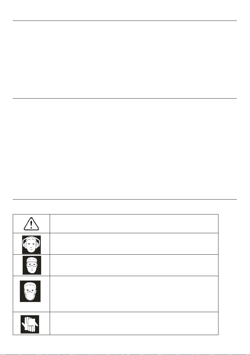
6.Use safety equipment. A dust mask, non-skid safety shoes and a hard hat
must be used for the applicable conditions. Wear heavy-duty work gloves during
use.
7.Always wear eye protection. Wear ANSI-approved safety goggles.
8.Always wear hearing protection when using the tool. Prolonged exposure to
high intensity noise is able to cause hearing loss.
Tool Use And Care
1. Use clamps or another practical way to secure and support the workpiece to a
stable platform. Holding the work by hand or against the body is unstable and is
able to lead to loss of control.
2. Do not force the tool. Use the correct tool for the application. The correct tool
will do the job better and safer at the rate for which the tool is designed.
3. Do not use the tool if the switch does not turn the tool on or off. Any tool that
cannot be controlled with the switch is dangerous and must be repaired.
4. Disconnect the tool from the air source before making any adjustments,
changing accessories, or storing the tool. Such preventive safety measures
reduce the risk of starting the tool unintentionally. Turn off and detach the air
supply, safely discharge any residual air pressure, and release the throttle
and/or turn the switch to its off position before leaving the work area.
5. Store the tool when it is idle out of reach of children and other untrained
persons. A tool is dangerous in the hands of untrained users.
6. Maintain the tool with care. Keep a cutting tool sharp and clean. A properly
maintained tool, with sharp cutting edges reduces the risk of binding and is
easier to control.
7. Check for misalignment or binding of moving parts, breakage of parts, and any
other condition that affects the tool's operation. If damaged, have the tool
serviced before using. Many accidents are caused by poorly maintained tools.
There is a risk of bursting if the tool is damaged.
8. Use only accessories that are identified by the manufacturer for the specific
tool model. Use of an accessory not intended for use with the specific tool model,
increases the risk of injury to persons.

4
3. TECHNICAL DESCRIPTION
1. Anvil 2. Trigger 3. Air inlet
4. composite body 5. Torque setting 6. Forward/Reverse selector
4. UNPACKING AND CHECKING
Carefully remove the product from the packaging and examine it for any sign of
damage that may have happened during shipping. Lay the contents out and
check them against the parts shown below. If any part is damaged or missing;
please contact the seller and do not attempt to use the product.

5
5. AIR SUPPLY
1. Ensure tool air valve (or trigger) is in “off ” position before connecting to the air
supply.
2. You will require an air pressure of 90psi, and an air flow according to
specification.
WARNING! Ensure the air supply is clean and does not exceed 90psi while
operating the tool. Too high an air pressure and unclean air will shorten the
product life due to excessive wear, and may be dangerous causing damage
and/or personal injury.
3.Drain the compressor’s air tank daily. Water in the air line will damage the tool.
4.Clean the compressor’s air inlet filter weekly.
5.Line pressure should be increased to compensate for unusually long air hoses
(over 8 metres). The minimum hose diameter should be 1/4” I.D. and fittings must
have the same inside dimensions.
6. Keep hose away from heat, oil and sharp edges. Check hose for wear, and
make certain that all connections are secure.
7.Vibration may cause failure if a quick change coupling is connected directly to
the tool.
8.To overcome this, connect a leader hose to the tool. A quick change coupling
may then be used to connect the leader hose to the air line recoil hose. See fig 1.

6
6. OPERATION
WARNING! Ensure you read, understand and apply safety instructions before
use.
1. Only use impact sockets which are specifically designed for use with an impact
wrench.
2. Connect the wrench to the air hose. Run the tool for a few seconds to check if
it is running properly.
3. Place the socket fully over the subject nut and depress the trigger to operate
the wrench.
4. You can adjust the torque by rotating the knob. Select the desired torque on
the switch located at the back or bottom part of the tool.
5. To change direction, press the “F” or “R” switch. The “F” indicates forward
and the “R” indicates Reverse.
6. DO NOT use any additional force upon the wrench in order to remove a nut.
7. DO NOT allow the wrench to free run for an extended period of time as this will
reduce bearing life.
8. After finishing the job, disconnect the air hose and put the tool away in a safe
and appropriate place to avoid any personal injury and/or damage to the tool;
9. Check if the hose is depressurized before disconnecting it from the tool.
7. MAINTENANCE
WARNING! Disconnect the wrench from the air supply before changing
accessories, servicing or performing maintenance.
Replace or repair damaged parts. Use genuine parts only. Unauthorised parts
may be dangerous and will invalidate the warranty.
1. If the air system does not have an oiler, lubricate the air wrench daily with a
few drops of #10 oil dripped into the air inlet.
2. Periodically grease the impact system in impact tools.
3. Verify periodically the condition of accessories (impact sockets and other
impact accessories) in tools.
4. Periodically check moving parts in tools.
5. Periodically check the air network tubing and hoses for any possible leaks,
condensations, and any other harmful substances that could damage tools.
6. Periodically check if the pressure regulator is set at 90 psi (6,3 bar) with the
tool turned.
7. Clean the wrench after use with a mild detergent on a moist cloth.
8. When not in use, disconnect from the air supply, store in a safe, dry, childproof
location.

7
8. TROUBLESHOOTING
Loss of power or erratic action may be due to the following:
a) Excessive drain on the air line. Moisture or restriction in the air pipe. Incorrect
size or type of hose connectors. To remedy check the air supply .
b) Grit or gum deposits in the wrench may also reduce performance. This may be
evident in the air strainer located in the area of the air inlet. Flush the wrench out
with gum solvent oil or an equal mixture of SAE No 10 oil and paraffin. Allow to
dry before use.
9. DISPOSAL
At the end of the machine's working life, or when it can no longer be repaired,
ensure that it is disposed of according to national regulations.
Contact your local authority for details of collection schemes in your area.
In all circumstances:
Do not dispose of this tool with domestic waste.
Do not incinerate.
During decommissioning of the equipment, certain hazards should be understood
and avoided:
. Only with the line pressure released shall the equipment be disassembled.
.Goggles should be worn.
10. SYMBOLS
In this manual and/or on the machine the following symbols are used:
Denotes risk of personal injury, loss of life or damage to the tool in
case of non-observance of the instructions in this manual.
Wear hearing protection.
Wear safety goggles.
Contact with or inhalation of dust coming free during use (e.g.
lead-painted surfaces, wood and metal) can endanger your health
and the health of bystanders. Always wear appropriate protective
equipment, such as a dust mask. Always use proper dust
extraction during use.
Wear gloves.

8
11. ASSEMBLY DIAGRAM AND PARTS LIST
1
2
4
5
6
9
11 12 13 14
15
22.1
22.2
22.3 22.4.1
28
29
30
22.4.3
22.4.2
10
23 24
25
26
18
21.1
21.2 21.4
21.5
21.6 21.7
21.3
3
8
16
17
31
32
19 20
27
7
33

9

10
CANNON TOOLS LTD
Add: 20 station road, Rowley Regis, west midlands,B65 0JU.U.K.
Made in China
Table of contents
Other Neilsen Power Tools manuals

Neilsen
Neilsen CT1091 User manual

Neilsen
Neilsen CT3990 User manual

Neilsen
Neilsen CT2594 Assembly instructions

Neilsen
Neilsen CT1405 User manual

Neilsen
Neilsen CT2283 User manual

Neilsen
Neilsen CT3876 User manual

Neilsen
Neilsen CT0957 User manual

Neilsen
Neilsen CT0675 User manual

Neilsen
Neilsen CT2914 User manual

Neilsen
Neilsen CT0674 User manual

Neilsen
Neilsen CT3995 User manual

Neilsen
Neilsen CT4869 User manual

Neilsen
Neilsen CT1109 User manual

Neilsen
Neilsen CT4542 User manual

Neilsen
Neilsen CT1082 User manual

Neilsen
Neilsen CT4040 User manual

Neilsen
Neilsen CT3772 User manual

Neilsen
Neilsen CT3730 Operation instructions

Neilsen
Neilsen CT4789 User manual

Neilsen
Neilsen CT4343 User manual