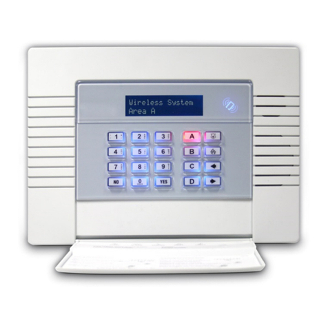
Ness D-8 User manual

MANUFACTURED BY:
Copyright © by Ness Security Products Pty Ltd
Release April 1998
To the best of our knowledge, the information in this manual is correct at the time of going to print.
Ness Security Products reserve the right to make changes to the features and specifications at any time
and without notice in the course of product development.
PA RT NO. 890-137
Sydney (Head Office)
Ness Security Products Pty Ltd
4/167 Prospect Hwy,
Seven Hills, NSW, 2147
Phone: 02 - 9624 3655
Fax 02 - 9674 2520
email: [email protected]
Brisbane
Ness Security Products Pty Ltd
36 Devlan Street
Mansfield, Qld, 4122
Phone: 07 - 3343 7744
Fax: 07 - 3849 4883
email: [email protected]
Hong Kong / Asia
Unit B, 5/f., Comfort Building,
88 Nathan Road, Tsimshatsui,
Kowloon, Hong Kong
Phone: 852 2721 8097
Fax 852 2721 7465
email: [email protected]
Melbourne
Ness Security Products Pty Ltd
24 TerraCotta Drive
Blackburn, Vic, 3130
Phone: 03 - 9878 1022
Fax: 03 9878 4257
email: [email protected]
Perth
Ness Security Products Pty Ltd
Unit 1 , 567 Newcastle Street
Perth, W.A. 6000
Phone: 08 - 9328 2511
Fax: 08 - 9227 7073
email: [email protected]
NESS SECURITY PRODUCTS PTY LTD
A.C.N. 069 984 732

NESS SECURITY PRODUCTS
D-8
CONTROL PANEL
INSTALLATION
MANUAL
A$15.00

INDEX
4
5
6
6
7
7
8
9
10
10
11
11
11
12, 13
13
14
15
16
16
17
17
18
18
18
19
20
20
20
21
21
21
22
22
22
22
23
23
25
25
26
26
27
27
27
28
PA G E
2
INTRODUCTION
Features
Package Contents
Installation Procedures
INSTALLATION
Inputs
Outputs
Wiring Diagrams
Sample Movement Detector
Sample Reed Detector
Sample Warning Detector
Keypad Wiring
Controls and Indications
Keypad and Indications
PROGRAMMING
Access to Program Mode
How to Program
PROGRAMMINGDESCRIPTIONS
User Codes (P11E- P25 E)
Setting Entry Time 1 (P26E)
Setting Entry Time 2 (P27E)
Setting Exit Time (P28E)
Setting reset Time (P29E)
Siren Time (P29E)
Vibration Sensitivity Zones (P30E-P38E)
Double Trigger Zones (P39E)
Zone Assignment
Instant Zones (P40E)
Entry Delay 1 Zones (P41E)
Handover Zones (P42E)
Entry Delay 2 Zones (P43E)
Siren Lockout Zones (P44E)
Area Operation
Assigning Area 1 Zones (P45E)
Assigning Area 2 Zones (P46E)
Assign User Codes to Area 1 (P47E-P48E)
Assign User Codes to Area 2 (P49E-P50E)
Selecting Monitor Zones (P51E)
Selecting 24 Hour Zones (P52E)
Selecting Day Zones (P53E)
Input to Output Mapping
Selecting Reset Output Zones (P54E)
Selecting Strobe Output Zones (P55E)
Selecting Keypad Sonalert Output Zones (P56E)
Selecting Siren Output Zones (P57E)

INDEX
29
29
29
27
27
28
28
28
28
29
29
29
29
30
30
31
31
32
32
33
33
34
34
35
35
35
35
36
36
36
37
38
39
40
41
41
41
43
44
44
48
54
59
PA G E
3
Selecting Zones to Auxiliary 1 Output (P58E)
Selecting Zones to Auxiliary 2 Output (P59E)
Miscellaneous Options
Entry warning Beeps (P60E 1E)
Keyswitch Operation (P60E 2E 3E)
Siren Tamper Lockout (P60E 4E)
Duress Alarm to activate “Reset” Output(P60E 5E)
Auto Excluding of Zones (P60E 6E)
Disable the Display (P60E 7E)
Area 1 Output on after Exit (P60E 8E)
Tamper Alarms to Activate selected Outputs (P61E 1E - 4E)
Panic Alarms to Activate selected Outputs (P61E 5E - 8E)
System Operating Shortcuts (P62E1E - 6E)
Auto Exclude Warning (P62E 7E)
Exit Time x 10 (P62E8E)
Monitor Mode Alarm to Selected Outputs (P63E 1E - 4E)
Day Mode Alarms to Selected Outputs (P63E 5E - 8E)
2 Second Monitor Alarm (P64E1E)
2 Second Day Alarm (P64E2E)
Pre-Alarm Monitor Warning (P64E3E)
Chirp Outputs on Keyswitch Control (P64E4E)
Dialler Options
Telephone Number 1 and 2 (P70E, P71E)
Client Account numbers (P72E, P773E)
Alarm Reporting and Restorals (P74E - P79E)
Telephone Number 3 (Test Call Number) (P80E)
Telephone Number 4 (VP/Download Number) (P81E)
Zone Restore Reporting (P82E)
Test Call Options (P83E, P84E)
Dialling Method (P85E)
Miscellaneous Reporting Options (P86E, P87E)
Open and Close Options (P88E)
Miscellaneous Dialler Options (P89E)
Up\Down Load & Remote Control Options (P90E)
Default Panel Program (P97E)
Delete Access Codes (P98E)
Installation Access Code (P99E)
Exit Programming (PE)
Testing and Troubleshooting
Voltages
SPECIFICATIONS
GETTING STARTED WITH A BASIC PROGRAM
PROGRAMMING SUMMARY
NOTES

INTRODUCTION
FE ATU RE S
The NESS D-8 is Australian Designed and Manufactured product by Ness Security Products Pty Ltd, Australia’s largest
manufacturerofqualityElectronicSecurityProducts.NessSecurityProducts PtyLtdisaQualityAccreditedCompanytoISO9001.
The Ness D-8 alarm system has been designed to provide you, the security professional, with all your most requested
features including ease of installation, ease of programming and user friendly operation in a package which is functional and
attractive. The Ness D-8 has been designed and built at an affordable price without compromising quality or features.
The High-Impact 3 mm polycarbonate housing (equivalent to 1.2 mm mild steel) not only offers strength but is aestheti-
cally pleasing and therefore easily marketable. Both the main board and the lid are removable which allows you to
easily install the system.
This manual will tell you all you need to know about installing and programming the Ness D-8. For information about
operating instructions refer to the Ness D-8 User’s Manual.
• 8 Fully programmable zones.
• Contact ID Dialler Format.
• Ultra-Modern and Impact resistant Housing.
• Ness Audible Dialler Formats.
• “Follow Me” Audible Dialler Option.
• Separate 24 Hour Tamper input.
• Single or Double Trigger Zones.
• Remote Backlit Keypads (Max 3).
•Fully programmable via the systems Keypad
- Eliminates the need for expensive
programmers or Proms.
• Inbuilt Vibration Sensor Analyser.
•All programming data is permanently stored in a
non-volatile EEprom- more secure than
battery backed-up memory.
• Windows based Up\Down load Software allows
remote programming and event status.
• True Dynamic Battery Test every time the
Panel is armed / disarmed and every hour.
•Area Partitionable (2 Areas). Any Zone can be
programmed to any area, as well as common areas.
•Comes complete with an AC plug pack and
supports a 12V DC 7 AH battery to maintain
systems security under all power
supply conditions.
• Monitor Mode (Home Mode).
• Outputs are separately fused.
• Day Mode and Door Chime feature.
•Zone inputs can be split with two end-of-line
resistors so that two detection devices
(ie reed switches) can both be monitored
to provide maximum security.
• 20 Event Memory.
•Radio Compatible with up to 8 Detection Devices
and 14 User Remote Controls.
•All inputs and Outputs are heavily protected
against lightning and high voltage supply
transients. An earth terminal is provided for
extra protection.
• 15 User Codes.
• Automatic Resettable Fuses.
• Programmable Inputs to activate
selectable Outputs.
• Designed utilising the latest SMD Technology.
• Forced Arming Feature.
• Simple to Program and Use.
4
Australian Designed and
Manufactured.

5
INSTA LLAT I ON
UN PAC KI NG
The D-8 package contains the following;
Contents Quantity
D-8 Control Panel 1
D-8 BacklitLEDKeypad 1
D-8 ZoneList 1
17 Volt A.C.Plugpack 1
12 Volt7A/H Back Up battery 1 (Optional)
2K2 Endof LineResistors 10
Housing cover screws 2
D-8 UsersManual 1
ProgrammingSummarySheet 1
Dialler Telephone Lead 1
Circuit Board Standoff 2
1. Unclip the lid by pushing in the directions of the
arrows 1 and 2 as shown below.
2. Remove the Battery from the base.
3. Mount the rear panel housing to a secure location.
4. Insert the PCB stand-offs in the Panel and then plug
the circuit board onto the stand-offs.
5. Wire to the circuit board terminal blocks, as per the
wiring instructions shown in this installation manual.
6. Replace the Battery.
7. Insert the panel tamper bracket as shown below.
8. Program Installation options (refer pages 16 - 36)
9. Perform the power-up check and carry out test
procedures. (refer Page 47, 48)
I N S TA L L AT ION PR OC ED URE S
For ease of installation it is recommended that the following procedure be followed:
Standoffs
to plug in
as shown
The location of the main panel housing should be in an area that is within the protected area of the premises. A linen
closet or cupboard are good examples as these generally located in the centre of the Premises.
Positioning of the movement detectors should be considered as the incorrect position may cause unwanted alarms.

INSTALLATION
6
INPUTS
Monitored Zones:
The Ness D-8 has 9 separate monitored inputs.
• 8 x Fully programmable Zone inputs
• 1 x 24 hour Tamper input.
Each input must be terminated with a 2K2 (2,200 ohm)
end-of-line resistor as supplied. These inputs must be
sealed with this EOL resistor regardless if they are being
used as detection inputs or not. The inputs are protected
against transient spikes through modern circuit board
design. If there are two detection loops being used for
any single zone input, then cable security may be
provided on both loops as shown in the series Zone
diagrambelow.
Note: Each pair of zones share a common terminal.
Ordinary Zone Connection
Series Zone Connection
The Tamper input is wired in an identical manner to the
Zones. It MUST be fitted with a 2K2 end-of-line resistor.
If you have 2 external siren covers, each cover can be
individually monitored by wiring as described in the
serieszonediagram.TheTampercommondoesnothave
a dedicated terminal. The Tamper common can be the 0
Volt terminal next to the Tamper terminal or any of the
other zone input common terminals.
For wiring details of Keypads, Keyswitches, Panic
Buttons and Warning devices, see the wiring diagrams
in the wiring section of this manual.
R
R = 2K2
zone
com
R
R = 1K or 1K2
zone
com R
AC Input Terminals:
These terminals are for the connection of the Ness plug-
pack. The Ness D-8 requires an AC transformer rating of
1.4 Amps @ 17 Vac minimum. (Ness Part No. Pow 215)
Battery:
These plug in terminals are for the connection of a
sealed lead-acid rechargeable 12 Volt battery, with a
minimum rating of 3.2. Charge current is limited to
350mA. The charge voltage is factory preset at 13.8 V
anddoes notneed changing. Note:A12 Volt sealedlead
acid rechargeable battery must be connected for cor-
rect panel operation. Observe correct Polarity when
connecting the battery. Ness Part Number forthe 12 volt
6.5 Ah battery is BAT-210
Earth:
For maximum protection against damage caused by
lightning strikes, connect a good earth to this terminal.
Alternatively use the Earth lead from the plug pack.
Program/Tamper Link J1:
This link is used to enter Program Mode on initial power
up. Keep the Link on these Pins except when entering
Install Program Mode on Power up.
Note: Leaving the Link off will cause a internal tamper
alarm on exit from Program Mode.

Reset:
A non-latched 12V DC voltage output controlled by the
Siren Timer, (P29E), for connecting NESS SIRENS, piezo
sirens or relays etc.
Amaximum of3 x12 VoltPiezoSirens (NessPart No.NOI
240, NOI 230) or 2 X Ness Piezo Sirens (Part No 100-172)
can be connected to this output.
Note: A maximum output of 2.0A continuous is available
in total from the Reset and Siren Outputs. (ie a Total of 4
sirendevicesbeing a combination of 12VoltPiezo Sirens
(connected to the Reset Output) AND 8 Ohm Horn
Speakers (connected to the Siren Output) can be con-
nected in total to the System.)
Area 1 Arming:
This output is an open collector (switch negative) which
can supply a maximum 100mA. It switches negative
when Area 1 is on.
Area 2 Arming:
This output is an open collector (switch negative) which
can supply 100mA. This output is turned on when Area 2
is Armed.
Aux 1:
This output is an open collector (switch negative) which
can supply 100mA. Zone alarms may be selected to trig-
ger this output by option P58E.
Aux 2:
This output is an open collector (switch negative) which
can supply 100mA. Zone alarms may be selected to trig-
ger this output by option P58E.
OUTPUTS
NOTES:
1: Output Fusing.
Power outputs on the D-8 are protected by Automatic
Resettable electronic fuses. Resetting a fuse that has
opened is automatic once the overload is removed.
2: Battery Operation.
A properly charged battery MUST be installed to ensure
the Siren, Strobe and Reset outputs operate correctly.
12 Volt Output:
A regulated 13.8 V dc output is available to power detec-
tors and ancillary equipment. This output is available
from two sets of terminals marked +12V and 0V. It also
hasaResettablefuse. Amaximum loadof 500mAmaybe
connected to these terminals.
Siren:
The Ness D-8 has an on-board siren driver, therefore
only horn speakers should to be connected to this out-
put. A maximum of 3 x 8 Ohm horn speakers (Ness Part
No. NOI 110 or 100-171 Internal Siren) can be connected
to this output. This output will reset at the end of siren
time or whenever the panel is reset, whichever comes
first. This output has an internal Resettable fuse.
Strobe:
A latched 12V DC voltage output for connecting strobes.
Thisoutputwill latch on in the event ofanalarmand stay
on until the panel is reset. A maximum of 2 x 1 Watt
Strobes(NessPartNo. NOI300)canbeconnectedtothis
Output. This output has a Resettable fuse.
7
INSTA LLAT I ON
The Ness D-8 control Panel contains the following outputs:

8
INSTA LLAT I ON
WIRING DIAGRAM
Main Control Panel:
DIALLER SOCKET
MICROPROCESSER
RECEIVER
OPEN COLLECTOR
OUTPUTS PROG
TAMP
J1
_+
AUX 1
AUX 2
ARM 1
ARM 2
12V
0V
•
•
•
•
•
•
•
•
•
••
•
TAMP
OV
+12V
Z8
C
Z7
Z6
C
Z5
Z4
C
Z3
Z2
C
Z1
OV
+12V
DAT
CLK
COM
+12V
RESET
+
STR
+
SIREN
+
AC
AC
EARTH

INS TA LLATION
WIRING DIAGRAM
Sample Wiring of Movement Detectors:
WIRING DIAGRAM
Sample Wiring of Reed Detectors:
9
Sample Wiring of Reed Switch and Nessensor Wiring to Ness Control Panel
Other Two Wires are Looped
and are for NC Tamper
E.O.L. Resistor
E.O.L. Resistor

WIRING DIAGRAM
Sample Wiring of Warning Detectors:
WIRING DIAGRAM
Wiring of D-8 Keypads:
10
INSTA LLAT I ON

11
CONTROLS AND INDICATIONS
Ness D-8 Keypad
The Ness D-8 LED Keypad consists of a Backlit 18 button
rubber keypad, 19 status lights and an internal beeper,
contained in a modern white plastic housing. The hous-
ing has a hinged front lid to protect the rubber buttons
when not in use. All the electronics are contained on a
single circuit board inside the housing.
Audible Indications
Every time a button is pressed the panel responds with a
very brief beep in acknowledgment.
The beeper is also used to indicate whether the entry
was valid or invalid. For example whenever the “Enter”
button is pressed, all the buttons pressed before it are
checked, to see whether they are valid. If they are valid,
the response will be 3 short beeps.
If they are invalid (or incorrect) the response will be 1
long beep and all previous keypresses they will be
ignored.
At other times, the beeper will indicate various warnings
such as 10 beeps for loss of Mains Power, or Low
Battery.
Installation of Keypad
• Unclip the top half of the housing by
pushing the top clips down with a
small screwdriver and pulling the
housing forward.
• Screw the base of the keypad hous-
ing to the wall using the 4 mounting
holes provided.
• Bring the 4 connecting wires to the terminal block on
the PCB that is mounted on the lid of the Keypad housing.
• Connect the wires to the screw terminals as per the
wiring diagram shown in this manual.
• Clip the top half onto the base by first engaging the
bottom clips and swinging the top closed. Push hard to
ensure the clips engage.
• Attach the Zone list label on the inside of the hinged lid.
Keypad Wiring
The D-8 Keypad connects to the D-8 Control Panel via a 4
wire connection. A Maximum of 3 keypads can be con-
nected, each wired in parallel.
The maximum cable run is 100M using 14/0.20mm cable.
If the cable is shared, then divide 100m by the number of
keypads to be connected. eg. 2 keypads on the cable
reduces the maximum run to 50M.
Dialler Telephone Line Wiring
The D-8 dialler connects to a telephone line via a Mode 3
or 5 socket. A Mode 3 or 5 connection allows the dialler
tocutoffanyexisting devices(eg. phones,faxes etc.)and
seize the telephone line so it can dial out. This method
gives priority to the D-8 dialler.
If a Mode 3 or 5 is not available on site then a Mode 3
double adaptor can be used. This allows for a dialler and
phone to be connected at the same socket. These double
adaptor plugs are available from retail outlets.
The dialler must always be connected directly to the
incoming phone line. Connecting to a PABX line may
lessen your security and or increase the problems you
may encounter. On some PABX systems the dialler may
not work at all. eg. Do not connect to an extension line of
a Telstra Commander system.
EARTH TERMINAL
For increased protection of the system electronics
against lightning strikes, connect a good Earth to the
Earth Terminal on the D-8.
INSTALLATION
___10___

INS TA LLATION
VISUAL INDICATIONS
NOT E: Radio (9) and Line (0) are used in program mode to flash out values.
LIGHT
ZONEs 1 - 8
ARMED
ARM 2
MAINS
BATTERY
MEMORY
EXCLUDE
TAMPER
PROGRAM
LINE
READY
RADIO
OFF
Zone Sealed
Day / Disarm
Day / Disarm
Normal
Normal
Normal
Normal
Normal
Zoneunsealed
PowerFault
SystemArmed
LineFault
Normal
ON
Zone Unsealed
Panel is Armed
Panel is Armed
Normal
Normal
Memory Mode Selected
PanicAlarmhasbeenactivated.
OnlydisplayedinMemory.
Exclude Mode Selected
Client Mode Selected
Whendiallermessageis
beingtransmitted.
Ready To Arm The System
Radio Key or Device Low
Batterywhendisplayedinmemory
FLASH
Zone Alarm
Monitor Mode
Mains Fail
Battery Low
AlarminMemory
Zones Excluded
Tamper Alarm
Install Program
Mode selected
When dialler failed
to communicate or
a line fault exsists.
Radio Key or
Device Low
Battery

13
PROGRAMMING
1 ) Installation Program Mode.
Program Light Flashes
In Installation Program Mode all programming options
canbechanged. This mode is used by the installer to set
up the entire system. The Program light on the Systems
Keypad flashes while in Installation Program mode
2) Client Program Mode.
Program Light On steady
InClientProgram Mode only the 15UserCodes and Entry
/ExitTime andFollowmephonenumber canbechanged.
The Program light on the Systems Keypad is on Steady
while in Client Program mode. NOTE: If no keypad but-
tons are pressed for 4 minutes, the panel will leave Client
Program Mode.
The Installer Program Mode is entered whenever pro-
gramming options are changed by the installer. It can be
accessed in two ways.
A. Access To Installation Program Mode from Initial
Power Up
Whenever Mains or Battery Power is applied for the
first time , and the PROGRAM Pins are opened (ie by
removing the Link across them) , the panel will enter
Installation Program Mode.
Thekeypadwillrespond with3Beeps and the
Program light will start to flash
You are now in Installer Program Mode. All programming
options can be programmed from this programming
mode.
Note : Replace the Link once the Ness D 8 is in Install
Program mode otherwise an internal tamper alarm will
occur when leaving program mode.
B. AccessTo InstallationProgram Mode from Operating
Mode.
The Panel must be fully disarmed (including monitor
mode) before you can access Program Mode.
You can access Installation Program Mode from normal
operating mode by pressing the following keypad
sequence.
Factory Default Master Code is 123.
The keypad will respond with 3 Beeps , all lights
willgo outandthe Programlight willcomeon steady.You
are now in CLIENT Program Mode.
ToenterInstallationprogramModefrom herepress;
(Note :The Installer codeis factory set at000000)
The keypad will respond with 3 Beeps , and the
Program light will start flashing.
You are now in Installation Program Mode. All program-
ming options can be programmed from this mode.
Program <Master Code> ..Enter..
Program <InstallerCode> ..Enter..
ACCESS TO THE INSTALLATION PROGRAM MODE
There are two programming modes within the Ness-D-8 Control Panel.

The ENTER, or Ebutton, is used to signal the end of the
button sequence just entered.
or
The programmed value is displayed by illuminating the
Zone (1-8), Line (0) and Radio (9) lights. The particular
type of indications are described for each option in the
following pages.
Installation Programming Options can be carried out in
any sequence.
14
PROGRAMMING
HOW TO PROGRAM
The PROGRAM, or Pbutton, is used to begin any
programming sequence.
or
The Numeric keys are used to enter :
a) Programming Options
b) Programmed Values.
Program P..Enter..
2 Digit Option Value
P26 ECurrentValuewillbedisplayedback 15
As we will call
it in this manual EAs we will call
it in this manual
Programming the NESS D-8 Control Panel is done via the remote keypad.
The program sequence always follows the pattern shown below.
Select your option and view the current Value Enter new value/s
EXAMPLE
Eg. To change the 'Entry Time' (which is programmed by programming option 26) from the factory default setting of
20 seconds to 15 seconds, press the following keypad sequence.
Note: - Every time you press ENTER the keypad will beep in acknowledgment.
Three quick beeps will acknowledge all is OK and accepted and one long beep . . . . indicates an invalid entry.
E
EP E

Example:Toprograma MasterCode Press;
Example: To program a Master Code to be 2468Press;
Example: To program Code 2tobe6789 Press;
Example:ToDeleteCODE2,createacodeandstartitwitha0;
To Delete ALL CODES (Including the MasterCodeand
Installation Code)Press ;
15
Ausercode isacode the clientuses to operate the panel.
The Ness -D-8 has a total of 15 user / access codes, plus
one code which is the Installer access code (as set by
Option P 99 E) and is used only for access to Installer
Program Mode. The remaining 14 codes are used for
arming/disarming etc. These codes are assigned user
numbers 1 to 15 (Options P 11 E - P 25 E)
Option P 11 E=User code1is themastercode.Themas-
ter code is the only code which can access Client
Program Mode , as well as operating the panel.
Factory Default Master Code = 123
Options P 12 E - P 25 E = User codes 2 - 15 can only
operate the panel.
Note: 1) Codes can be 3 to 6 digits in length.
2) User codes cannot start with “0”.
3) All codes must be unique to each other.
4) When entering codes you must enter it
twice for verification.
To clear an existing code you must re-program that code
with a number that starts with “0”.
P11 E E
Code Code E
P11 E E
2468 2468 E
P12 E E
6789 6789 E
P12 E E
06518 06518 E
P98 E
PROGRAMMING OPTION DESCRIPTIONS
P11 E - P25 E USER CODES (ACCESS CODES)

RADIO KEY ACCESS CODE
programming:
1. First select the code numbers to have RADIO KEY
ACCESS with Assign Access Code programming
options P 09 E, P 10 E.
2. Code 1 is barred from RADIO KEY ACCESS.
3. To learn a RADIO KEY:
i) Select the User Access Code (P12 E to P25 E).
The response is 3 beeps if it has been assigned
RADIO KEY ACCESS.
ii) Select 1E to start the panel RADIO KEY learning.
iii) Press the OFF button three times on the radio key to
be learned. A code already in use is rejected by
giving one long beep. If the response is 3 beeps the
code has been accepted.
4. To clear a RADIO KEY:
i) Select the User Access Code (P12 E to P25 E).
The response is 3 beeps if it has been assigned
RADIO KEY ACCESS.
ii) Select0E to clearthe code. Theresponse is 3beeps.
Examples:
1. To program User 2 to learn a new RADIO KEY:
P12E 1E then press the OFF button on the RADIO
KEYthreetimes.Forthis codeto operateoption P09E
must be programmed with a 2. (Access Code 2 set
for Radio Key operation
2. To delete User 10 RADIO KEY:
P20E 0E NOTE: If User code 10 needs to be a CODE
the option P10E must have zone LED 2 Off.
(Disabling code 10 from being a Radio Key)
16
Programming a Radio Key to Codes 2-15.
To Assign Access Code 2-8 to a Radio Key P09E
To Assign Access Code 9-15 to a Radio Key P10E
Radio Key codes must be assigned to Access codes the
same as Access codes being assigned to Areas.
The following options describe how to assign radio keys
to access codes.
NOTE: Byselectingaradiokey toan accessor usercode
will disable the use of a code that may be programmed
into a user code address.
User Access Codes 2 to 15 are assigned to Radio Keys
with these options.
Entering P09E displays User Codes 2 to 8 that are to be
Radio Key or code operated. Zone LED’s that are on rep-
resent access codes that are set for radio keys.
Entering P10E displays User Codes 9 to 15 that are to be
Radio Key or code operated (with code 9 status dis-
played on zone 1 LED etc ).
Now enter the User Code number to either select or
delete Radio key operation.
For P09E use the keys 2-8 to select users 2-8
For P10E use the keys 1-8 to select users 9-15
Factory Pre-set: 0 (User codes assigned to KEYPAD)
PROGRAMMING OPTION DESCRIPTIONS
PROGRAMMING RADIO KEY CODES

NOTES:
1. A RADIO DEVICE operates in parallel with the
existing hard wired zone input. Any device
connected to the zone input (both radio and hard
wired) when triggered will unseal the zone.
2. If a radio device is used the zone input must be
sealed with a 2.2K EOL Resistor.
3. If Radio devices are used vibration sensor
(P30E zone LED on) settings must be left at
factory defaults.
1. To learn a RADIO DEVICE prepare the device to
transmit (see above)
i) Select the Zone Access Code (P01 E to P08 E).
The response is 3 beeps. If a code already exists
then the appropriate zone led is displayed.
ii) Press 1E to start the panel RADIO DEVICE learning.
iii) Trigger the radio device to be learned. (See above)
A code already in use is rejected (long beep)
unless already assigned to the current zone.
The response is 3 beeps when accepted and the
appropriate zone light flashes. A steady zone light
indicates that the existing code for that zone has
not changed.
4. To clear a RADIO DEVICE:
i) Select the Zone Access Code (P01 E to P08 E).
The response is 3 beeps.
ii) Press 0E to clear any existing code.
The response is 3 beeps.
Examples:
1. Zone 4 to learn a new RADIO DEVICE:
P 04E 1E then TRIGGER the RADIO DEVICE.
2. To clear Zone 5 RADIO DEVICE: P05E 0E
Factory Pre-set: All device codes are cleared.
17
Program or Clear Zone Radio Device Code P01E-P08E
The D-8 can operate with Radio devices such as the
Ness Radio PIR and both Radio Reed switch versions.
This makes the D-8 a very flexible system. All radio
devicesare programmed with aRandomcode at the fac-
tory, it is possible though to program radio devices with
the same 16 bit code except for the Mini Reed switch
which random code cannot be changed.
The options P01E - P08E options are used to assign
RADIO DEVICES to ZONE INPUTS.
The random code used by a Radio Device must be learnt
by the panel to assigned it to a zone.
This is done by first selecting the zone using P01E (for
Zone 1 assignment) to P08E (for Zone 8 assignment ).
If a Radio device code is not programmed then the zone
LED will be OFF.
If a Radio Device code already exists then that zone LED
will be ON.
PREPARING DEVICES TO TRANSMIT
When the Radio Device is ready to transmit Press 1E to
start the code learning. To program a Radio PIR to the
D-8 connect the battery, the PIR will transmit several
messages,when thecode isaccepted 3 beepsare given
and the zone light will flash. To program a Radio Reed
switch to the D-8 have the battery connected with the
magnet is a closed position. eg. sealed with the magnet
next to the reed switch.
Move the magnet away from the reed switch and the
Reedswitch will transmit several messages, when the
code is accepted 3 beeps are given and the zone light
will flash.
PROGRAMMING OPTION DESCRIPTIONS
PROGRAMMING RADIO DEVICE CODES

The factory pre-set value = 60 Seconds
SUMMARY
To VIEW the current 'Entry 2 Time'..ENTER.. ..Enter New Value if required to be changed and Press ENTER
The factory pre-set value = 20 Seconds
SUMMARY
To VIEW the current 'Entry 1 Time'..ENTER.. Enter New Value if required and Press ENTER
Note: - Every time you press ENTER the keypad will "beep" in acknowledgment.
Three quick beeps will acknowledge all is OK and accepted and one long beep indicates an invalid entry.
18
P26 E SETTING ENTRY TIME 1
PROGRAMMING OPTION DESCRIPTIONS
P27 E SETTING ENTRY TIME 2
The 'Entry Delay Time 1' is the time the Control Panel
gives you to disarm the Panel after an 'Entry 1 Delay
Zone 'is unsecured.
The Entry Delay Time 1 can be set to a minimum of 1
second up to a maximum of 99 seconds.
To view the current Entry Time 1 enter : P 26 E
The value programmed will be displayed via the zone
(1-8) , RADIO (9) and LINE (0) lights.
To change the current value to say, 10 seconds enter 10 E
Zone 1 light will flash on for 1 second followed by the
mains light (0) to indicate the new value.
P26 ECurrent Value will be
displayed back Value E
P27 ECurrent Value will be
displayed back Value E
The 'Entry Delay Time 2' is the time the control Panel
gives you to disarm the Panel after an 'Entry 2 Delay
Zone' is unsecured.
NOTE: The Entry Delay Time 2 is set in 10 second incre-
ments instead of 1 second increments. Eg Value set at
6 = 60 Seconds
The 'Entry Delay Time 2' can be set to a minimum of 10
seconds, up to a maximum of 990 seconds (1-99)
The displaying of the current value , and setting of the
new value is done in the same way as Entry 1 Time..

The factory pre-set value = 60 Seconds SUMMARY
To VIEW the current 'Exit Time'..ENTER.. Enter New Value and Press ENTER
19
PROGRAMMING OPTION DESCRIPTIONS
The 'Exit Delay Time' is the time the control panel
gives you to secure and depart the premises after the
Panel is Armed.
The 'Exit Delay Time' can be set to a minimum of 1
second up to 99 seconds.
P28 ECurrent Value will be
displayed back Value E
P29 ECurrent Value will be
displayed back Value E
P28 E SETTING EXIT TIME
P29 E SETTING RESET TIME
The 'siren reset time' sets the Audible Alarm's operating
time. This is fixed for both the 'siren' output and the
'resetting' output.
The siren reset time can be set to a minimum of 1 minute
up to 99 minutes.
PROGRAM MODES
The Ness D-8 Control Panel has 3 modes.
1) 'Installation' Program Mode
2) 'Client' Program Mode
3) 'Remote Programming via Remote Up and Down Loading or Direct Connect.
The Programming Options P 11 E through to P 28 E can be accessed in ALL modes of programming.
(Excluding P 98 E and P 99 E)
The following programming Options can only be accessed in Installation Program Mode.
ALL Program options are programmable using the Windows Based Up\Down Load Software.
To view the current Exit Delay Time enter : P 28 E
The value programmed will be displayed via the zone
(1-8) , RADIO (9) and LINE (0) lights.
To change the current value to say, 30 seconds enter 30 E
Zone 3 light will flash on for 1 second followed by the
mains light (0) to indicate the new value.
To view the current Siren Reset Time enter : P 29 E
The value programmed will be displayed via the zone
(1-8) , Radio (9) and Line (0) lights.
To change the current value to say, 10 minutes Enter 10 E
Zone 5 light will flash on for 1 second to indicate the new value.
The factory pre-set value = 5 Minutes
Note: Check the Local Gov't By-Laws before increasing this value.
SUM MARY
To VIEW the current 'Siren Reset Time'..ENTER.. ..Enter New Value if required to be changed and Press ENTER
Other manuals for D-8
5
Table of contents
Other Ness Control Panel manuals

Ness
Ness 5000 Series User manual
Ness
Ness D24 User manual
Ness
Ness D24 Assembly instructions
Ness
Ness D16x C-Bus Enabled Assembly instructions
Ness
Ness D16 Assembly instructions
Ness
Ness pro-lx User manual
Ness
Ness D-8 Assembly instructions
Ness
Ness R16 User manual
Ness
Ness M1 Navigator Instruction Manual
Ness
Ness D-8 User manual
