Ness D24 Assembly instructions

INSTALLATION & PROGRAMMING MANUAL
D 24 CONTROL PANEL AND DIALLER
REV 1.9

COPYRIGHT NOTICE
All rights reserved. No part of this publication may be reproduced, transmitted or stored in a retrieval system in any form or by any
means, electronic, mechanical, photocopying, recording, or otherwise, without the prior written permission of Ness.
Ness reserves the right to make changes to features and specifications at any time without prior notification in the interest of ongoing
product development and improvement.
© 2012 Ness Corporation Pty Ltd ABN 28 069 984 372
NSW Ph 02 8825 9222 VIC Ph 03 9875 6400 QLD Ph 07 3399 4910 WA Ph 08 9328 2511 SA Ph 08 8152 0000
Innovative Electronic Solutions
www.ness.com.au
D24 INSTALLER MANUAL
Rev 1.9 March 2013
Document Part No: 890-253
For the product 100-660 D24 Control Panel
N55
WARNINGS & NOTICES
Ness Corporation manufacturing processes are accredited to ISO9001 quality standards and all possible care and diligence has been
applied during manufacture to ensure the reliable operation of this product. However there are various external factors that may impede
or restrict the operation of this product in accordance with the product’s specification.
These factors include, but are not limited to:
1. Erratic or reduced radio range (if radio accessories are installed). Ness radio products are sophisticated low power devices, however
the presence of in-band radio signals, high power transmissions or interference caused by electrical appliances such as Mains
Inverters, Wireless Routers, Cordless Phones, Computers, TVs and other electronic devices may reduce radio range performance.
While such occurrences are unusual, they are possible. In this case it may be necessary to either increase the physical separation
between the Ness receiver and other devices or if possible change the radio frequency or channel of the other devices.
2. Unauthorised tampering, physical damage, electrical interruptions such as mains failure, electrical spikes or lightning.
3. Solar power inverters are a known source of electrical interference. Please ensure that this product and all associated cabling is
installed at least 3 metres away from a solar power inverter and its cabling.
WARNING: Installation and maintenance to be performed only by qualified service personnel.
CAUTION: Risk of explosion if battery is replaced by an incorrect type. Dispose of used batteries in accordance with local regulations.
ADSL NOTICE: ADSL broadband data can interfere with the operation of your alarm dialler. It is recommended that a quality ADSL filter
be installed as per the filter manufacturer's guidelines in all premises with an alarm dialler installed.

CONTENTS
Features 4
Specifications 4
Installation & Power up procedures 5
D24 MAIN BOARD WIRING DIAGRAM 6
Wiring examples 7
Inputs 8
Outputs 9
D24 LCD KEYPAD 10
QUICK START PROGRAMMING 12
Program MODE levels 13
HOW TO ENTER PROGRAM MODE 13
How to EXIT Program Mode 13
Master Code (P1E) 14
User Codes 1–30 (P2E–P030E) 14
ENTRY DELAY TIMERS (P17E) 15
EXIT DELAY TIME (P18E) 15
Siren Reset Time (P28E) 15
ZONE ASSIGNMENT (P19E–P23E) 16
Zone Input response time (P252E–P258E) 17
Vibration Sensitivity (P261E–P268E) 17
Siren Lockout (P291E–P294E) 18
Excludable Alarms (P301E–P304E) 18
AREA PARTITIONING 19
Assigning Zones to Areas (P310E–P313E) 19
Assigning Monitor Zones (P321E–P322E) 19
Keypad Shortcuts (P33E) 20
Misc. System Options (P34E) 21
Map zones to output groups (P35xxE–P38xxE) 22
Map Alarms to output groups (P39xxE–P42xxE) 23
OUTPUT GROUPS & OUTPUTS, DEFINED 24
Creating Installer-defined output groups 25
Zones with no Exit Delay (P441E) 26
Test Options (P45E) 26
CLIENT CODE (P50E) 27
TELEPHONE NUMBER 1 (P51E) 27
Telephone Number 2 (P52E) 27
Telephone Number 3 - Callback (P53E) 27
REPORTING FORMAT (P54E) 28
Dialling Format (P55E) 29
Alternate Dialling (P57E) 29
Remote Access Options (P58E) 30
Required rings to Auto-Answer (P59E) 30
Open/Close Reporting Options (P60E) 30
Mapping Contact ID Channels (P61E–P64E) 31
Multiple Alarm Reporting (P65E) 32
Restorals Reporting (P66E) 32
Mains Fail Reporting Delay (P67E) 32
Zone reporting Abort Delay (P68E, P69E) 33
Test calls (P70E, P71E) 33
Easycall dialling (P72E–P74E) 34
Area Client codes (P750E–P753E) 35
Enable Options (P82E) 35
NESS RADIO INTERFACE 36
RADIO PROGRAMMING 37
Clear Radio Keys (P83E) 37
Program Radio Keys (P831E) 37
Clear Radio Devices (P84E) 37
Program Radio Devices (P841E) 37
Medical Delay (P93E) 39
General Purpose Timer (P94E, P95E) 40
INSTALLER CODE PROGRAMMING (P99E) 40
Code Retry Limit (P96E) 41
Duress Prefix (P97E) 41
FACTORY DEFAULTS (P981E–P985E) 41
OPERATING THE SYSTEM
Arming, Disarming 42
Arming, Disarming Areas 43
Monitor Mode Arming 44
Panic Alarm, Duress Alarm 44
Medical Alarm, Fire Alarm 45
VIEW MENU 46
View Memory 47
Excluding Zones 48
Test Mode 49
Test Options 49
MONITORING 50
Central Station Monitoring, Audible Monitoring 50
REMOTE OPERATION BY TELEPHONE 51
D24 OUTPUT EXPANDER 52
OPTIONS SUMMARY 54–55
INSTALLATION RECORD 56–57
CONTACT ID CODES TABLE 58

4NESS D24 CONTROL PANEL - INSTALLATION & PROGRAMMING MANUAL
The D24 alarm control panel is wholly Australian designed and manufactured
by Ness Security Products, Australia's largest manufacturer of quality electronic
security products. Ness Security Products is a Quality Accredited Company to ISO
9001.
The Ness D24 alarm control panel has been designed to provide you, the security
professional, with a 24 zone hardwired (including 8 wireless zones) control panel
featuring ease of installation, ease of programming and user friendly operation in
a package which is functional and attractive. The design and build of this product
is based on the Ness philosophy of excellence without compromise.
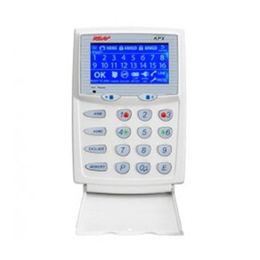
Supplied with the D24 LCD Keypad.
INTRODUCTION
D24 FEATURES
• Powerful multizone commercial
security
• 24 fully programmable zones
• 30 User Codes
• Up to 8 Radio Zones
• Contact ID Dialler Format
• Ness Audible Voice Dialler Format
• Separate 24 Hour Tamper input
• Single or Double Trigger Zones
• Remote LCD Keypads (Max 3)
• Optional 4 wire 24hr Zone Tamper
using dual EOL resistors
• Programmable Inputs to activate
selectable Outputs (Output Map-
ping)
• Inbuilt Vibration Sensor Analyser
• All programming data is perma-
nently stored in a non-volatile
EEprom memory
• True Dynamic Battery Test every
time the Panel is Armed / Dis-
armed and every hour
• Area Partitionable (3 Areas). Any
Zone can be programmed to any
area, as well as common areas
• Two separate Monitor Modes
(Home Mode)
• Outputs are separately fused with
Automatic Reset Fuses
• Day Mode feature.
• 30 Event Memory
• Supports 8 Radio Devices (Radio
PIRs, Radio Reeds etc)
• Supports 8 Radio Keys
• All inputs and outputs are heavily
protected against lightning and
high voltage supply transients. An
earth terminal is provided for extra
protection
• Comes complete with an AC plug
pack and supports a 12V 7Ah bat-
tery to maintain system security
under all power supply conditions
• Manufactured with the latest SMD
Technology
• Ultra-Modern and Impact resistant
housing
PACKING LIST 100-660 Ness D24 Control Panel
D24 SPECIFICATIONS
Construction......................... 3mm Polycarbonate (equiv. 1.2mm mild steel)
Dimensions .......................... 350W x 270H x 120D mm
Plug Pack ............................. 240V AC, output 17V AC @1.4A
Power Supply....................... 13.8V DC @ 800mA
Quiescent Current................ 80mA with 1 Keypad
Operating Voltage ................ 9.5V–14V DC
Rechargeable Battery .......... 12V 7.0 Amp/hour, lead acid
Battery Charging current ..... 350mA maximum, current limited
Dynamic Battery Test ........... Every Hour and on arming 10.75V with a 5 amp load
Fuses.................................... 2 Amp resettable / sirens & reset.
500mA resettable / 12 volt auxiliary outputs
200 mA resettable / strobe output
INPUTS
Zones ................................... 24 physical zone inputs
2 physical 24hr Tamper inputs
End of line resistor: ............. 1 x 2200 Ohm (2.2K) without Zone Tamper
2 x 4700 Ohm (4.7K) with Zone Tamper
Remote Keypad data ........... Proprietary 4 wire
Maximum Keypads .............. 3
J3 Header............................. Multi-pin connector for the Ness Radio Interface (100-200)
OUTPUTS
AUX ...................................... Open Collector output, sink current 50mA
Relay .................................... Changeover relay contacts rated 2A @ 24V
Siren A.................................. On board siren driver. Timed output.
Siren B.................................. On board siren driver. Timed output.
(Maximum 3 x 8 Ohm horn speakers over both outputs).
Strobe................................... 12V DC latching output. Maximum 2 x 1 Watt strobe lights
Reset .................................... 12V DC timed output. Maximum 3 x 12V piezo screamers
Equipment power output ..... 13.8V DC output for powering detectors and other equipment.
Maximum 500mA.
1 D24 main board
1 D24 Power Board
1 D24 housing
1 Ness D24 LCD keypad
1 17VAC plug pack
1 12V 7Ah battery (optional)
1 User manual (optional)
1 Installer manual (optional)
30 2.2K End Of Line resistors
54 4.7K End Of Line resistors
1 Lead assembly - Battery
1 Lead assembly - Internal Tamper
1 Lead assembly - Dialler
1 Zone list label

5
NESS D24 CONTROL PANEL - INSTALLATION & PROGRAMMING MANUAL
+12V
+12V
+12V
+12V
+12V
+12V
+12V
+12V
+12V
0V
0V
0V
0V
0V
0V
0V
0V
0V
105-399
D24 Power Board
0V
+12V
0V
+12V
+12V
0V
+12V
0V
+12V
0V
0V
+12V
0V
+12V
0V
+12V
+12V
0V
EARTH
17V AC
AUX
+12V
0V
NC
COM
NO
RESET
STROBE
SRN A
SRN B
SRN +
TAMP
C
KEY
C
+12V
+12V
CLK
0V
0V
DATA
KEYPAD
RESET +
STROBE +
Z1
Z5
Z9
Z13
Z17
Z21
C
C
C
C
C
C
Z2
Z6
Z10
Z14
Z18
Z22
Z3
Z7
Z11
Z15
Z19
Z23
C
C
C
C
C
C
Z4
Z8
Z12
Z16
Z20
Z24
J3
RADIO
PHONE
J1
J6
TAMPER
LISTEN
BATTERY
NESS SECURITY PRODUCTS
105-232
D24
RELAY
HEATSINK
12V 7Ah Battery
Rear Tamper Switch
Rear Tamper Switch
Document holder
Battery cradle
Lid Tamper Switch
Bolt
Bolt post
Lid
Speed nut
Circlip
Base
Lid Tamper switch
Power Board
(Screwed to bottom of base)
Housing lid bolts x2
Side cable entry
Square duct knockout
Top mounting
hole x2 (Keyhole)
Board Clip Retainers x2
(adjustable position)
Bottom mounting
hole x2 (Slotted)
Top cable entry
Square duct knockout Rear cable entry
B
B
INSTALLATION & POWER UP PROCEDURES
The control panel housing should be mounted in a location that is within a
protected zone of the premises.
Install the D24 panel as follows:
INSTALLATION
1. Insert the Rear Tamper Switch in the mounting hole in the base.
2. Screw the base to the wall using at least 4 fasteners. If mounting on an uneven surface,
make sure the rear tamper switch is correctly pushing in.
3. Insert the adjustable Board Clip Retainers in the positions as shown.
4. Insert the D24 Board. Fit the Slots “A” first, followed by slots “B”. The board should be
mounted in the second highest position.
5. Attach the supplied Speed Nuts to both Bolt Posts.
6. Fit the removable terminal strips on the two rows of pins on the D24 Board.
7. Fit the Housing Lid Tamper Switch behind the right hand bolt post.
8. Connect both tamper switches using the tamper leads supplied and plug the tamper
lead assembly into the J1 header on the D24 board.
9. Fit the backup battery in the battery cradle. The battery terminals should be at top.
10. Complete the wiring of detection devices, sirens, telephone lead, etc.
11. Power up and program the control panel.
13. Before exiting program mode, fit the housing lid. Clip the lid at the top first then swing it
down. Fasten the lid with the 2 bolts supplied. (The bolts can be made captive to the lid
using the supplied circlips).
POWERING UP
After wiring, power up as follows:
1. Make sure the J1 pins are open,
(remove the link or unseal the lid
tamper switch.) This condition
forces the panel to enter installer
program mode on power up.
2. Connect the battery, (observe
correct polarity), and connect the
plug pack.
3. The keypad will give 3 beeps
and the panel will be in Installer
Program mode, (Program icon is
flashing).
4. Replace the J1 link or seal the lid
tamper.
5. Program the panel as required.
Note 1: The panel will not exit
program mode unless User Code
1 (P1E) is programmed, all other
programming options are optional.
Note 2: If the J1 link is open (or lid
tamper unsealed) when you exit
program mode, the tamper alarm will
trigger.

6NESS D24 CONTROL PANEL - INSTALLATION & PROGRAMMING MANUAL
17V AC PLUG PACK (840-029)
Australia only (Supplied)
17V AC (Red & Black)
EARTH (White)
RELAY OUTPUT
To D24 OUTPUT EXPANDER (Optional)
TELEPHONE LEAD (Supplied)
Connect to Mode3 socket
ZONE INPUTS 1-24
D24 POWER BOARD (Supplied)
EARTH
17V AC
AUX
+12V
0V
NC
COM
NO
RESET
STROBE
SRN A
SRN B
SRN +
TAMP
C
KEY
C
+12V
+12V
CLK
0V
0V
DATA
KEYPAD
RESET +
STROBE +
Z1
Z5
Z9
Z13
Z17
Z21
C
C
C
C
C
C
Z2
Z6
Z10
Z14
Z18
Z22
Z3
Z7
Z11
Z15
Z19
Z23
C
C
C
C
C
C
N.O.
N.C.
Z4
Z8
Z12
Z16
Z20
Z24
J3
RADIO
BATTERY
NESS SECURITY PRODUCTS
105-232
D24
RELAY
HEATSINK
PHONE
J1
J6
TAMPER
CLIP THIS END FIRST when installing the board in the D24 box Multiple 12V DC outputs for detectors and other equipment
* The KEY input is the 24hr Panic input by default.
Program P400E 1E to enable KEY input as the Keyswitch input. See page 23.
To D24: 12V, 0V
CLIP THIS END LAST when installing the board in the D24 box
(THIS END CLOSEST TO THE BACKUP BATTERY)
LISTEN
STROBE LIGHT (NOI-300)
SIREN A HORN SPEAKER (NOI-110)
SIREN B HORN SPEAKER (NOI-110)
NESS 12V SIREN
TOP HAT SCREAMER
(100-172)
or (100-238)
12V DC OUTPUT - TO D24 POWER BOARD
EMERGENCY
N.C. PANIC KEYSWITCH
J3 CONNECTOR
(Optional)
NESS RADIO INTERFACE
J6 CONNECTOR
Connect 8 Ohm horn
speaker to listen to
dialler tones.
DIAGNOSTICS
BATTERY CONNECTION
Connect 12V 7Ah
backup battery
“HEARTBEAT” LED
Constantly flashes
+12V
+12V
+12V
+12V
+12V
+12V
+12V
+12V
+12V
0V
0V
0V
0V
0V
0V
0V
0V
0V
J1 LINK
&BOX TAMPER PROGRAM LINK
= Sealed, normal state
= Tamper alarm state
Power up with link off to enter
installer program mode
BOX TAMPER LEADS
(supplied)
BOX TAMPER SWITCHES
(supplied)
Box rear tamper
Box lid tamper
right hand bolt
BATTERY LEAD
(supplied)
D24 LCD KEYPAD (100-661)
(Supplied)
Maximum 3 keypads
© 2001 Ness Security Products
D24 Main Board Wiring
N.O.
2K2
N.O TAMPER SWITCH
(761-002) Colour: BLACK
Supplied with Ness siren covers

7
NESS D24 CONTROL PANEL - INSTALLATION & PROGRAMMING MANUAL
NESS D24NESS D24
NESS D24
0V
ALARM
TAMPER
N.C.
N.C.
+12V
N.C.
N.C.
0V
ALARM
TAMPER
N.C.
N.C.
+12V
N.C.
N.C.
0V
ALARM
TAMPER
N.C.
N.C.
+12V
N.C.
N.C.
NESS QUANTUM DETECTOR
(all models)
NESS QUANTUM DETECTOR
(all models)
NESS QUANTUM DETECTOR
(all models)
Any zone
1-24
Any zone
1-24
Any zone
1-24
ZoneZone
TAMP
0V
CC
C
+12V
ZoneZone
TAMP
0V
CC
C
+12V
ZoneZone
TAMP
0V
CC
C
+12V
DETECTORS-4WIRE CONNECTION, NO TAMPER
SIREN WIRING
DETECTORS-4WIRE CONNECTION WITH ZONE TAMPER
DETECTORS-6WIRE CONNECTION, WITH TAMPER
NESS D24
TAMP
C
EXTERNAL INTERNAL
TAMP
C
ALTERNATIVE 12V SIRENS:
100-172 Ness 12V Internal Siren
100-238 Top Hat 12V Piezo Screamer
RED
RED
BLACK
BLACK
N.O. TAMPER SWITCH
(761-002) Colour:BLACK
N.C. TAMPER SWITCH
(SWI920) Colour:WHITE
ALTERNATIVE TAMPERSWITCH WIRING
ForN.C. Tamper Switches
STROBE LIGHT
(NOI300)
The terminal block should
be mounted inside the
siren cover.
HORN
SPEAKER
(NOI110)
2K2
2K2
WIRING EXAMPLES
4K7
2K2
2K2
2K2
4K7
2K2
RESET
STROBE
SRN A
SRN B
SRN +
RESET +
STROBE +
ZONE TAMPER DISABLED ZONE TAMPER ENABLED
When Zone Tamper is enabled, the zones are sealed with
two 4K7 resistors which allow monitoring of both
Alarm and Tamper on each zone input over 4 wires.
Zone Tamper looks for these resistances:
When Zone Tamper is enabled, (P34E 6E = off), then
all zones must be wired as shown above, otherwise zone
alarms will be interpreted as tamper alarms.
ZONE SEALED: 2K2
ZONE ALARM: 4K7
TAMPER ALARM: OPEN CIRCUIT
NOTE:
P34E 6E is ON P34E 6E is OFF

8NESS D24 CONTROL PANEL - INSTALLATION & PROGRAMMING MANUAL
ZONE INPUTS 1–24
The Ness D24 has 24 End Of Line monitored zone inputs. Each zone input must
be terminated with a 2K2 (2200 ohm) End Of Line (EOL) resistor as supplied.
If Zone Tamper is enabled (P34E 6E off), the zones are sealed with two 4K7
resistors which allows monitoring of Alarm and Tamper states over 4 wires for
each input.
The zone input can be individually programmed for various alarm types including
Instant, Delayed, 24hr, Area, Monitor, Fire.
All inputs must be sealed with an EOL resistor even if unused.
For wiring details of Keypads, Keyswitches, Panic Buttons and Warning devices,
see the wiring diagrams in the wiring section of this manual.
TAMP - Tamper Input
The TAMP input must also be sealed with a 2K2 end of line resistor. This input is
always a 24hr input.
KEY - Keyswitch Input
This a 24hr Panic input or an optional keyswitch input for Arming/Disarming.
NOTE: By default, the KEY input is a Panic input. To use the KEY input as a
keyswitch input, program P400E 1E, (this maps the input to Output Group zero,
which disables it as a zone).
17 V AC TERMINALS
These terminals are for the connection of the Ness plug-pack. The Ness D24
requires an AC transformer rating of 1.4 Amps @ 17V AC minimum. (Ness Part
No. POW215)
EARTH
For maximum protection against damage caused by lightning strikes, connect a
good earth to this terminal. Alternatively use the Earth lead from the plug pack.
BATTERY
These terminals are for the connection of a sealed lead-acid rechargeable 12Volt
battery. Charge current is limited to 350mA. The charge voltage is factory preset
at 13.8V. A 12 Volt sealed lead acid rechargeable battery must be connected for
correct panel operation. Observe correct polarity when connecting the battery.
(Ness Part No: BAT210, 12V 7Ah battery)
J1 TAMPER - Internal Tamper Input & Program Link
The J1 link has two purposes:
1. To enter Installer Program Mode on initial power up. Power up with the J1
link OFF.
The J1 link must be ON in operating mode. (Or, if using J1 for housing tamper,
the tamper switch/es must be sealed).
2. Housing Tamper. When used with the Internal Tamper Lead (supplied), J1
serves as the 24hr tamper input for the panel’s internal tamper switch.
Replace the J1 link with the Internal Tamper Lead and tamper switches.
An EOL resistor is NOT required on this input.
When J1 is used for internal tamper, powering up with the panel’s lid open will
enter Installer Program Mode.
INPUTS
INSTALLERS’ TIP
Testing Zone Inputs - when
troubleshooting your zone wiring, the
voltages across the zone input can
help determine the wiring fault.
Correct zone voltages as follows:
WITHOUT ZONE TAMPER
(FACTORY DEFAULT)
One 2K2 resistor per input
Zone is Sealed: 4V ±0.4V
Zone is short circuit: 0V
Zone is Open circuit: 8V ±0.4V
WITH ZONE TAMPER
2 x 4K7 resistors per input
providing zone alarm and zone
tamper
Zone is Sealed: 4V ±0.4V
Zone is Unsealed: 5.4V ±0.4V
Zone is short circuit: 0V
Zone is Open circuit: 8V ±0.4V
Zone tamper is available in D24
V1.5 and later.

9
NESS D24 CONTROL PANEL - INSTALLATION & PROGRAMMING MANUAL
AUX
The AUX output is a programmable Open Collector output suitable for LEDs,
Relays, etc. This output can sink a total of 50mA.
+12V, 0V OUTPUT (x3)
A regulated 13.8 VDC output is available to power detectors and other equipment.
This output is available from three sets of terminals marked +12V and 0V. The
output is protected by an Automatic Reset fuse.
The three sets of 12V outputs can be used to power:
1. The Output Expander board (optional).
2. The D24 Power Board (supplied) and all equipment off the Power Board.
3. The D24 keypad (supplied).
A maximum load of 500mA in total can be connected to these terminals.
RELAY
The relay is a programmable output providing a set a dry changeover contacts,
(N.C. COM. N.O.) with a contact rating of 2A @ 24V.
RESET–
A 12V DC output for connecting Ness Sirens, piezo sirens or relays, etc. This
output will reset at the end of Siren Reset Time (P28E) or whenever the panel is
reset.
A maximum of 3 x 12V piezo Sirens (Ness Part No. NOI240, NOI 230, 100-238) or
2 X Ness Piezo (Part No 100-172) can be connected to this output. The output is
protected by an Automatic Reset fuse.
STROBE–
A latched 12VDC output for connecting strobe lights. This output will latch on in
the event of an alarm condition and stay on until the panel is reset.
A maximum of 2 x 1 Watt Strobes (Ness Part No. NOI300) can be connected to
this output. The output is protected by an Automatic Reset fuse.
SIREN A (SRN A–)
Siren driver output for connecting horn speakers (Ness Part No. NOI110 or
100-171 Internal Siren). The output will reset at the end of siren time (P28E) or
whenever the panel is reset, whichever comes first. This output has an internal
Resettable fuse.
SIREN B (SRN B–)
Second siren driver output. Same specifications as Siren A.
When by operating the D24 by optional Radio Key or optional Keyswitch, Siren B
will chirp to provide Arming/Disarming feedback, (if P34E 2Eis enabled).
Siren Chirps
ARMING: 1 Chirp from Siren B.
DISARM: 2 Chirps from Siren B.
J6 LISTEN LINK
Installer’s diagnostic output. Connect an 8 ohm horn speaker to listen in to dialler
tones.
KEYPAD
+12V, 0V, CLK, DATA for connecting up to 3 Ness D24 LCD keypads connected in
parallel.
The maximum recommended cable run is 100m for 1 keypad using 14/0.20 cable.
Each additional keypad will reduce the maximum cable distance accordingly.
OUTPUTS
OUTPUT FUSING
The 12V ouputs, Siren, Reset and Strobe outputs
are protected by Automatic Reset electronic
fuses. These outputs will automatically reset once
the overload is removed.
BACKUP BATTERY
A properly charged battery MUST be installed
to ensure the Siren, Strobe and Reset outputs
operate correctly.
SIREN LOAD
A maximum output of 2.0A continuous is
available from the SIREN, and RESET outputs and
200mA from the STR output.
Recommended maximum power load:
3 x Horn speakers total (SRN A and SRN B)
2 x Strobe lights (STR output)
2 x Ness Internal Sirens (100-172) (RESET
output)
Note: (This assumes no more than 500mA is
being drawn from the 12V device output).
MAXIMUM NUMBER OF HORN SPEAKERS
The D24 supports a maximum of 3 x 8 Ohm horn speakers across SRN A and SRN B.
E.g., SRN A, 2 horn speakers. SRN B, 1 horn speaker.

10 NESS D24 CONTROL PANEL - INSTALLATION & PROGRAMMING MANUAL
KEYPAD
D24 LCD KEYPAD
The Ness D24 LCD keypad provides important visual and audible indication of the system
status and is the main interface for controlling the many powerful features of the D24
system.
Information is displayed on a large LCD icon display which is backlit for easy night viewing.
NUMBER OF KEYPADS
Up to 3 LCD keypads can be connected to the D24.
CABLE LENGTH
The maximum allowable cable length is 100m (total cable length to all keypads).
Use at least 14/020 stranded cable or heavier.
The keypad/s may not work correctly if the cable runs to the keypad/s are too long or the
cable used is too thin. A 2k2 resistor added across DATA & +12 at the control panel may
improve keypad data comms in such cases. We stress the importance of heavy cable to
the keypads and you should run extra pairs to double up for power if required.
DISPLAY TEST
To display all the keypad icons press and hold the button for at least 2 seconds. All
the icons will be on whilst the button is held down.
The display test can be activated at any time either in operating mode or any program
mode.
KEYPAD INSTALLATION
1. Unclip the top half of the keypad housing by pushing the top clips
down with a small screwdriver and pulling the housing forward.
2. Screw the base of the keypad housing to the wall using the 4 mount-
ing holes provided.
3. Bring the 4 connecting wires to the terminal block on the PCB on the
rear of the keypad housing.
4. Connect the wires to the screw terminals as per the wiring diagram
shown in this manual.
5. Clip the top half onto the base by first engaging the bottom clips and
swinging the top closed. Push hard to ensure the clips engage.
6. Attach the Zone list label on the inside of the lid.
2
5
8
0
1
4
7
P
3
6
9
E
ARM
VIEW
D24
MONITOR
EXCLUDE
BACKLIT LCD
ICON DISPLAY
VIEW BUTTON
PANIC BUTTON
ARM BUTTON
MONITOR BUTTON
AREA BUTTON
EXCLUDE BUTTON
PROGRAM BUTTON ENTER BUTTON
TM
F
MONITOR
ARM ZONE TAMPER SYSTEM POWER FIRE MEMORY
AREA 1 AREA 2 AREA 3EXCLUDE PROGRAM TEST
20
12 13
21
4
10 119
191817
312
1614 15
2422 23
6578
AREA

11
NESS D24 CONTROL PANEL - INSTALLATION & PROGRAMMING MANUAL
MEMORY icon flashes to indicate
that Memory contains new events.
Memory can be viewed at any time.
E
OFF ON
Flashing
FAST
Flashing
SLOW
ZONES Zone sealed Zone unsealed Zone Alarms
present (in Armed
or Monitor Mode)
Panel is
Disarmed
Normal
Normal
Normal
Normal
Normal
Normal
Normal
Panel is
Armed
ZONE Displaying
Zone Status
TAMPER
Displaying
individual
Tamper Alarms
Tamper Alarms
present
SYSTEM
Displaying
individual
System Alarms
System Alarms
present
POWER
Displaying
individual
Power Alarms
Power Alarms
present
FIRE Fire warning
(If enabled)
Fire alarm
(If enabled)
MEMORY
Memory Mode
or View key
pressed
New alarm in
Memory
Panel is in
Monitor Mode
AREA 1 Area 1 Armed Area1Monitor
AREA 2 Area 2 Armed Area2Monitor
AREA 3 Area 3 Armed
EXCLUDE Exclude Mode Zone or other
alarm Excluded
PROGRAM User Program
Mode
TEST Siren Test
MONITOR
ARM
T
M
M
F
TAMPER ALARMS
1External Tamper
2
3
5
Control PanelTamper
Zone input Tamper
RadioInterfaceTamper
SYSTEM ALARMS
1
2
3
4
5
6
7
8
9
0
KeyswitchPanic
Diallerline fault
Keypad connectionfault
Control Panelfault
Duressalarm
Panic alarm
Medicalalarm
User Code alarm
RadioSupervision alarm
RK4Radio KeyAux button
POWERALARMS
1
2
3
4
9
0
Mains power failure
Backup Battery low
DC supply failed
Zone reference supplyfailed
RadioDevicebattery low
RadioKey battery low
1. Press
2.
3.
Memory iconturns on
Keypad icons will displaythe
most recent event as perthe
Keypad DisplayTable
Press to cancel the
Memory displayatany time
To view
alarms
TAMPER
To view
alarms
SYSTEM
To view
alarms
POWER
To view
MEMORY
4
VIEW
3
VIEW
2
VIEW
VIEW
VIEW
1-24
KEYPAD DISPLAYTable VIEW Menu Operation
Step through the Memory
display by pressing the
button. At each step,
the keypad icons display the
historyofArming, Disarming
and alarm events.
VIEW
MEMORYDISPLAY
E
E
E
E
E

12
PROGRAMMING
PROG
NESS D24 CONTROL PANEL - INSTALLATION & PROGRAMMING MANUAL
QUICK START PROGRAMMING
FROM POWER-UP
The D24 comes programmed with factory default values that should suit most
average installations.
The steps below will show you how to program the Master Code (User Code 1)
and the Client Code and telephone number for central station monitoring.
The installation must be complete - all zones wired and sealed, tampers
connected, keypad wired.
PROGRAMMING SEQUENCE:
To enter Installer Program Mode
Power up the panel with the J1 link removed, or with the box lid open if using the Tamper Lead Assembly.
(See Main Board Wiring Diagram, page 6).
The PROGRAM light will be flashing
To program the Master Code
Example Master Code is 1234.
2 21 1 1
4 4
P3 3
E E E
P1E is the option for
the Master Code
Press
Enter the new Master Code
followed by E
Enter the new Master Code again
followed by E
To program the dialler Client Code
Example Client Code is 9876.
The keypad display will flash out the new code.
To program the central station telephone number
Example telephone number is 1234 7890.
2 8
511 7
4 0
P3 9
E E
P51E is the option for
Telephone Number 1
Press
Enter the new telephone number followed by E
The keypad display will flash out the new telephone number.
To exit Installer Program Mode
The PROGRAM light will turn off.
THE PANEL IS NOW PROGRAMMED AS FOLLOWS:
Master Code:..................... 1234..........................................Example only
Dialler Client Code: ........... 9876..........................................Example only1
Telephone number:........... 1234 7890 ................................Example only1
Dialler reporting format ..... Contact ID ...............................Factory default
Zone 1 ............................... Delay / Dialler /Sirens ...........Factory default
Zone 2 ............................... Handover / Dialler /Sirens ....Factory default
Zones 3–24........................ Instant / Dialler /Sirens .........Factory default
Entry Delay Time............... 20 seconds .............................Factory default
Exit Delay Time ................. 60 seconds .............................Factory default
Siren Reset Time............... 10 minutes ..............................Factory default
1 The client code and telephone numbers are normally allocated by the central
station.

13
PROGRAMMING
PROG
NESS D24 CONTROL PANEL - INSTALLATION & PROGRAMMING MANUAL
FACTORY DEFAULT
Master Code: [blank]
Installer Code: 000000
[INSTALLER CODE]
Factory default Installer Code: 000000
[MASTER CODE]
USER PROGRAM Mode
INSTALLER PROGRAM Mode
NORMAL OPERATING Mode
Power up with J1 Link OFF
(Usually on first time installation)
PROGRAM LIGHT IS FLASHING
PROGRAM LIGHT IS ON
PROGRAM LIGHT IS OFF
PROGRAM MODE LEVELS
INSTALLER PROGRAM MODE
Installer Program Mode allows
access to ALL program options.
Note: The panel will remain in Installer
Program Mode indefinitely.
PROGRAM
PROGRAM light
is FLASHING
USER PROGRAM MODE
User Program Mode allows the
owner to program:
• All User Codes
• Entry and Exit times
Note: The panel will automatically drop
out of User Program Mode to Operating
Mode if no keypad buttons are pressed
for 1 minute.
PROGRAM
PROGRAM light
is ON
HOW TO ENTER PROGRAM MODE
FROM POWER UP
1. Power-up with the J1 link OFF.
The J1 link must be ON in operating mode. (Or, if using J1 for housing tamper,
the tamper switch/es must be sealed).
USING THE KEYPAD
The panel must be Disarmed.
1. Press
[MASTER CODE]
The keypad will respond with 3 beeps
This is User Program Mode (PROGRAM light is ON).
2. Then press
[INSTALLER CODE]
The keypad will respond with 3 beeps
This is Installer Program Mode (PROGRAM light is FLASHING).
HOW TO EXIT PROGRAM MODE
1. Press then
This is Operating Mode (PROGRAM light is OFF).
KEY SEQUENCE IN PROGRAM MODE
3 beeps
Selects a program
option (address)
The current value
is displayed
The keypad lights or
icons will display the
current value
Enter new
data
3 beeps
2-4 digit Option No. Enter
new value
THE PANEL WILL NOT EXIT
PROGRAM MODE UNLESS
USER CODE 1 (P1E) IS
PROGRAMMED.

14
PROGRAMMING
PROG
NESS D24 CONTROL PANEL - INSTALLATION & PROGRAMMING MANUAL
USER CODES 1–30
User codes are the P.I.N. codes used to operate various panel functions,
especially Arming and Disarming. There are 30 User Codes and each can be 3 to
6 digits long.
User Code 1 is always a MASTER CODE.
User Codes 2 to 30 can be programmed as one of the types: ORDINARY,
ADMINISTRATOR, AREA or MASTER.
When programming codes, the User Code type is indicated by the icons:
ARM
If User Code 1 was used to enter Program Mode, the digits of any existing codes
will be displayed when programming a User Code.
ORDINARY CODE & ADMINISTRATOR CODE
An Ordinary Code is for systems configured without Areas. Allows full access to
the panel except for entry to Program Mode. (When the panel is partitioned this
code is called the Administrator Code).
An Administrator Code is able to Arm and Disarm all Areas of a Partitioned system,
but it is not allowed entry to Program Mode.
To Program an Ordinary Code or Admin Code: [OPTION] [CODE] [CODE]
The
ARM
icons will be ON.
AREA CODE
An Area Code is a code which only has access to the Area assigned to it.
To Program: [OPTION] [AREA No.] [CODE] [CODE]
One of the icons or or will be ON, depending on [Area No.] entered.
MASTER CODE
A Master Code is able to Arm and Disarm all Areas of a Partitioned system and
is allowed entry to Program Mode. User Code 1 is always a Master Code, but all
other codes can be programmed as Master Codes if needed.
To Program: [OPTION] 0 [CODE] [CODE]
The
ARM
icons will be FLASHING.
EXAMPLES:
Program User Code 1, the permanent Master Code, to be 1234: P1E 1234E 1234E
Program User Code 2 to be 789 and an Ordinary Code: P2E 789E 789E
Program User Code 3 to be 5678 and an Area 1 Code: P3E 1E 5678E 5678E
Program User Code 4 to be 222 and an Area 2 Code: P4E 2E 222E 222E
Program User Code 5 to be 8990 and an Area 3 Code: P5E 3E 8990E 8990E
P1E – P030E
PROGRAM MODE LEVEL:
User, Installer, Remote by PC
FACTORY DEFAULT:
[blank]
TO PROGRAM:
P[Option No] E [new code] E [new code] E
NOTES:
• User Codes can be 3 to 6 digits in length.
• User codes cannot start with ‘0’.
• All codes must be unique to each other.
• The panel is supplied with NO user codes
programmed.
• To delete a code, re-program the code as 000.
e.g, To Delete User Code 2: P2E 000E 000E
• To clear all codes, enter P982E in Installer
Program mode. See Page 41.
• Codes are rejected if already used. Some
codes that are similar to existing codes may
also be rejected.
• Open/Close reports are identified by user
number when the control panel is central
station monitored.
RELATED OPTIONS:
Program Installer Code, page 40
USER CODE DEFAULT
User Code 1 (Master Code)
User Code 2
User Code 3
User Code 4
User Code 5
User Code 6
User Code 7
User Code 8
User Code 9
User Code 10
User Code 11
User Code 12
User Code 13
User Code 14
User Code 15
User Code 16
User Code 17
User Code 18
User Code 19
User Code 20
User Code 21
User Code 22
User Code 23
User Code 24
User Code 25
User Code 26
User Code 27
User Code 28
User Code 29
User Code 30
OPTION No
P1E
P2E
P3E
P4E
P5E
P6E
P7E
P8E
P9E
P10E
P11E
P12E
P13E
P14E
P15E
P16E
P017E
P018E
P019E
P020E
P021E
P022E
P023E
P024E
P025E
P026E
P027E
P028E
P029E
P030E
PROGRAMMING FEEDBACK
When programming user codes, the existing code and then the new code is ‘read back’ by flashing the
numeric keypad icons 0–9.
1. Press: P [Option No] E the existing code is displayed by the keypad.
2. Enter the new code (3 to 6 digits): [New code] E
3. Enter the new code again: [New code] E, the new code will be displayed.
NOTE: After step 1, the new code can be entered immediately without waiting for the display to finish the ‘read back’.

15
PROGRAMMING
PROG
NESS D24 CONTROL PANEL - INSTALLATION & PROGRAMMING MANUAL
ENTRY DELAY TIMERS
The Entry Delay Time is the time given to Disarm the panel after an Entry Delay
zone is unsecured.
P17E
This is the Global Entry Delay Time. Any value programmed at this option also
changes all other Entry Delay Timers.
P170E
This is the Entry Delay timer for zones assigned to more than one area. Any value
programmed at this option also changes P17E. (P171E, P172E, P173E are not
affected).
P171E, P172E, P173E
Area 1, 2 and 3 Entry Delay times can be individually programmed with different
values.
P17E – P173E
PROGRAM MODE LEVEL:
User, Installer, Remote by PC
FACTORY DEFAULT:
see table
TO PROGRAM:
P [Option No] E [New time] E
EXAMPLE:
To program 30 sec Global Entry Delay: P17E 30E
NOTES:
• All timers are programmable from 1–99
seconds
EXIT DELAY TIME
The Exit Delay Time is the time given to vacate the premises after the panel is
Armed. All zones except 24 hour zones are disabled during the Exit Delay Time.
P18E
This is the Global Exit Delay Time. Any value programmed at this option also
changes all other Exit Delay Timers. If different exit delays are required for each
Area use P181E–P183E.
P181E, P182E, P183E
Area 1, 2 and 3 Exit Delay Times can be individually programmed with different
values.
P18E – P183E
PROGRAM MODE LEVEL:
User, Installer, Remote by PC
FACTORY DEFAULT:
see table
TO PROGRAM:
P [Option No] E [New time] E
EXAMPLE:
To program 55 sec Global Exit Delay:
P18E 55E
NOTES:
• All timers are programmable from 1–99
seconds
OPTION No DESCRIPTION DEFAULT
P17E
P170E
P171E
P172E
P173E
P18E
P181E
P182E
P183E
Entry Delay Time
Entry Delay Time for zones in multiple areas
Entry Delay Time for AREA 1
Entry Delay Time for AREA 2
Entry Delay Time for AREA 3
Exit Delay Time
Exit Delay Time for AREA 1
Exit Delay Time for AREA 2
Exit Delay Time for AREA 3
20 Seconds
Seconds
Seconds
Seconds
Seconds
Seconds
Seconds
Seconds
20
20
20
20
60
60
60
60
Seconds
P28E Siren Reset Time
10 Minutes
SIREN RESET TIME
The Siren Reset Time sets the duration of the Siren and Reset outputs.
Programmable from 1 – 99 minutes
P28E
PROGRAM MODE LEVEL:
Installer, Remote by PC
FACTORY DEFAULT:
10 Minutes
TO PROGRAM:
P [Option No] E [New time] E
EXAMPLE:
To program 5 minute Siren Time:
P28E 5E
PROGRAMMING FEEDBACK
When programming timers, the existing
time and then the new time is ‘read back’ by
flashing the numeric keypad icons 0–9.
1. Press: P [Option No] E the existing time
is displayed by the keypad.
2. Enter the new time: [New time] E, the
new time will be displayed.
NOTE: The new time can be entered
immediately without waiting for the display
to finish the ‘read back’.

16
PROGRAMMING
PROG
NESS D24 CONTROL PANEL - INSTALLATION & PROGRAMMING MANUAL
ZONE ASSIGNMENT
Each zone can be assigned with attributes which determine how the zone will be
used.
P19E
Security Delay can be assigned to zones already assigned to more than one Area,
(Common Area Zones).When a Common Area Zone is assigned as a Security
Delay Zone, the zone is Armed as soon as any Area it belongs to is Armed.
(Unlike normal Common Area Zones, which are Armed only when all assigned
Areas are Armed).
P20E
Instant zones do not have Entry Delay.
P21E
Entry Delay Zones operate only in the Armed state. These zones will activate the
Entry Delay Timer (P17E) when they are triggered. If the panel is not Disarmed
before the expiry of the Entry Delay Timer, the programmed alarm outputs will be
activated.
P22E
Handover zones are delayed only if entry is made through an Entry Delay zone
first. If a Handover zone is triggered first, the zone behaves as an instant zone.
Normally, the “point of entry” zone should be Delay zone, with any other zones in
the entry path programmed as Handover zones.
P23E
Secondary Delay Zones have an entry delay time eqivalent to the Exit Delay Time
(P18E).
P271E
Single Trigger is the default for all zones. The zone alarms on each single trigger.
P272E
Zones programmed to Double Trigger will recognise an alarm condition if:
• The Double Trigger zone has been triggered twice within a 4 minute period.
• If any 2 Double Trigger zones, each trigger once.
• A Double Trigger zone is left unsealed for longer than 15 seconds.
Double Trigger is suitable for zones with devices such as PIRs which self reset.
P19E – P272E
PROGRAM MODE LEVEL:
Installer, Remote by PC
FACTORY DEFAULT:
see table
TO PROGRAM:
P[Option No] E [Zone No] E
Turns the option ON for each zone selected.
NOTES:
• Selecting a zone attribute will turn off any other
attribute within the same Selection Group.
RELATED OPTIONS:
P441E Zones With No Exit Delay, page 26
SELECTION
GROUP
Only one
option is
selectable
per zone
SELECTION
GROUP
OPTION No DESCRIPTION 12345678 9101112131415161718192021222324
Zones
P19E Security delay zones
P20E Instant zones
P21E Entry Delay zones
P22E Handover zones
P23E
Secondary delay zones
P271E Single trigger zones
P272E Double trigger zones
ON
ON
ON
ONONON
ON
ON
ON
ON
ON
ON
ON
ON
ON
ON
ON
ON
ON
ON
ON
ON
ON
ON
ON
ON
ON
ON
ON
ON
ON
ON
ON
ON
ON
ON
ON
ON
ON
ON
ON
ON
ON
ON
ON
ON
ON
ON
Factory default settings shown

17
PROGRAMMING
PROG
NESS D24 CONTROL PANEL - INSTALLATION & PROGRAMMING MANUAL
ZONE INPUT RESPONSE TIME
P251E–P258E
The input response time can be adjusted for each zone. The factory default is
440ms. This option does NOT normally need to be adjusted.
This option is NOT related to Vibration Sensitivity.
Zones are allocated to one sensitivity level at any one time. Turning a zone ON in
a sensitivity level, turns the zone OFF in any other sensitivity level.
P251E – P258E
PROGRAM MODE LEVEL:
Installer, Remote by PC
FACTORY DEFAULT:
P254E: All zones, Normal Sensitivity
TO PROGRAM:
P[Option No] E[Zone No] E
Turns the option ON for each zone selected.
SELECTION
GROUP
Only one
option is
selectable
per zone
OPTION No TIME (milliseconds) 12345678 9101112131415161718192021222324
Zones
P251E 100
P252E 200
P253E 400
P254E 440 (Normal)
P255E 480
P256E 520
P257E 560
P258E 600
ON ON ON ON ON ON ON ON ON ON ON ON ON ON ON ON ON ON ON ON ON ON ON ON
Factory default settings shown
SELECTION
GROUP
Only one
option is
selectable
per zone
OPTION No PULSES within 600ms 12345678 9101112131415161718192021222324
Zones
P261E 1
P262E 2
P263E 3
P264E 5
P265E 10
P266E 15
P267E 20
P268E 25
HIGHEST SENSITIVITY
LOWEST SENSITIVITY
Factory default settings shown
VIBRATION SENSITIVITY
P261E–P268E
Each zone has individually adjustable sensitivity for connection of Nessensor
Vibration Sensors. Vibration Sensitivity counts pulses at 20ms intervals for a time
window of 600ms.
There are 8 levels of vibration sensitivity. P261E is the most sensitive setting.
P268E is the least sensitive setting. (Avoid using highest and lowest sensitivity
– they are provided as a guide to the upper and lower limits).
P261E – P268E
PROGRAM MODE LEVEL:
Installer, Remote by PC
FACTORY DEFAULT:
no zones selected
TO PROGRAM:
P[26x] E[Zone No] E
Turns the option ON for each zone selected.
NOTES:
• Zones are allocated to one sensitivity level
at any one time. Turning a zone ON in a
sensitivity level, turns the zone OFF in any
other sensitivity level.
USING NESSENSORS.
Nessensors are sensitive to high frequencies and
insensitive to low frequencies. Therefore it is not
necessary to apply much force to the protected
structure, rather a very rapid succession of
blows.
The sensitivity has been correctly adjusted when
a single blow applied with a soft object (e.g. by
hand) does not cause an alarm whereas a rapid
series of blows (using a metal object such as a
screwdriver blade) will cause an alarm.
M
H
LL
RED
YELLOW
N/C Vibration
contacts
N/C Tamper
loop
BLUE
GREEN
36mm
51mm
20mm
16.5mm
350mm cable
2 x
at 27mm spacing
3mm holes
ADJUSTMENT
In addition to zone sensitivity
adjustment, the overall
sensitivity of the Nesssensor
can be adjusted by rotating the
body of the Nesssensor within
its bracket.
The bracket must always be
mounted horizontally and the
arrow must point up for the
required setting.
Ness NESSENSOR Vibration sensor
Part No. VIB100
For efficient operation, Nessensors must be attached
to fixtures using screws, not adhesive tape or silicone.

18
PROGRAMMING
PROG
NESS D24 CONTROL PANEL - INSTALLATION & PROGRAMMING MANUAL
SIREN LOCKOUT
Select the zones or alarms which will have Siren Lockout.
Siren Lockout zones/alarms will sound the Siren output once only during any
Armed period but further alarms will trigger the Reset and Strobe output, (if
programmed).
P291E Siren Lockout Zones
P292E Siren Lockout Tamper Alarms
P293E Siren Lockout System Alarms
P294E Siren Lockout Power Alarms
P29xE
PROGRAM MODE LEVEL:
Installer, Remote by PC
FACTORY DEFAULT:
see table
TO PROGRAM:
P[29x] E[Zone No] E
Toggles the option ON and OFF.
P302E Excludable
P303E Excludable
P304E Excludable
P292E Lockout
P293E Lockout
P294E Lockout
TAMPER ALARMS
External Tamper 1E
1E
1E
Control Panel Tamper 2E
2E
2E
Zone input Tamper 3E
3E
3E
Radio Interface Tamper 5E
4E
4E
5E
9E
6E
0E
7E
8E
9E
0E
POWER ALARMS
Mains power failure
Backup Battery low
DC supply failed
Zone reference supply failed
Radio Device battery low
Radio Key battery low
SYSTEM ALARMS
Keyswitch Panic
Dialler line fault
Keypad connection fault
Control Panel fault
Duress alarm
Panic alarm
Medical alarm
User Code alarm
Radio Supervision Alarm
RK4 Radio Key AUX button
ON ON
ON
ON
ON ON
ON
ON
ON ON
ON
ON
ON ON
ON
ON
ON
ON
ON
ON
ON
ON
ON
ON
Factory default settings shown
EXCLUDABLE ALARMS
Select the zones or alarms which can be Excluded.
P301E Excludable Zones
P302E Excludable Tamper Alarms
P303E Excludable System Alarms
P304E Excludable Power Alarms
P30xE
PROGRAM MODE LEVEL:
Installer, Remote by PC
FACTORY DEFAULT:
see table
TO PROGRAM:
P[30x] E[Alarm No] E
Toggles the option ON and OFF.
OPTION No DESCRIPTION 123456789101112131415161718192021222
32
4
Zones
P291E
P301E
Siren Lockout ZONES
Excludable ZONES
ON
ON
ON
ON
ON
ON
ON
ON
ON
ON
ON
ON
ON
ON
ON
ON
ON
ON
ON
ON
ON
ON
ON
ON
ON
ON
ON
ON
ON
ON
ON
ON
ON
ON
ON
ON
ON
ON
ON
ON
ON
ON
ON
ON
ON
ON
ON
ON

19
PROGRAMMING
PROG
NESS D24 CONTROL PANEL - INSTALLATION & PROGRAMMING MANUAL
AREA PARTITIONING
DEFINITION
Area Partitioning allows the 24 zones to be split into 4 partitions; Areas 1, 2, 3 and
Administrator (Admin) area.
By default, all zones are assigned to the Admin area. When there are no zones
assigned to areas, a full Arm or Disarm turns the Admin area on and off.
COMMON AREA ZONES
Zones assigned to more than one area are armed only when all the assigned
areas are armed.
Common Area Zones will automatically Arm only when all the assigned areas are
Armed. Common Area Zones will automatically Disarm when any of the assigned
areas Disarms.
OPERATION
Operation depends on the type of user code being used.
Area operation only applies to zones when they are in the armed state. This
means that Day, 24hr and Monitor zones are independent of the area operations.
Note: Area partitioning is in addition and separate to Monitor Mode.
ASSIGNING ZONES TO AREAS
P310E Assign zones to Administrator area
When a zone is assigned to the Admin area it is automatically removed from all
other areas.
* P310E is used only to add zones to the Admin area. When a zone is assigned to
any other area it is automatically removed from the Admin area.
P311E Assign or remove zones from Area 1
P312E Assign or remove zones from Area 2
P313E Assign or remove zones from Area 3
P310E – P313E
PROGRAM MODE LEVEL:
Installer, Remote by PC
FACTORY DEFAULT:
All zones assigned to Admin area.
TO PROGRAM:
P[31x] E[Zone No] E*
Toggles the option ON and OFF.
NOTES:
• If no Area operation is required, assign all
zones to the Admin area (P310E).
OPTION No DESCRIPTION 123456789101112131415161718192021222
32
4
Zones
P310E
P311E
P312E
P313E
P321E
P322E
Assign zones to ADMIN AREA
Assign zones to AREA 1
Assign zones to AREA 2
Assign zones to AREA 3
Assign zones to MONITOR 1
Assign zones to MONITOR 2
ON ON ON ON ON ON ON ON ON ON ON ON ON ON ON ON ON ON ON ON ON ON ONON
Factory default settings shown
ASSIGNING MONITOR ZONES
Monitor mode allows partial arming of the system - eg., for night-time perimeter
protection.
If also using Area Partitioning, assign Area 1 zones to Monitor 1 and Area 2 zones
to Monitor 2.
P321E Assign zones to Monitor 1
P322E Assign zones to Monitor 2
P321E – P322E
PROGRAM MODE LEVEL:
Installer, Remote by PC
FACTORY DEFAULT:
No monitor zones.
TO PROGRAM:
P[32x] E[Zone No] E
Toggles the option ON and OFF.
NOTES:

20
PROGRAMMING
PROG
NESS D24 CONTROL PANEL - INSTALLATION & PROGRAMMING MANUAL
ON
ON
OPTION No DESCRIPTION DEFAULT
P33E KEYPAD SHORTCUTS
Two button keypad operation1E
Shortcut ARMING2E
Shortcut EXCLUDE3E
KEYPAD SHORTCUTS
These options will determine the keystrokes required to Arm, Monitor, Exclude,
Panic, View.
P33E 1E Two button keypad operation
If this option is on, the ENTER button is also required for the above operations.
E.g., Press ARM ENTER to Arm, MONITOR ENTER to Monitor, etc. Otherwise the
keypad operation is single button.
P33E 2E Shortcut ARMING
If this option is on, a user code is not required to Arm.
P33E 3E Shortcut EXCLUDE
If this option is on, a user code is not required to Exclude.
P33E, 1E–3E
PROGRAM MODE LEVEL:
Installer, Remote by PC
FACTORY DEFAULT:
Shortcut Arming & shortcut Exclude ON.
TO PROGRAM:
P33 E[Option] E
Toggles the option ON and OFF.
NOTES:
P33E SUMMARY
1E OFF, 2E ON, 3E ON
Single button Arm/Monitor/Exclude
1E ON, 2E OFF, 3E ON
Arm/Monitor via code
1E ON, 2E ON, 3E OFF
Arm/Monitor/Exclude via code
or 2 button (Arm/Monitor/Exclude + E)
Other manuals for D24
1
Table of contents
Other Ness Control Panel manuals
Ness
Ness D16 Assembly instructions
Ness
Ness D16 Assembly instructions
Ness
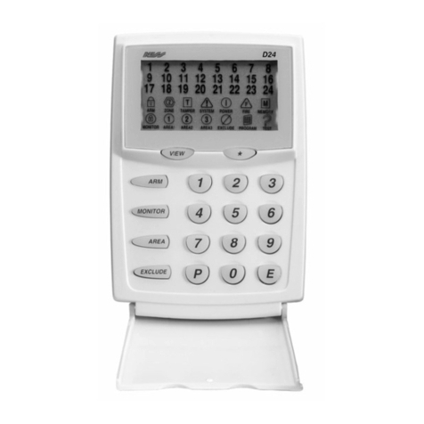
Ness D24 User manual
Ness
Ness D-8 User manual
Ness
Ness D-8 User manual
Ness
Ness D16x C-Bus Enabled Assembly instructions
Ness
Ness D8X User manual

Ness
Ness D8X User manual
Ness
Ness D8xD User guide
Ness
Ness M1 Navigator Instruction Manual


