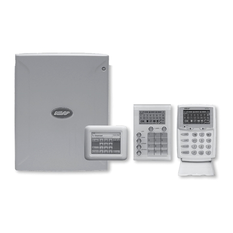
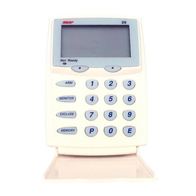
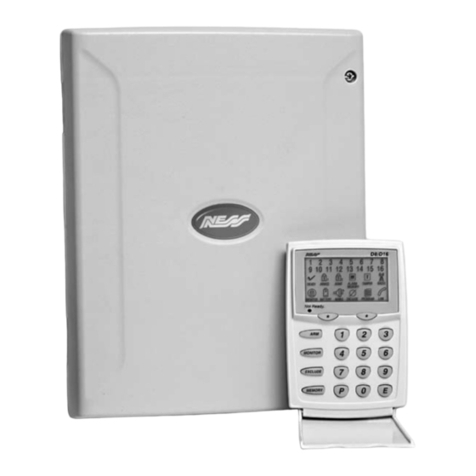
Ness D-8 User manual

OP ERAT I ON S U M M A RY
To arm <optional code>
To disarm or Reset Alarm <code>
To monitor zones <optional code>
To exit monitor mode <code>
To exclude zones <optional code>
then <zone> <zone> etc.
To exit exclude mode
To include zones <optional code>
then <zone> <zone> etc.
To exit include mode
Panic alarm
To Reset Alarm <code>
To view memory <optional code>
PA RT N O . 8 9 0- 1 36
Arm
M onitor
.. Enter ..
.. Enter ..
.. Enter ..
.. Enter .. .. Enter ..
.. Enter .. .. Enter ..
.. Enter ..
.. Enter ..
.. Enter ..
Panic
.. Exclude ..
.. Enter ..
.. Exclude ..
.. Enter ..M emory
.. Enter ..
.. Enter ..
.. Enter ..
24
To view
next press M emory

NESS SECURITY PRODUCTS
D-8
CON T R OL P AN E L
OWNE R S MANU AL

NE SS SE CURI T Y P RODUCTS P TY LTD
A.C.N. 069 984 732
Sydney
( H E A D O F F I C E )
4/167 Prospec t Highw ay
Seven Hills 2147
N.S.W Australia
Sydney
02 9624 3655
Brisbane
07 3343 7744
M elbourne
03 9878 1022
Perth
08 9328 2511
Hong Kong
852 272 18097
Copyright© by Ness Security Products
APRIL 1998 V1.0
To the best of our knowledge, the information contained in this manual
is correct at the time of going to print. Ness Security Products reserve
the right to make changes to the features and specifications at any time and
w ithout notice in the course of product development.
M A N U FA CT U RED B Y:
Quality
Endorsed
Company
ISO9001
Lic No QEC2074
NSW Head Office

3
PA GE CO N T EN T S
I N T RO D U C T I ON
Terminology
CON T ROLS A N D I N DI CATI ON S
Keypad
Buttons
Audible Indications
Visual Indications
Radio Key & Device Control / Indications
(Optional)
O P ERAT I ON
Operating Rules
Area Operation
Arming Your Alarm System
Disarming Your Alarm System
M onitor M ode
Emergency Functions-Panic
Alarms
Resetting an Alarm
Excluding Zones
Including Zones
Alarm M emory
P RO G R A M M I N G
To Enter Program M ode
To Exit Program M ode
How To Program Access Codes
How To Program Entry and Exit Times
To Program Entry 1 Timer (option 26)
To Program Entry 2 Timer (option 27)
To Program Exit Timer (option 28)
To Program Follow M e Telephone Number
(option 00)
Programming Summary
Troubleshooting
Installation Record
Operation Summary
4
5
6
6
6
6
7
8
8
8
9
10
11
12
13
13
14
15
16
17
17
17
18
19
20
20
20
21
21
22
23
24

4
Thank you for purchasing a Ness D-8 control panel, proudly designed and built in Australia, by
Ness Security. The D-8 control panel is very pow erful but easy to use, utilising the latest in
microprocessor technology. Please take time to read this manual so that you understand the
benefits of the control panel.
I N T R OD U C T I O N
External
Siren
Internal
Siren
Strobe
Siren Cover
(w ith Tamper)
Rechargeable
Battery
Front Door Zone 1
Window s Zone 2
Side Door Zone 3
Hallw ay Zone 4
Zone 5 to Zone 7
Garage Zone 8
Plug Pack
( E X A M P LE O F A T Y P I C A L S Y S T EM )
DETECTORS &
SW ITCHES
Optional
Keysw itch
Optional
Radio Key
w ith Panic
(14 M ax)
240V
in
17V
out
D-8 Keypad
onal Radio Devices
ll zones

5
The micro computer based 8 zone control panel forms
the heart of your security system and connects to all
other equipment. Each zone of the panel can be
connected to one or more detection devices to protect
an area such as the front door, hallw ay, w indow s, etc.
Detection devices may be connected to the D-8
control system through the use of either directly
c onnecting devices with cabling or w ith optional
Radio (w ireless) devic es.
Detection devices called Passive Infra-Red Detectors
(or P.I.R’s for short) c an detect the movement of an
intruder by sensing their body heat. P.I.R’s are used to
cover various critical areas of your premises w here
an intruder may enter or trespass. Another detection
device used is called a Reed Sw itch. Reed Sw itc hes
are attac hed to w indow s and doors to detect if a
w indow or door has been opened. A Reed Sw itch is
made up of tw o parts. A magnet w hich is normally
attac hed to the moving part of a w indow or door and a
Reed sw itch w hich is used to detect the presence or
absence of the magnet.
The panel is said to be armed w hen it is set to detect
an intruder. At other times it is disarmed.
Normally a zone is considered secured. Activation of
a detec tion device w ill cause the zone to be
unsecured and may cause an alarm.
Detectors such as fire detectors and panic buttons
must be able to generate an alarm at all times
egardless of the panel setting. A zone w ith this
assignment is called a 24hour zone.
Some detection devices may only be required to
generate an alarm or w arning only w hen the panel is
disarmed. A zone w ith this assignment is called a
day zone.
Before leaving the premises you must arm the panel to
enable it to detect intruders and generate an alarm.
After arming, the panel w ill ignore detectors for the
exit delay time to enable you to d epart w ithout
triggering an alarm.
Arming the system may be done through the keypad or
w ith the use of optional radio keys for Arming from
outside the premises.
When you enter the premises the panel w ill ignore
selected zones for the entry delay time and w ill not
alarm unless you fail to disarm the panel during this
allow ed time.
Disarming the system may be done through the
keypad or w ith the use of optional radio keys for
Disarming from outside the premises.
M onitor mode allow s selected zones to be armed
w hile leaving others disarmed if you w ish to protect a
number of zones w hile you are at home.
If you w ish to split your alarm system into tw o areas
w ith access limited to each area by code numbers
then area operation is used. Optional radio keys may
be used to control area operation.
The control panel housing and the c overs over exter-
nal sirens are protected by tamper sw itc hes to detec t
someone attempting to disable the security system.
Activation of these switches will cause an instant
tamper alarm.
If a detector becomes faulty, you can exclude the
associated zone so that it is totally ignored and cannot
generate an alarm. Including the zone w ill enable it to
generate an alarm again.
The control panel is fitted w ith a rechargeable stand-
by battery to ensure your security system continues to
operate if the mains pow er is interrupted. This battery
is checked every hour and w henever you arm/disarm
the panel.
Whenever an alarm occurs, it may be silenced by
entering an access code or by optional radio keys,
otherw ise it w ill reset at the end of alarm reset time.
All alarms are stored in memory and may be view ed at
any time by entering memory mode.
T ER M I N O LO GY

6
CO N T RO LS A N D I N D I CAT I O N S
K E Y PA D
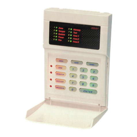
The D-8 keypad consists of 18 buttons, 19
indicators and 1 internal beeper.
B U T T O N S
The 10 numeric buttons are used for entering
access codes and in program mode to enter
option selections and values.
The Enter button is used at the end of every
sequence to store the selected data.
A U D I B LE I N D I C AT I O N S
Every time a button is pressed on the keypad,
it responds w ith a brief beep in acknow l-
edgment.
The beeper is also used to indicate w hether
the entry was valid or invalid. For example,
w henever enter is pressed, all the buttons
pressed before it are checked to see w hether
they are valid. If they are valid, the response
w ill be 3 short beeps.
If they are invalid (or incor rect) the response
w ill be 1 long beep and they will be ignored.
-
At other times, the beeper w ill sound w arnings
such as 10 beeps for a low battery or mains fail.
-10-
The beeper may have been programmed to
sound continuously if an alarm has occurred.
------
. . EN T E R. .

7
V I S U A L I N D I CAT I O N S
Each of the 19 indicator lights have three possible states. These are:-
N O T E : Radio (9) and Line (0) are used in program mode to flash out values.
LIGHT
ZONEs 1 - 8
ARM ED
ARM 2
M AINS
BATTERY
M EM ORY
EXCLUDE
TAM PER
PROGRAM
LINE
READY
RADIO
OFF
Zone Sealed
Day / Disar m
Day / Disar m
Normal
Normal
Normal
Normal
Normal
Zone unsealed
Power Fault
SystemArmed
LineFault
Normal
ON
Zone Unsealed
Panel is Armed
Panel is Armed
Normal
Normal
M emory M ode Selected
Panic Alarmhas beenactivated.
Only displayed in M emory.
Exclude M ode Selected
Client M ode Selected
When dialler message is
being transmitted.
Ready To Arm The System
Radio Key or Device Low
Battery when displayed in memory
FLASH
Zone Alar m
M onitor M ode
M ains Fail
Battery Low
Alarm in Memory
Zones Excluded
Tamper Alar m
Install Program
M ode selected
When dialler failed
to communic ate or
a line fault exsists.
Radio Key or
Device Low
Battery

8
O P ERAT I ON
This section describes the operation of a
typical control panel installation. Keep in
mind that your installation may vary depend-
ing on the selected options and equipment.
The operating instructions w hich follow w ill
endeavour to cover the most common options.
Consult your installation company if you
require further information.
All control panel operations are controlled
by the D8 keypad except if an optional key
sw itch or radio control equipment is
installed.
OP ERAT I N G RU L ES
Generally, the panel w ill be Disarmed. Armed
or M onitor modes provide different levels of
security for your premises for w hen you are
home or aw ay. Three other temporary modes
Program, M emory and Exclude, allow you to
perform various operations. The panel w ill
automatically exit from these temporar y
modes if you do not press any buttons on the
keypad in a 4 minute period.
If you make a mistake w hile entering any
codes, press the enter button and start
again.
When you are required to enter your access
code, you are given five opportunities to
enter it cor rectly. After the fifth invalid
attempt the alarm is activated (requiring the
correct code to silence the alarm). This pre-
vents anyone trying to guess your code by
entering random numbers.
A REA OP E RAT I O N
The D8 control panel allow s for the 8 zones
to be split into tw o groups know n as area 1
and area 2.The tw o areas can be assigned
access codes so that a user may have
access either of the areas or both areas.
This allow s for people to have access to one
part of your premises w hile the other part
remains armed.
This is know n as area operation. Arming and
disarming is carried out as normal. You may
have keypads installed in each area and set
up by your installer so that the armed light
indicates the armed state for that area only.
N O T E: All zones w hich are active in the
armed mode alw ays exist in one or both
areas, eg. even if you do not require your
8 zones to be split, all 8 zones w ill be
programmed to operate in area 1.

The control panel must be armed prior to
vacating the premises in order to detect
intruders. Ensure that the panel is not in
Program, M emory or Exclude modes.
N O T E: If the panel is already in alarm,
you must first silence the alarm before you
can arm.
These are three methods of arming the panel:
1. Normally the panel is armed by pressing
Arm then Enter.
2. Your installer may have programmed the
panel to require the entry of a code to arm
the panel.
3. Using an optional radio key to arm the
panel by pressing the ‘on’ button.
To Arm your system w ith the optional radio keys follow the sequence below ;
1. Check that the ready light is on by closing all doors and w indow s.
2. Press the ‘ON’ button on your radio key. The keypad w ill beep three times and the
armed light w ill come on.
3. Leave the premises w ithin the exit delay time.
4. The keypad w ill beep three times at the end of exit time.
Note: If Arming from outside it is possible to have the outside siren pop and the strobe
to flash for tw o seconds to indicate that the system has been armed.
9
A R M I N G Y O U R A LA R M S Y S T E M
If something is w rong when Arming the
control panel, the normal 3 beeps w ill be
eplaced by other w arnings.
• M ains pow er is turned off
• Control Panel battery is low
• A long beep indicates an invalid entry
or an alarm is outstanding and needs
to be reset by entering your access
code first.
SIREN WARNING:At the end of the exit time,
all zones should be secured. If any are unse-
cured, the siren w ill sound for 2 seconds as a
w arning to indicate that those zones have
been automatically excluded. For maximum
security, you should return, DISARM , check the
premises and then ARM again. Continual
w arnings could mean that a detector is faulty
and may have to be manually excluded.
If the auto-exclude option is disabled, the siren
w ill sound for the duration of reset time if a
zone is unsec ured at the end of exit time.
1. CHECK that the ready light is on by closing all w indow s and doors.
2. P RES S
or code
3. The arm light should be ON .
4. L E AV E the premises w ithin your exit delay time.
5. At the end of the exit delay time, three beeps w ill sound.
Arm
Arm
..Enter..
..Enter..
Ready

10
D I SA RM I N G Y O U R A LA RM S Y S TEM
Upon entering the protected premises through
a delay zone, the keypad responds with regular
beeps as a reminder to disarm. You then have
your programmed entry delay time to disarm
the panel by Entering one of your access
codes. If the panel is not disarmed by the end
of the entry delay time, an alarm w ill occur.
You may enter your code to silence the alarm.
By using the optional radio keys you may
disarm your system from within your premises
or from outside your entrance door. There is
also the option to pop the outside siren three
times and to flash the strobe light for tw o
seconds as an indication that you have
disarmed your system. Note: There are
advantages using radio keys to disarm your
system. They allow you to have an instant
alarm or a ver y short entry delay before the
alarm. An intruder is more likely to flee if the
sirens are triggered as soon as a door or
window is opened.
If one of your codes is, say, 7676 then to
disarm press…
7 6 7 6 e n t e r
If you make a mistake in entering your code,
then you must press enter and start again.
Five incor rec t entries w ill c ause an alarm.
1. EN TER the protected premises via a delay zone.
2. LI S TEN for the beeps coming from the keypad.
3. P RES S . . . code
4. The armed light should now be extinguished..
The entry beeps can be disabled as a function of the installation options.
If the external strobe light (if fitted) is flashing before you disarm then this means that an alarm
occurred since you last armed the panel. Flashing indicators on the keypad also indicate the
location of the alarm before you disarm. Once you have disarmed, you may view the alarm
memory to check the location of the alarm. (See alarm memory page 16)
..Enter..
Press the ‘OFF’ button on any programmed Radio key. The outside
siren w ill pop three times and the strobe light flash for tw o seconds
if selected. The Armed light on the keypad w ill also go out.
When disarming w ith the optional radio keys, the system may be
disarmed from outside the premises or after you have entered the premises.
Disarming w ith Radio Keys

11
M O N I T O R M O D E
M onitor mode allow s you to arm selected
zones w hile others are ignored. Typically,
perimeter zones (doors and w indow s) can be
monitored w hile you are at home.
To select M onitor mode,
A) press <M onitor> <Enter>
or
<M onitor> <code> <Enter>
The control panel w ill respond w ith 3 beeps
and the armed indicator w ill flash to indicate
that you are in M onitor mode.
M onitor mode cannot be selected w hile in
Program, M emory or Exclude modes.
To exit from M onitor mode: press,
<code> < Enter> to disarm.
N o t e :
If an alarm occurs w hile in M onitor mode,
entering <code> <Enter> w ill silence the
alarm. This will also change the mode of
operation of your panel, so remember to
enter monitor mode again if necessar y.
1. To EN T E R monitor mode, press…
2. If an A LA RM occurs, the respective zone light will flash.
3. To S I LEN C E the alarm
and to exit monitor, press… code
M onitor ..Enter..
..Enter..
Entering M onitor M ode w ith Radio Keys
1. Press the ‘OFF’ button tw ice w ithin five seconds on any programmed Radio Key. The
Armed light w ill flash and the key pad w ill beep three times to indicate monitor mode.
2. If an alarm occurs the respective zone light w ill flash.
3. To silence the alarm and exit monitor mode press the ‘OFF’ button once. The armed
light w ill go out and the keypad w ill beep three times.

12
EM ERGEN CY FU N CT I O N S - PA N I C
For personal protection, the keypad contains
an instant panic feature. Panic can be used
to…
•Scare aw ay intruders inside
or outside your premises.
•Summon help from friends
or neighbours.
•Test the operation of the siren.
The panic function may have been
programmed to be either:
1 / Audible - activates siren or buzzers
or
2 / Silent - activate a warning in another
part of your building.
To activate the panic alarm, press
<Panic> <Enter> or press both panic
buttons simultaneously
(dependant on whic h programming option selected)
To silence the siren, press
<code> <Enter>
Panic cannot be used w hile the panel is in
Program, M emory or Exclude mode.
N O T E: Your installer may have installed a
separate panic button. To activate the panic
alarm simply press the button.
1. PANIC!
2. Press…
3. The siren w ill SOUND
4. Press… code
The siren w ill S T O P
Panic ..Enter..
..Enter..
To activate the Panic Alarm using the optional Radio Keys
1. Press and hold the panic button (It must be held for more than 2.5 seconds)
2. The siren w ill sound.
3. To silence the siren Press the ‘OFF’ button on the radio key or enter a
valid code at the remote keypad. The siren w ill stop.

13
A LA RM S
D U RES S
R ES E T T I N G A N A L A R M
Alarms may be caused by one of the follow ing:
•A zone has been activated w hile armed
•A tamper has been activated
•A Panic button has been activated
All of these may cause your sirens and strobe
to operate. Various visual indications relevant
to the alarm w ill be retained in the memory. If
this occurs, disarm your Control Panel w hic h
w ill reset the alarm. The cause of the alarm
can be identified by entering the Alarm
M emory M ode as described on page 16.
M emory plus * indicates C A U S E O F A L A R M
Your panel can be reset and the alarm
silenced by entering your CODE follow ed by
the ENTER button.
If you arrive at your premises and find the
strobe light flashing (if installed), reset the
panel as above. To check the cause of the
alarm, you can view the alarms in memory
by entering memory mode.
To Reset an alarm, press … code
or
Press the ‘OFF’ button on a Radio key (optional)
..Enter..
e.g. To disarm normally you w ould press
6 8 6 1 <Enter>. To disarm under a duress
situation you w ould press 9 6 8 6 1 <Enter>
The system w ill disarm normally and send a
silent duress alarm to the central station.
A Duress Alarm is w hen another person is
forcing you to disarm your alarm sysyem. If
this occurs you can generate a silent duress
alarm simply by prefixing your exsisting
code w ith either a 5, 6, 8 or 9 digit w hen
disarming.

14
EX CL U D I N G Z O N E S
If a detector becomes faulty and cannot be
secured w hen arming the panel, then its
zone may be excluded so that it does not
generate alarms.
To enter Exclude mode press,
<Exclude> <Enter>
or
<Exclude> <code> <Enter>
All the lights w ill be turned off and then the
Zone Excluded indicator w ill show a steady
light. You may now exclude zones.
To exclude, say, zones 4 and 8, press the
buttons…
<Exclude> <Enter>
4 <Enter> 8 <Enter>
Zone lights 4 and 8 will turn on.
<Enter> to Exit Exclude M ode
N O T E: Excluding zones can only be done
w hen the panel is disarmed.
1. To exclude zones…
2. Press…
or
code
the Exclude light should be On
3. ENTER the zone/s to be EXCLUDED Zone No.
4. To EXIT press ENTER
If you make a mistake, enter the zone number again to remove it from your selection.
Zones which you exclude w ill be identified by the relevant zone indicator show ing a steady
light in the exclude mode.
N O T E: Your Control Panel may be programmed to automatically exclude faulty zones
w henever you Arm. The Exclude light w ill flash as a w arning or memory of the auto-exclusion.
If Auto - Exclude is selected the outside Siren w ill sound for 2 seconds indicating a zone has
Auto Excluded.
Exclude ..Enter..
..Enter..Exclude
..Enter..
..Enter..

15
I N CLU D I N G ZO N ES
Zones w hich have been exc luded, may be
ncluded w hile you are in the Disarm modes.
All Exc luded Zones ar e automatically includ-
ed w hen the panel is Disarmed. Thus if a
detector is still faulty it must be Excluded
again.
The exclude light w ill flash to w arn you of
excluded zones.
To view Exclude Zones for Inclusion press,
<Exclude> <Enter>
or
<Exclude> <code> <Enter>
To include, say, zones 4 and 8, press
<Exclude><Enter>
<4> <Enter> <8> <Enter>
Zone lights 4 and 8 w ill turn off.
<Enter> to Exit Exclude M ode
1. To include zones, press …
or
code
the Exclude light should be On
2. ENTER the zone/s to be INCLUDED Zone No.
3. To EXITpress ENTER
Exclude ..Enter..
..Enter..Exclude
..Enter..
..Enter..

16
A LA RM M EM O RY
The D-8 Control Panel contains an compre-
hensive Alarm M emor y. The D-8 w ill remem-
ber Arms, low batter y, mains fail and alarms.
The memory is constantly upgraded and the
ast 20 events are alw ays available for view ing.
To view the memory display, enter…
<M emory> <Enter> w ill show the last event,
pressing <M emory> again w ill show the
previous event etc
or
<M emory> <code> <Enter> w ill show the
last event, pressing <M emory> again w ill
show the previous event etc
This M emory display can only be selected
w hile the panel is in the Disarmed state.
N O T E: Entry to Program M ode w ill clear
the events from Alarm M emory.
M emory ..Enter..
1. To view memory , press…
2. OBSERVE lights .
The last event will be displayed. Press the M emory button to view the previous
event, Press the M emory button again to view the previous event etc until all
events have been displayed.
The lights are used as follow s:
Light Alarm
Zone light Zone alarm
Arm light Panel armed
Tamper light Tamper alarm (siren cover, panel etc.)
Exclude Panic alarm
Battery light Low battery
M ains light M ains failure
Radio, Battery, Zone Radio Device Low Batter y
Radio, Battery, Arm Radio Key Low Battery
You can access the Alarm M emory as often as required
w hile the Panel remains Disarmed.
You can exit M emory M ode at any time by pressing the Enter Key.

17
T O EN T ER P R OGR A M M OD E
P RO G R A M M I N G
T O E X I T P RO GRA M M OD E
The D-8 Control Panel allow s you to reprogram all 15 available access codes, the
2 entry times, your exit time and the follow me telephone number.
You may need to reprogram an access code because you no longer w ish a user to have
access to your system or because you w ant to give somebody temporary access to
your system, or you may have simply forgotten your code.
You may also need to reprogram the entry or exit times of your entry/exit zones if you
find them too long or too short. You may also change the ‘Follow M e’ telephone
number in Client program mode.
For all other programming changes, talk to your installer.
Access code number 1 is called your master
code. Program mode can only be accessed
using your master code. To enter program
mode, press…
<Program> <master code> < Enter>
The program light w ill turn on and all other
lights will turn off to indicate successful
access to program mode.
N OT E : Access to Program mode can only
be done from the disarmed state.
To enter Program mode, press…
Program light ON
Press, <Program> <Enter>
The program light w ill turn off and normal operating lights (mains and battery w ill turn on).
To exit Program mode, press…
Program
Program
..Enter..
..Enter..
M aster Code
Important: The control panel w ill automatically exit the Program mode if no keys are pressed
w ithin a four minute period.
Important: The control panel w ill automatically exit the Program mode if no keys are pressed
w ithin a four minute period.

18
H OW T O P RO GRA M A C CES S CO D ES
To program any of the 15 access codes, you
must know a few rules first.
R EM EM B ER :-
• All codes can be 3, 4, 5 or 6 digits long.
• Codes cannot begin with a 0 (see below).
• A code can be cancelled by
reprogramming it again w ith a
code of 000.
• Codes must be unique and cannot be a
subset of each other.
Eg. If a Code-2 is 1234,code-3 234
(not allow ed) code-6 1334 (allow ed).
• Code-1 is the master code and M UST be
programmed. All other codes are optional
• Ask your installer about programming the
optional Radio keys into your system if
required.
When you enter your new code number the
D-8 requires that you input the code tw ice to
confirm a cor rect code.
Each user access code has a 2 digit program
option number to ensure the panel can
identify w hich code number you w ant to
program.
The options for each code are:-
Code Option Code Option
1 11 9 19
2 12 10 20
3 13 11 21
4 14 12 22
5 15 13 23
6 16 14 24
7 17 15 25
8 18
To Program Codes, press…
2 digit option no.
Code no code no.
A long beep indicates an error has been made-start again.
Example to program code 1 to be 2468.
Prog 11 enter 2468 Enter 2468 Enter
Program ..Enter..
..Enter.. ..Enter..

19
H O W T O P R OG RA M E N T R Y A N D E X I T T I M ES
Your D-8 Control Panel w ill have zone(s)
w hich are called Entry/Exit zones. These are
the zone(s) through w hich you enter and exit
your premises. To allow you to do so w ithout
causing a false alarm, there is an Exit Time
w hich the Control Panel gives you to depart
your premises after you Arm the Panel.
There are 2 separate entry times which the
Control Panel gives you to Disarm the Panel
w hen you have entered the premises before
an alarm occurs.
Your installer may have programmed differ -
ent zones w ith a long entry time and a short
entry time zone. (A long and short entry time
is useful if you enter by a garage or a front
door).
TO PROGRAM YOU M UST KNOW A FEW RULES:
Exit time can be programmed from 1 to 99
seconds in 1 second increments.
Entry 1 time can be programmed from 1 to
99 seconds in 1 second increments.
Entry 2 time can be programmed from 10 to
990 seconds in 10 second increments,
Each one of the timers has a 2 digit program
option number.
The current timer value is displayed by the
D-8 w hen you select a timer option. The
value is displayed by flashing out the value
on the numeric zone lights 1 to 8, 9= Radio
and 0= Line at 1 second intervals.
When you change the timer value the new
value is displayed as above. The option
numbers are as follow s;
Programming alw ays follow s this sequence;
Entry 1 timer = Option 26
Entry 2 timer = Option 27
Exit time = Option 28
To view a timer, press…
2 digit option Value
Displayed
To change a timer , press…
New Value New Value
Displayed
Program ..Enter..
..Enter..
Other manuals for D-8
5
Table of contents
Other Ness Control Panel manuals

Ness
Ness D8X Assembly instructions
Ness
Ness R8 User manual
Ness
Ness D16 Assembly instructions
Ness
Ness D-8 User manual
Ness
Ness D8X Assembly instructions
Ness
Ness D16 Assembly instructions
Ness
Ness M1 Navigator Instruction Manual
Ness
Ness D24 Assembly instructions
Ness
Ness D24 User manual

Ness
Ness D8XCEL User guide
Popular Control Panel manuals by other brands
NAPCO
NAPCO MA3000 Basic operating instructions
See Water
See Water WS Series Installation and operator's manual

SJE Rhombus
SJE Rhombus 123 Installation Instructions and Operation/Troubleshooting Manual
Simplex
Simplex 4100-S1 Programming guide
Miranda
Miranda iMC-Panel-300 Operator's guide
Ikegami
Ikegami MCP-300 Operation manual
