NI REM-11152 User manual

-~
ARTISAN
®
~I
TECHNOLOGY
GROUP
Your definitive source
for
quality
pre-owned
equipment.
Artisan Technology
Group
Full-service,
independent
repair
center
with
experienced
engineers
and
technicians
on staff.
We
buy
your
excess,
underutilized,
and
idle
equipment
along
with
credit
for
buybacks
and
trade-ins
.
Custom
engineering
so
your
equipment
works
exactly as
you
specify.
•
Critical
and
expedited
services
•
Leasing
/
Rentals/
Demos
• In
stock/
Ready-to-ship
•
!TAR-certified
secure
asset
solutions
Expert
team
ITrust
guarantee
I
100%
satisfaction
All
tr
ademarks,
br
a
nd
names, a
nd
br
a
nd
s a
pp
earing here
in
are
th
e property of
th
e
ir
r
es
pecti
ve
ow
ner
s.
Visit our website - Click HERE
GETTING STARTED GUIDE
NI REM-11152
Digital Input Module for Remote I/O
This document explains how to connect to the REM-11152.
Note The guidelines in this document are specific to the REM-11152. The other
components in the system might not meet the same safety ratings. Refer to the
documentation for each component in the system to determine the safety and EMC
ratings for the entire system.
Caution Do not operate the REM-11152 in a manner not specified in this
document. Product misuse can result in a hazard. You can compromise the safety
protection built into the product if the product is damaged in any way. If the product
is damaged, return it to NI for repair.

Isolation Withstand Voltages
Test section Test voltage
5 V communications power (logic), 24 V supply (I/O) 500 VAC, 50 Hz, 1 min.
5 V supply (logic)/functional earth ground 500 VAC, 50 Hz, 1 min.
24 V supply (I/O)/functional earth ground 500 VAC, 50 Hz, 1 min.
Electromagnetic Compatibility Guidelines
This product was tested and complies with the regulatory requirements and limits for
electromagnetic compatibility (EMC) stated in the product specifications. These requirements
and limits provide reasonable protection against harmful interference when the product is
operated in the intended operational electromagnetic environment.
This product is intended for use in industrial locations. However, harmful interference may
occur in some installations, when the product is connected to a peripheral device or test object,
or if the product is used in residential or commercial areas. To minimize interference with
radio and television reception and prevent unacceptable performance degradation, install and
use this product in strict accordance with the instructions in the product documentation.
Furthermore, any changes or modifications to the product not expressly approved by National
Instruments could void your authority to operate it under your local regulatory rules.
Preparing the Environment
Ensure that the environment in which you are using the REM-11152 meets the following
specifications.
Operating temperature -25 °C to 60 °C
Operating humidity 5% RH to 95% RH, noncondensing
Pollution Degree 2
Maximum altitude 3,000 m
Indoor use only.
Note Refer to the device datasheet on ni.com/manuals for complete specifications.
2| ni.com | REM-11152 Getting Started Guide

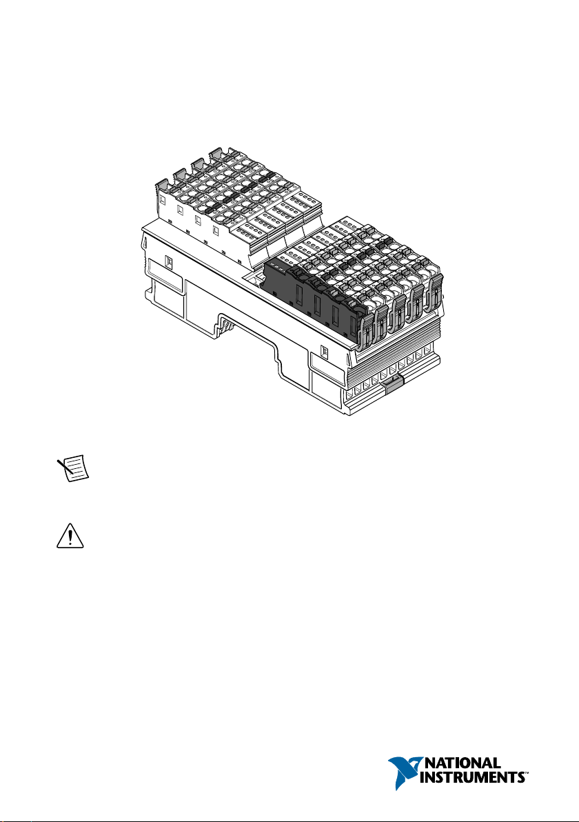
Verifying the Kit Contents
Verify that the following items are included in the REM-11152 kit.
Figure 1. REM-11152 Kit Contents
12 3 4
1. NI REM-11152
2. Bus connector
3. Supply voltage connector
4. Spring-terminal block (x8)
Unpacking the Kit
Caution To prevent electrostatic discharge (ESD) from damaging the device,
ground yourself using a grounding strap or by holding a grounded object, such as
your computer chassis.
1. Touch the antistatic package to a metal part of the computer chassis.
2. Remove the device from the package and inspect the device for loose components or any
other sign of damage.
Caution Never touch the exposed pins of connectors.
Note Do not install a device if it appears damaged in any way.
3. Unpack any other items and documentation from the kit.
Store the device in the antistatic package when the device is not in use.
REM-11152 Getting Started Guide | © National Instruments | 3
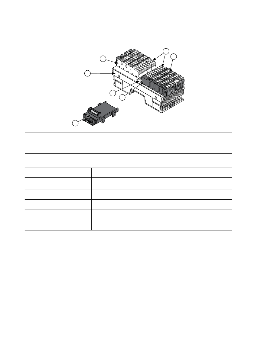
Installing the REM-11152
Figure 2. Structure of the REM-11152
1
5
3
4
6
5
2
1. Bus connector
2. REM-11152
3. Module function label
4. Supply voltage connector
5. Spring-terminal block
6. LED indicators
Table 1. Module Function Labels
Label Color Module Function
Blue Digital input
Red Digital output
Green Analog input, thermocouple
Yellow Analog output
White Bus coupler, power module
Installing Bus Connectors
What to Use
• Bus connector
• DIN rail
What to Do
Complete the following steps to install bus connectors on the DIN rail.
4| ni.com | REM-11152 Getting Started Guide
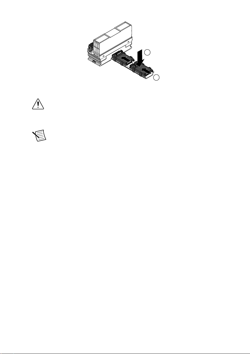
1
2
1. Insert the bus connector for the REM-11152 into the DIN rail.
Caution Verify that you are using the correct bus connector for the module
width.
2. Slide the bus connector along the DIN rail until it connects to the preceding bus
connector.
Note A bus connector will not attach to a preceding bus connector with a
mounted module. Remove the preceding module before installing additional
bus connectors.
3. Repeat Steps 2 and 3 for additional bus connectors.
Installing the Module
What to Use
• REM-11152
• Mounted bus connector
What to Do
Complete the following steps to install the REM-11152 on the DIN rail.
REM-11152 Getting Started Guide | © National Instruments | 5
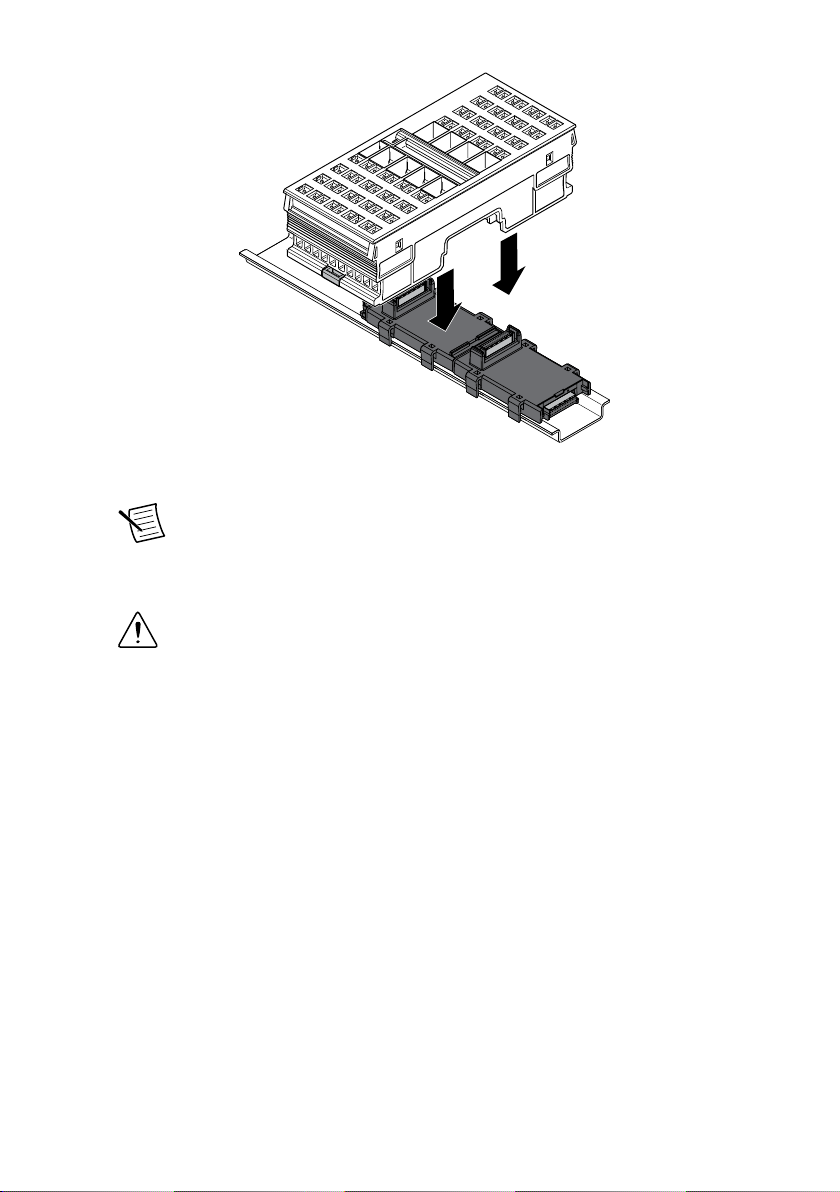
1. Align the REM-11152 over the appropriate bus connector.
Note Verify that the bus connector socket aligns with the socket on the
underside of the module.
2. Press the REM-11152 directly onto the bus connector and DIN rail until it clicks into
place.
Caution Tilting the module when mounting it on the DIN rail will damage the
contacts.
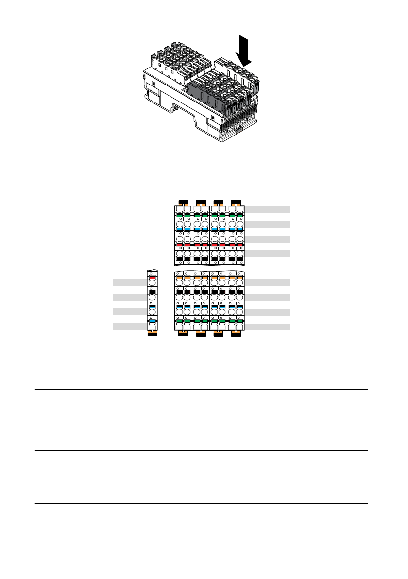
Installing Spring-Terminal Blocks
What to Use
• REM-11152
• Spring-terminal block
What to Do
Align the spring-terminal block over the REM-11152 and press until it clicks into place.
6| ni.com | REM-11152 Getting Started Guide
REM-11152 Pinout
71
61
51
41
70
60
50
40
73
63
53
43
72
62
52
42
75
65
55
45
74
64
54
44
77
67
57
47
76
66
56
46
00
10
20
30
01
11
21
31
04
14
24
34
05
15
25
35
06
16
26
36
07
17
27
37
02
12
22
32
03
13
23
33
DI0 to DI7
24 VDC
GND
FE
DI8 to DI15
24 VDC
GND
FE
24 VDC
24 VDC
GND
GND
a1
a2
b2
b1
Table 2. REM-11152 Signal Descriptions
Signal Color Description
a1, a2 Red 24 VDC (UI) Supply to digital input modules (internally
jumpered)
b1, b2 Blue GND Reference potential of the supply voltage
(internally jumpered)
00 to 07 Orange DI0...DI7 Digital inputs 0 to 7
40 to 47 Orange DI8...DI15 Digital inputs 8 to 15
10 to 17, 50 to 57 Red 24 VDC (US) Sensor supply voltage output
REM-11152 Getting Started Guide | © National Instruments | 7
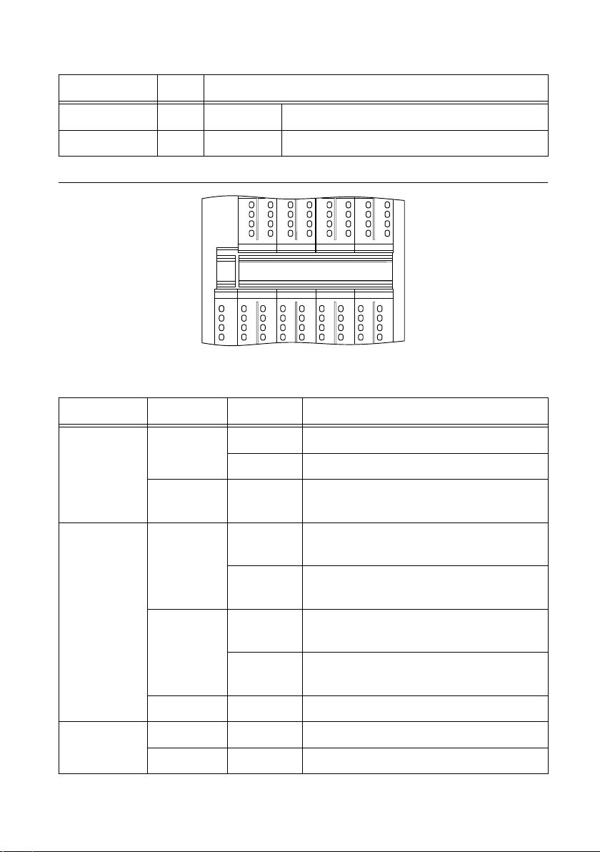
Table 2. REM-11152 Signal Descriptions (Continued)
Signal Color Description
20 to 27, 60 to 67 Blue GND Reference potential for all channels
30 to 37, 70 to 77 Green FE Functional earth ground (FE)
Figure 3. REM-11152 LEDs
D
UI
E1
E2
00 02 04 06
10 12 14 1611 13 15 17
20 22 24 2621 23 25 27
30
41 43 45 47
51 53 55 57
61 63 65 67
71 73 75 77
40 42 44 46
50 52 54 56
60 62 64 66
70 72 74 76
32 34 3631 33 35 37
01 03 05 07
Table 3. LED Indicators
LED LED Color LED Pattern Indication
D
Green
Solid The REM-11152 is ready for operation.
Flashing Data is invalid or unavailable.
Green/Yellow Flashing The REM-11152 cannot communicate with
the connected devices.
D
Yellow
Solid The REM-11152 did not detect a valid cycle
after power-on.
Flashing The REM-11152 is not part of the
configuration.
Red
Solid The REM-11152 has lost connection to the
Bus Coupler.
Flashing The REM-11152 has lost connection to the
preceding adjacent module.
— Off The REM-11152 is in reset mode.
UI
Green Solid Supply to digital output module present.
— Off No supply to digital output modules.
8| ni.com | REM-11152 Getting Started Guide

Table 3. LED Indicators (Continued)
LED LED Color LED Pattern Indication
E1
Red Solid Breakdown or overload/short-circuit of an
output.
— Off No I/O error.
E2
Red Solid Breakdown or overload/short-circuit of an
output.
— Off No I/O error.
00 to 07, 40 to
47
Red Solid Short-circuit/overload of the output.
Yellow Solid Input is set.
— Off Input is not set.
Connecting the REM-11152
24 VDC
DI (0:7)
US(24 V)
GND
FE
REM-11152
FE
GND
US(24 V)
DI (8:15)
+
–
a1
a2
b1
b2
x8
Sourcing-Output
Device
Sourcing-Output
Device
GND
24 V
24 V
FE
GND
FE
• The input signals connect to the DI terminals.
• GND provides a path for the return current to flow.
• US and FE are optional, device-dependent connections.
REM-11152 Getting Started Guide | © National Instruments | 9
Table of contents
Other NI Control Unit manuals


Popular Control Unit manuals by other brands

Festo
Festo Compact Performance CP-FB6-E Brief description

Elo TouchSystems
Elo TouchSystems DMS-SA19P-EXTME Quick installation guide

JS Automation
JS Automation MPC3034A user manual

JAUDT
JAUDT SW GII 6406 Series Translation of the original operating instructions

Spektrum
Spektrum Air Module System manual

BOC Edwards
BOC Edwards Q Series instruction manual

KHADAS
KHADAS BT Magic quick start

Etherma
Etherma eNEXHO-IL Assembly and operating instructions

PMFoundations
PMFoundations Attenuverter Assembly guide

GEA
GEA VARIVENT Operating instruction

Walther Systemtechnik
Walther Systemtechnik VMS-05 Assembly instructions

Altronix
Altronix LINQ8PD Installation and programming manual


