Nibe Drazice REU 18-2,5 Specification sheet

OPERATING AND
INSTALLATION MANUAL
BUILT-IN ELECTRIC FLANGE HEATING UNIT
REU 18 - 2,5
RDU 18 - 2,5
RDU 18 - 3
RDU 18 - 3,8
RDU 18 - 5
RDU 18 - 6
RDW 18 - 7,5
RDW 18 - 10
RSW 18 - 12
RSW 18 - 15
SE 377
SE 378
Družstevní závody Dražice - strojírna s.r.o.
Dražice 69, 294 71 Benátky nad Jizerou
Phone.: +420 /326 370 990
Fax: +420 / 326 370 980
E-mail: expo[email protected]z

- 2 -
CONTENTS
1PRODUCT TECHNICAL SPECIFICATION....................................................................................................... 4
2ENERGY SAVING......................................................................................................................................... 4
3OPERATION AND TEMPETATURE SETTING................................................................................................ 4
4OPERATION PRECONDITIONS .................................................................................................................... 5
5 ASSEMBLY AND SAFETY INSTRUCTIONS .................................................................................................... 5
5.1 GENERAL INSTRUCTIONS................................................................................................................... 5
5.2 INSTALATION SCHEME....................................................................................................................... 7
5.3 HEATING UNIT ASSEMBLY ................................................................................................................. 8
5.4 ANTI-CORROSION PROTECTION INSTRUCTIONS ............................................................................... 9
5.5 ACCUMULATOR CONNECTION TO THE PRESSURIZED WATER MAIN................................................ 9
5.6 ELECTRICAL CONNECTION ............................................................................................................... 10
5.7 FIRST PUTTING INTO OPERATION.................................................................................................... 14
6INSPECTION, CARE, MAINTENANCE ........................................................................................................ 14
7FUNCTIONAL DEFECTS............................................................................................................................. 14
8TECHNICAL DATA ..................................................................................................................................... 15
9DISPOSAL OF PACKAGING MATERIAL AND NON-FUNCTIONING PRODUCT............................................ 16

- 3 -
CAREFULLY READ THIS MANUAL BEFORE INSTALLING THE WATER HEATER!
Dear Customers!
The “R” heating element series by HPA Switzerland (Switzerland) and the “SE” series of heating elements
by Winkelmann GmbH, Stahl-Behalter-Technik (Germany) are manufactured and tested accordingly
with the valid ÖVE or VDE safety regulations.
Their installation and putting into operation may only be implemented by assembly companies, following
this manual.
In this manual, you can find all important instructions necessary for proper installation and operation. Despite
that, have the element installation, operation, and functions demonstrated and explained.
Naturally, our department is at your service: Service and Sales Dept.
The product is not intended to be controlled by
a) people (including children) with reduced physical, sensual or mental capacities, or
b) people with insufficient knowledge and experiences unless supervised by responsible person,
or unless properly instructed by such responsible person.
The manufacturer reserves the right for engineering modification of the product. The product is designed
for permanent contact with drinkable water.
It is recommended to use the product in indoor environment with air temperatures from +2°C to 45°C
and a relative humidity up to 80%.
Meaning of pictograms used in the Manual
Important information for heater users.
Abiding by the recommendations of the manufacturer serves to ensure trouble-free operation
and the long service life of the product.
Caution!
Important notice to be observed.

- 4 -
1PRODUCT TECHNICAL SPECIFICATION
The R and SE series built-in electric flange heating units as main heaters for electric boilers are self-servicing.
If calcium rich water is used, scale needs to be removed from the heating element in given time intervals.
The user may set a temperature on the thermostat. The element is turned on automatically; after reaching
set water temperature, it is turned off. If the temperature drops (e.g. either by water consumption or natural
cooling), the unit is turned on and heated to the pre-set temperature.
2ENERGY SAVING
Low water temperature in the boiler proves to be especially economic. Therefore the temperature should
be set to be adequate for intended hot water consumption, not higher. This helps to save electricity
and prevents lime sediment occurrence.
3OPERATION AND TEMPETATURE SETTING
The temperature of water in the heater can be adjusted as needed by the thermostat, either continuously
or in three steps as indicated. This allows energetically economic operation. To set the temperature, 3 main
marked symbols are used:
•Accumulator freezing protection
•Approx. 40 °C, water temperature for washing hands
•Approx. 65 °C, hot water - to prevent scalding, this degree is recommended as it is the economic
operation with minimum energy loss and minimum scale occurrence
When the thermostat button is in the utmost left position, this is not the zero position nor is the
heating turned off.
During day mode operation, the thermostat should not be set to temperatures above 65°C.

- 5 -
4OPERATION PRECONDITIONS
The connection of a built-in electric flange unit must follow the data on the plate (operation
pressure, heating time, el. voltage). Connecting to the electrics must follow the scheme
on the inside of the protective cover.
Aside from the electric regulations, the conditions of local distribution and water supply plants,
as well as assembly and operation conditions, must be followed.
If the water is really hard, we recommend installation of water treatment filters preventing
the scale occurrence.
These heating elements are suitable for enamelled accumulators, double casing tanks, or accumulators
coated with either plastic or zinc; they are also suitable for ribbed exchangers. Combination with chromium–
nickel vessels is problematic, and therefore not recommended (see par. 5.3). All elements are suitable
for heating drinkable and heating water with operating pressure within 10 bar.
5ASSEMBLY AND SAFETY INSTRUCTIONS
5.1 GENERAL INSTRUCTIONS
During operation, both the heating element and the anode rod must be under water. Necessary thermal flow
of heated water must not be prevented. The heating unit is equipped with a safety fuse preventing further
water heating at maximum temperature of 120 ºC. It is therefore necessary to select suitable connecting
components (pipelines, safety valve combination) that, in case of thermostat defect, resist
the max. temperature of 120 °C.
Both the assembly and installation must be implemented by authorised people only.
Both electric and water installation must follow and meet requirements and regulations
relevant in the country of use.

- 6 -
Position of installation of elements of series: R, SE
Correct Faulty
Too long flange welded too high.
Thermowell under the heating element.
Vertical installation from the bottom
Only R and SE types
Correct Faulty
The unit built in too high and in reversed
position (the protective guard is up).

- 7 -
The flange rim must not exceed 130 mm, so that the temperature sensor and the element reach
into the tank deep enough. Correct position of a built-in element assures even heating
of the tank contents. In front of the flange, a +100 mm free space must be left for the assembly.
Scale occurrence lowers functionality; it is therefore necessary, especially with hard water, to take
the following measures: Select proper temperature setting; install device lowering water hardness; regular
removal of boiler scale.
Damage to the heating element due to calcareous sediments is not accepted
by the manufacturer as a reason for complaint.
5.2 INSTALATION SCHEME
The number of elements differs according to type line.
For the R, SE type series

- 8 -
Adequate flanges:
For all types For all types
R…18…( ¤180 ) SE 377, SE 378 ( ¤255 )
8 holes 10 holes
5.3 HEATING UNIT ASSEMBLY
Aside from the installation regulations, the conditions of connection resulting from local distribution and
water supply plants must be followed:
1. Remove protective cover, position 1
2. Install heating flange with the seal (position 2.3) into the tank (Fig. 3). The thermowell must always
be above the heating element well
3. Fit the heating flange (position 2) using M8 screws (max. tightening torque 22 Nm), tightened
crosswise; Screwing the heating element must be tested and tightened with a 2 - 3 Nm tightening
torque
4. Implement electric connection following the scheme (see point 5.6). Warning - do not forget
to connect the guard wire
5. Fit the protective cover and tighten with a nut, fit the control wheel of the thermostat
6. Put into operation only if water is in the accumulator
Heating element assembly and its initial operation can only be implemented by an expert,
who takes responsibility for proper implementation and equipment.

- 9 -
5.4 ANTI-CORROSION PROTECTION INSTRUCTIONS
Heating unit maintenance involves checking and exchanging of the anode rod that is only contained
in outputs from 2.5 to 6 kW.
Magnesium anode sets the electric potential inside the tank to a level that limits boiler tank corrosion.
Theoretically, its lifetime is calculated to two years of operation; however, it changes based on water
hardness and chemical composition at the place of use. Anode rod check and possible replacement
is recommended every two years of operation. Based on anode wear, set the time of the next check.
We recommend you do not underestimate the importance of this additional protection of the boiler tank.
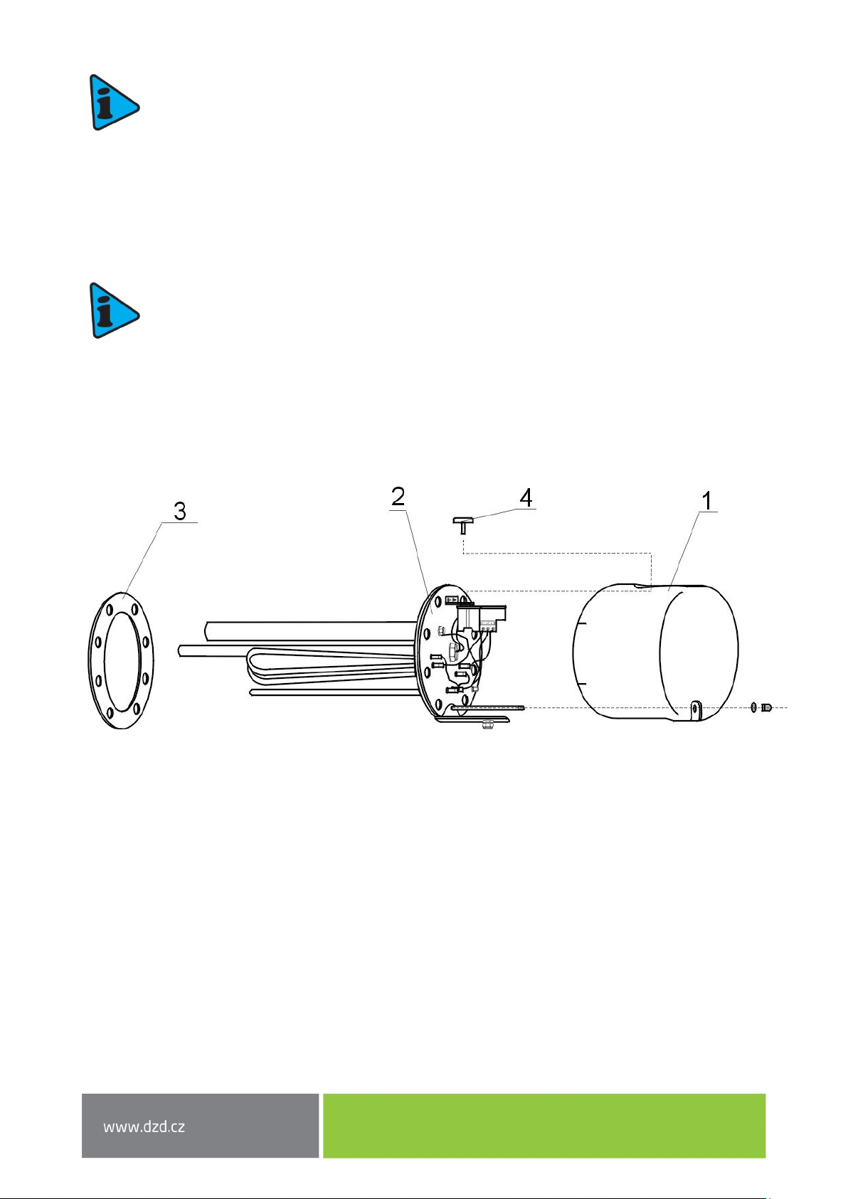
Anode rod exchange method:
1. Turn off the boiler control voltage;
2. Empty the boiler water.
Procedure: Close the water entry valve to the boiler
Open the hot water valve on the mixing tap
Open the boiler drain tap
3. The anode is screwed onto the heating unit
4. Unscrew the anode using adequate wrench
5. Pull the anode out and follow reversed steps to install a new one
6. During the assembly, make sure the ground wire is connected properly; it is essential for proper
anode function
7. Fill the boiler with water
5.5 ACCUMULATOR CONNECTION TO THE PRESSURIZED WATER
MAIN
Accumulator assembly, connection, and use instructions must be followed.
Connection to the Pressure System
If inadequate and non-functional fittings are used and the operational pressure exceeded, the warranty
is cancelled.
Water main connection may only be implemented via a diaphragm safety valve or a diaphragm safety
combination. Safety valve combination consists of a closing valve, pressure reducing valve, test valve,
backflow valve, overload valve with compensation circulation, and a drain valve. This combination is built
in between the cold water inlet and cold water inlet to the reservoir.

- 10 -
5.6 ELECTRICAL CONNECTION
Heating element assembly and its initial operation can only be implemented by an expert,
who takes responsibility for proper implementation and equipment.
The electrical connection must be implemented based on the attached scheme. The scheme
related to a specific type is inside the plastic cover of the heating unit!
The network voltage must be respected! All metal parts of the accumulator must meet
relevant protective regulations.
The main must have a multipole switch with a 3 mm contact clearing. All switches must be
connected to circuit breakers. The lead in cable must be led into the area of connection via
a sealing connector and secured from shifting, wringing, and tearing out by a clamp.
Warning! Factory connection must not be changed.

- 11 -
Connection scheme for SE 377, SE 378
The heating unit allows 3 types of connection.
P = 3,2 kW
Factory connection must not be changed!

- 12 -
Connection scheme
for REU type
1/PE-N ∼230 V
for RDU 2,5 kW – 5kW for RDU 6kW
3/PE ∼400 V for RDW 7,5 kW, 10kW
Star 3/PE ∼400 V
triangle

- 13 -
for RSW 18-12 & RSW 18-15
12/15 kW 3/PE ∼400 V
triangle
Connection is only possible with a contactor, not directly through the thermostat!
wiring of heating element
external connection

- 14 -
5.7 FIRST PUTTING INTO OPERATION
Before electric part connection, the accumulator must be filled with water. During the rating, water must
drip off the safety valve.
Warning: Both the hot water outlet pipe and safety armature parts may be hot.
After heating, the set temperature of consumed water should roughly correspond with temperature shown
on the thermometer.
6INSPECTION, CARE, MAINTENANCE
High calcium content water requires the removal of both scale and calcium sediments after one or two years,
implemented by an expert worker. Cleaning may be implemented through the flange opening; a new seal
must be used during assembly.
Specially enamelled accumulator containers must not get in contact with scale solvents or a lime pump.
Eventually, the container must be thoroughly rinsed; its re-heating must follow the method of the first
putting into operation.
After two years of operation, it is recommended that an expert checks the functionality of the –in-built
magnesium anode.
During the maintenance, protective connection of all metal (conductive) parts of the heater must not be
damaged or removed. Neither mechanical means causing abrasion nor paint thinners (nitro, tricholor, etc.)
can be used for cleaning. It is best to use a wet cloth with couple drops of a neutral cleaning preparation.
7FUNCTIONAL DEFECTS
If the water in the accumulator is not heated, check either the circuit breaker or the fuse and the thermostat
settings.
In all other cases, do not try to remove the defect yourself. Seek either expert or service help. It does not
take much for an expert to remove the defect. When making a repair appointment, report the type and serial
number you find on the performance plate of your heating element.

- 15 -
8TECHNICAL DATA
Flange diameter 180 mm - REU 18, RDU 18, RDW 18, RSW 18
Flange diameter 255 mm - SE 377, SE 378
REU: Single-phase version for direct connection ∼230 V
RDU, RDW, RSW, SE: Three-phase version for direct connection 3 ∼400 V
Types of REU, RDU, RDW and RSW with reduction flange can be used for other water heaters and water
tanks.
Heating time:
Capacity Flange size* Time of heating from 10 °C to 60 °C [hours]
lmm 865 432,5 21,5 1
300
flange ∅150
RDU 18 - 2,5
RDU 18 - 3
RDU 18 - 3,8
RDU 18 - 5
RDU 18 - 6
RDW 18 - 7,5
RDW 18 - 10
RSW 18 - 12
RSW 18 - 15
400 flange ∅150 RDU 18 - 3RDU 18 - 3,8 RDU 18 - 5 RDU 18 - 6RDW 18 - 7,5 RDW 18 - 10 RSW 18 - 12 RSW 18 - 15
500 flange ∅150 RDU 18 - 3,8 RDU 18 - 5 RDU 18 - 6RDW 18 - 7,5 RDW 18 - 10 RSW 18 - 12 RSW 18 - 15
Capacity
Flange size*
Time of heating from 10 °C to 60 °C [hours]
lmm 865 432,5 2
750 flange
∅
150 RDU 18 - 6RDW 18 - 75 RDW 18 - 10 RSW 18 - 12 RSW 18 -15
flange ∅225 SE 377 - 8SE 378 - 9,5 SE 377 - 11 SE 378 - 14 SE 377 - 16 SE 378 - 19
1000
flange
∅
150
RDW 18 - 7,5
RDW 18 - 10
RSW 18 - 12
RSW 18 - 15
flange ∅225
SE 377 - 8
SE 378 - 9,5
SE 377 - 11
SE 378 - 14
SE 377 - 16
SE 378 - 19
Note: Flange diameter 150 and 225 mm = screw spacing
Type Output [kW] Connection
Element lenght
[mm]
Weight [kg]
REU 18 - 2,5 2,5 1 PE-N AC 230 V / 50 Hz 450 3
RDU 18 - 2,5 2,5 3 PE-N AC 400 V / 50 Hz 450 3,3
RDU 18 - 3 33 PE-N AC 400 V / 50 Hz 450 3,4
RDU 18 - 3,8 3,8 3 PE-N AC 400 V / 50 Hz 450 3,5
RDU 18 - 5 53 PE-N AC 400 V / 50 Hz 450 3,5
RDU 18 - 6 63 PE-N AC 400 V / 50 Hz 450 3,5
RDW 18 - 7,5 7,5 3 PE-N AC 400 V / 50 Hz 450 3,7
RDW 18 - 10 10 3 PE-N AC 400 V / 50 Hz 450 4
RSW 18 - 12 12 3 PE-N AC 400 V / 50 Hz 530 4
RSW 18 - 15 15 3 PE-N AC 400 V / 50 Hz 630 4,2
SE 377* 8,0-11-16 3 PE-N AC 400 V / 50 Hz 610 8
SE 378** 9,5-12,7-19 3 PE-N AC 400 V / 50 Hz 750 11,5
* Only for the hot water storage tanks 750 and 1000 liters
** Only for the hot water storage tanks OKCE 750 S and 1000 liters

- 16 -
9DISPOSAL OF PACKAGING MATERIAL AND NON-
FUNCTIONING PRODUCT
A service fee for providing return and recovery of packaging material has been
paid for the packaging in which the product was delivered. The service fee was
paid pursuant to Act No 477/2001 Coll., as amended, at EKO-KOM a.s. The client
number of the company is F06020274. Take the water boiler packages to a waste
disposal place determined by the town. When the operation terminates,
disassemble and transport the discarded and unserviceable heater to a waste
recycling centre (collecting yard), or contact the manufacturer.
15-7-2019
This manual suits for next models
11
Table of contents
Other Nibe Electric Heater manuals
Popular Electric Heater manuals by other brands

Qlima
Qlima EFE 2018 operating manual

AEG
AEG WSP 2010 Operation and installation instructions

Holmes
Holmes HFH109 owner's guide

GHP Group
GHP Group Dyna-Glo HEAT AROUND 360 HA1360RH User's manual and operating instructions

Trotec
Trotec IR 1550 SC operating manual

Noble Heat
Noble Heat Panther 2000 owner's manual