Nibe Drazice TPJ 150-8/2,5 kW Specification sheet

OPERATING AND
INSTALLATION MANUAL
BUILT-IN ELECTRIC FLANGE HEATING UNIT
TPJ 150-8/2,5 kW
TPJ 150-8/3,0 kW
TPJ 150-8/4,0 kW
TPJ 150-8/9,0 kW
TPJ 150-8/12 kW
TPJ 150-8/15 kW
Družstevní závody Dražice - strojírna s.r.o.
Dražice 69, 294 71 Benátky nad Jizerou
Phone.: +420 / 326 370 911
E-mail: [email protected]

- 2 -
CONTENTS
1 PRODUCT TECHNICAL SPECIFICATION....................................................................................................... 4
2 ENERGY SAVING......................................................................................................................................... 4
3 OPERATION AND TEMPETATURE SETTING................................................................................................ 4
4 OPERATION PRECONDITIONS.................................................................................................................... 5
5 ASSEMBLY AND SAFETY INSTRUCTIONS.................................................................................................... 5
5.1 GENERAL INSTRUCTIONS................................................................................................................... 5
5.2 INSTALATION SCHEME....................................................................................................................... 7
5.3 HEATING UNIT ASSEMBLY ................................................................................................................. 8
5.4 ANTI-CORROSION PROTECTION INSTRUCTIONS ............................................................................... 9
5.5 ACCUMULATOR CONNECTION TO THE PRESSURIZED WATER MAIN................................................ 9
5.6 ELECTRICAL CONNECTION............................................................................................................... 10
5.7 FIRST PUTTING INTO OPERATION.................................................................................................... 13
6 INSPECTION, CARE, MAINTENANCE ........................................................................................................ 13
7 FUNCTIONAL DEFECTS............................................................................................................................. 13
8 TECHNICAL DATA..................................................................................................................................... 14
9 DISPOSAL OF PACKAGING MATERIAL AND NON-FUNCTIONING PRODUCT............................................ 15

- 3 -
CAREFULLY READ THIS MANUAL BEFORE INSTALLING THE WATER HEATER!
Dear customer,
The Works Cooperative of Dražice - Machine Plant, Ltd., would like to
thank you for your decision to use a product of our brand.
The product is not intended to be controlled by
a) people (including children) with reduced physical, sensual or mental capacities, or
b) people with insufficient knowledge and experiences unless supervised by responsible person,
or unless properly instructed by such responsible person.
The manufacturer reserves the right for engineering modification of the product. The product is designed
for permanent contact with drinkable water.
It is recommended to use the product in indoor environment with air temperatures from +2 °C to +45 °C
and a relative humidity up to 80 %.
Product’s reliability and safety is proven by tests implemented by the Engineering Test Institute in Brno.
Made in the Czech Republic.
Meaning of pictograms used in the Manual
Important information for heater users.
Abiding by the recommendations of the manufacturer serves to ensure trouble-free operation
and the long service life of the product.
Caution!
Important notice to be observed.

- 4 -
1PRODUCT TECHNICAL SPECIFICATION
The TPJ serie built-in electric flange heating units as main heaters for electric boilers are self-servicing.
If calcium rich water is used, scale needs to be removed from the heating element in given time intervals.
The user may set a temperature on the thermostat. The element is turned on automatically; after reaching
set water temperature, it is turned off. If the temperature drops (e.g., either by water consumption or natural
cooling), the unit is turned on and heated to the pre-set temperature.
2ENERGY SAVING
Low water temperature in the boiler proves to be especially economic. Therefore, the temperature should
be set to be adequate for intended hot water consumption, not higher. This helps to save electricity
and prevents lime sediment occurrence.
3OPERATION AND TEMPETATURE SETTING
The temperature of water in the heater can be adjusted as needed by the thermostat, either continuously
or in three steps as indicated. This allows energetically economic operation. To set the temperature, 3 main
marked symbols are used:
•Minimum setting - frost protection (approx. 2 °C to 10 °C)
•Approx. 60 °C, hot water - to prevent scalding, this degree is recommended as it is the economic
operation with minimum energy loss and minimum scale occurrence
•Maximum setting (approx. 70 °C to 80 °C)
Figure 1

- 5 -
4OPERATION PRECONDITIONS
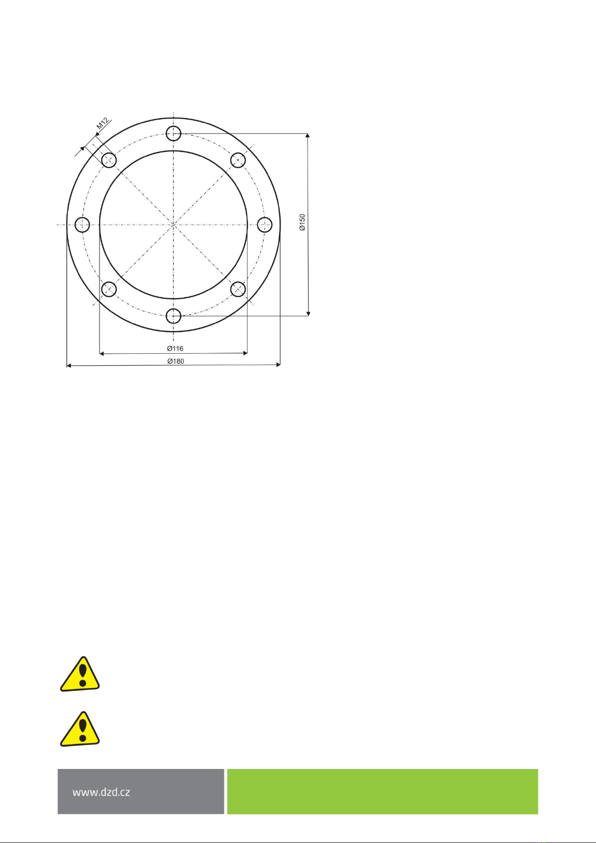
The connection of a built-in electric flange unit must follow the data on the plate (operation
pressure, heating time, el. voltage). Connecting to the electrics must follow the scheme on the
inside of the protective cover.
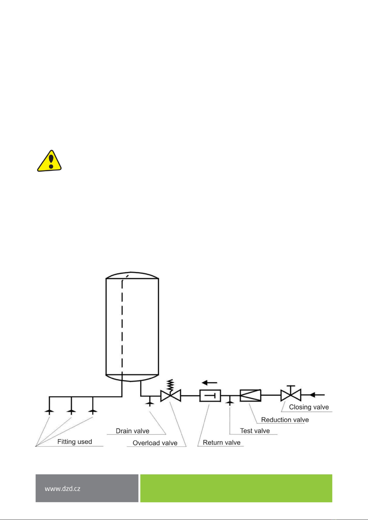
Aside from the electric regulations, the conditions of local distribution and water supply plants,
as well as assembly and operation conditions, must be followed.
If the water is really hard, we recommend installation of water treatment filters preventing
the scale occurrence.
These heating elements are suitable for enameled accumulators, double casing tanks, or accumulators
coated with either plastic or zinc; they are also suitable for ribbed exchangers. Combination with chromium–
nickel vessels is problematic, and therefore not recommended (see par. 5.3). All elements are suitable
for heating drinkable and heating water with operating pressure within 10 bar.
5ASSEMBLY AND SAFETY INSTRUCTIONS
5.1 GENERAL INSTRUCTIONS
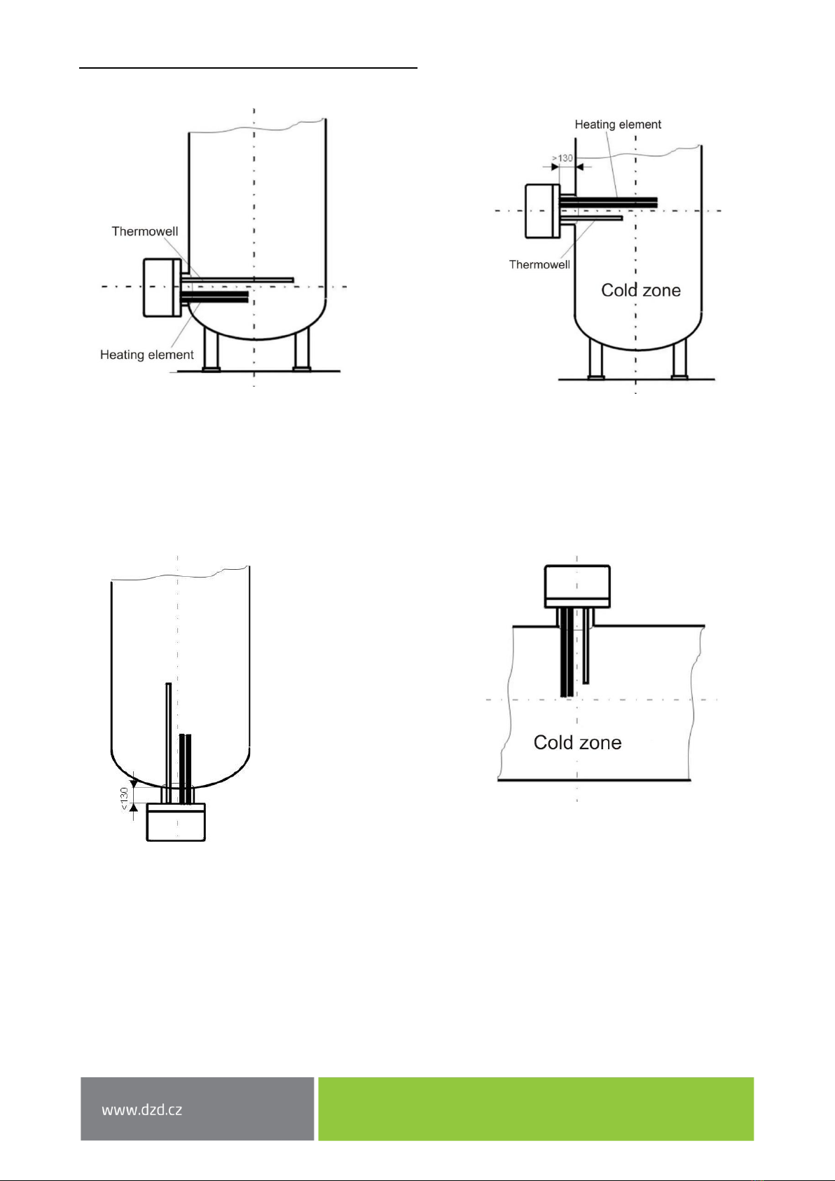
During operation, both the heating element and the anode rod must be under water. Necessary thermal flow
of heated water must not be prevented. The heating unit is equipped with a safety fuse preventing further
water heating at maximum temperature of approx. 95 °C. It is therefore necessary to select suitable
connecting components (pipelines, safety valve combination) that, in case of thermostat defect, resist
the max. temperature of 110 °C.
Both the assembly and installation must be implemented by authorized people only.
Both electric and water installation must follow and meet requirements and regulations
relevant in the country of use.

- 6 -
Position of installation of elements of series: TPJ
Correct Faulty
Too long flange welded too high.
Thermowell under the heating element.
Vertical installation from the bottom
Correct Faulty
The unit built in too high and in reversed
position (the protective guard is up).

- 7 -
The flange rim must not exceed 130 mm, so that the temperature sensor and the element reach
into the tank deep enough. Correct position of a built-in element assures even heating of the
tank contents. In front of the flange, a +100 mm free space must be left for the assembly.
Scale occurrence lowers functionality; it is therefore necessary, especially with hard water, to take
the following measures: Select proper temperature setting; install device lowering water hardness; regular
removal of boiler scale.
Damage to the heating element due to calcareous sediments is not accepted by
the manufacturer as a reason for complaint.
5.2 INSTALATION SCHEME
1 - Protective cover
2 - Heating flange
3 - Sealing ring
4 - Control wheel of the thermostat

- 8 -
Adequate flanges:
For all types
TPJ 150-8 .. (Ø180)
8 holes
5.3 HEATING UNIT ASSEMBLY
Aside from the installation regulations, the conditions of connection resulting from local distribution
and water supply plants must be followed:
1. Remove protective cover, position 1.
2. Install heating flange with the seal (position 2.3) into the tank (Fig. 3). The thermowell must always
be above the heating element well.
3. Fit the heating flange (position 2) using M8 screws (tightening torque 15 - 20 Nm), tightened
crosswise; Screwing the heating element must be tested and tightened (tightening torque 15 -
20 Nm).
4. Implement electric connection following the scheme (see point 5.6). Warning - do not forget
to connect the guard wire.
5. Fit the protective cover and tighten with a nut, fit the control wheel of the thermostat.
6. Put into operation only if water is in the accumulator.
Heating element assembly and its initial operation can only be implemented by an expert,
who takes responsibility for proper implementation and equipment.
The space in front of the connection armature equal to the installation length + 50 mm must
be left free for installation, etc.

- 9 -
5.4 ANTI-CORROSION PROTECTION INSTRUCTIONS
Magnesium anode sets the electric potential inside the tank to a level that limits boiler tank corrosion.
Theoretically, its lifetime is calculated to two years of operation; however, it changes based on water
hardness and chemical composition at the place of use. Anode rod check and possible replacement
is recommended every two years of operation. Based on anode wear, set the time of the next check.
We recommend you do not underestimate the importance of this additional protection of the boiler tank.
5.5 ACCUMULATOR CONNECTION TO THE PRESSURIZED WATER
MAIN
Accumulator assembly, connection, and use instructions must be followed.
Connection to the Pressure System
If inadequate and non-functional fittings are used and the operational pressure exceeded, the warranty
is cancelled.
Water main connection may only be implemented via a diaphragm safety valve or a diaphragm safety
combination. Safety valve combination consists of a closing valve, pressure reducing valve, test valve,
backflow valve, overload valve with compensation circulation, and a drain valve. This combination is built
in between the cold water inlet and cold water inlet to the reservoir.

- 10 -
5.6 ELECTRICAL CONNECTION
Heating element assembly and its initial operation can only be implemented by an expert,
who takes responsibility for proper implementation and equipment.
The electrical connection must be implemented based on the attached scheme. The scheme
related to a specific type is inside the plastic cover of the heating unit!
The network voltage must be respected! All metal parts of the accumulator must meet
relevant protective regulations.
The main must have a multipole switch with a 3 mm contact clearing. All switches must be
connected to circuit breakers. The lead in cable must be led into the area of connection via
a sealing connector and secured from shifting, wringing, and tearing out by a clamp.
Warning! Factory connection must not be changed.
Connection scheme
for TPJ 150-8/2,5 kW
1/PE-N 230 V

- 11 -
for TPJ 150-8/3,0 kW - 4,0 kW
3/PE 3 x 230 V
Star
for TPJ 150-8/9,0 kW
3/PE 400 V
Triangle

- 12 -
for TPJ 150-8/12 kW - 15 kW
12/15 kW 3/PE 400 V
Triangle
Connection is only possible with a contactor, not directly through the thermostat!
wiring of heating element
external connection

- 13 -
5.7 FIRST PUTTING INTO OPERATION
Before electric part connection, the accumulator must be filled with water. During the rating, water must
drip off the safety valve.
Warning: Both the hot water outlet pipe and safety armature parts may be hot.
After heating, the set temperature of consumed water should roughly correspond with temperature shown
on the thermometer.
6INSPECTION, CARE, MAINTENANCE
High calcium content water requires the removal of both scale and calcium sediments after one or two years,
implemented by an expert worker. Cleaning may be implemented through the flange opening; a new seal
must be used during assembly.
Specially enamelled accumulator containers must not get in contact with scale solvents or a lime pump.
Eventually, the container must be thoroughly rinsed; its re-heating must follow the method of the first
putting into operation.
After two years of operation, it is recommended that an expert checks the functionality of the –in-built
magnesium anode.
During the maintenance, protective connection of all metal (conductive) parts of the heater must not be
damaged or removed. Neither mechanical means causing abrasion nor paint thinners (nitro, tricholor, etc.)
can be used for cleaning. It is best to use a wet cloth with couple drops of a neutral cleaning preparation.
7FUNCTIONAL DEFECTS
If the water in the accumulator is not heated, check either the circuit breaker or the fuse and the thermostat
settings.
In all other cases, do not try to remove the defect yourself. Seek either expert or service help. It does not
take much for an expert to remove the defect. When making a repair appointment, report the type and serial
number you find on the performance plate of your heating element.

- 14 -
8TECHNICAL DATA
Flange diameter 180 mm
Type of TPJ with reduction flange can be used for other water heaters and water tanks.
Heating time:
Capacity
Flange size*
Time of heating from 10 °C to 60 °C [hours]
l
mm
8
6
5
4,5
3,5
2,5
2
1,5
1
300
flange ∅150
-
TPJ 150-8/
3,0 kW
-
TPJ 150-8/
4,0 kW
-
-
TPJ 150-8/
9,0 kW
TPJ 150-8/
12 kW
TPJ 150-8/
15 kW
400
flange ∅150
TPJ 150-8
/3,0 kW
TPJ 150-8/
4,0 kW
-
-
-
TPJ 150-8/
9,0 kW
TPJ 150-8/
12 kW
TPJ 150-8/
15 kW
-
500
flange ∅150
TPJ 150-8/
4,0 kW
-
-
-
TPJ 150-8/
9,0 kW
TPJ 150-8/
12 kW
TPJ 150-8/
15 kW
-
-
Capacity
Flange size*
Time of heating from 10 °C to 60 °C [hours]
l
mm
7
6
5
4
3
750
flange ∅150
-
-
TPJ 150-8/
9,0 kW
TPJ 150-8/
12 kW
TPJ 150-8/
15 kW
1000
flange ∅150
TPJ 150-8/
9,0 kW
-
TPJ 150-8/
12 kW
TPJ 150-8/
15 kW
-
Note: Flange diameter 150 = screw spacing
Type
Output
[kW]
Connection
Recommended
breaker [A]
Element length
[mm]
Weight [kg]
TPJ 150-8/2,5 kW
2.5
1 PE-N AC 230 V / 50 Hz
16
450
3
TPJ 150-8/3,0 kW
3
3 PE-N AC 3x 230 V / 50 Hz
3 x 10
450
3.5
TPJ 150-8/4,0 kW
4
3 PE-N AC 3x 230 V / 50 Hz
3 x 10
450
3.5
TPJ 150-8/9,0 kW
9
3 PE-N AC 400 V / 50 Hz
3 x 20
450
4
TPJ 150-8/12 kW
12
3 PE-N AC 400 V / 50 Hz
3 x 20
450
4
TPJ 150-8/15 kW
15
3 PE-N AC 400 V / 50 Hz
3 x 25
580
4.2

- 15 -
9DISPOSAL OF PACKAGING MATERIAL AND
NON-FUNCTIONING PRODUCT
A service fee for providing return and recovery of packaging material has been
paid for the packaging in which the product was delivered. The service fee was
paid pursuant to Act No 477/2001 Coll., as amended, at EKO-KOM a.s. The client
number of the company is F06020274. Take the water boiler packages to a waste
disposal place determined by the town. When the operation terminates,
disassemble and transport the discarded and unserviceable heater to a waste
recycling center (collecting yard), or contact the manufacturer.
19-4-2023
This manual suits for next models
5
Table of contents
Other Nibe Electric Heater manuals
Popular Electric Heater manuals by other brands

Dimplex
Dimplex PLX 500 Installation and operating instructions

Holmes
Holmes AccuTemp HFH595-CN owner's guide

habitat et jardin
habitat et jardin 1536-128810 manual

Gabarron
Gabarron ECO1 Installation manual and user's guide

Euromatic
Euromatic RH24W instruction manual

Soleus Air
Soleus Air HM5-15R-32 owner's manual

Cooper & Hunter
Cooper & Hunter DOMESTIC CH-1000 EC instruction manual

Twin Star Home
Twin Star Home SH-003-BL Operation manual

MrHeater
MrHeater Hero quick guide

Holmes
Holmes HCH5250B owner's guide

HydroMatik
HydroMatik HeaterCompact manual

ClimateMaster
ClimateMaster AG Series Installation, operation and maintanance manual