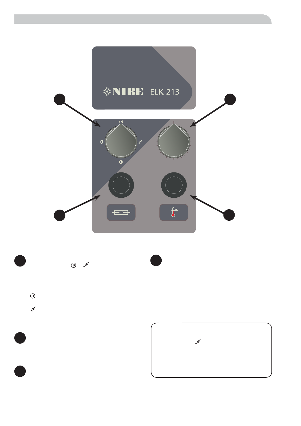
5NIBE ELK 213
For the Installer
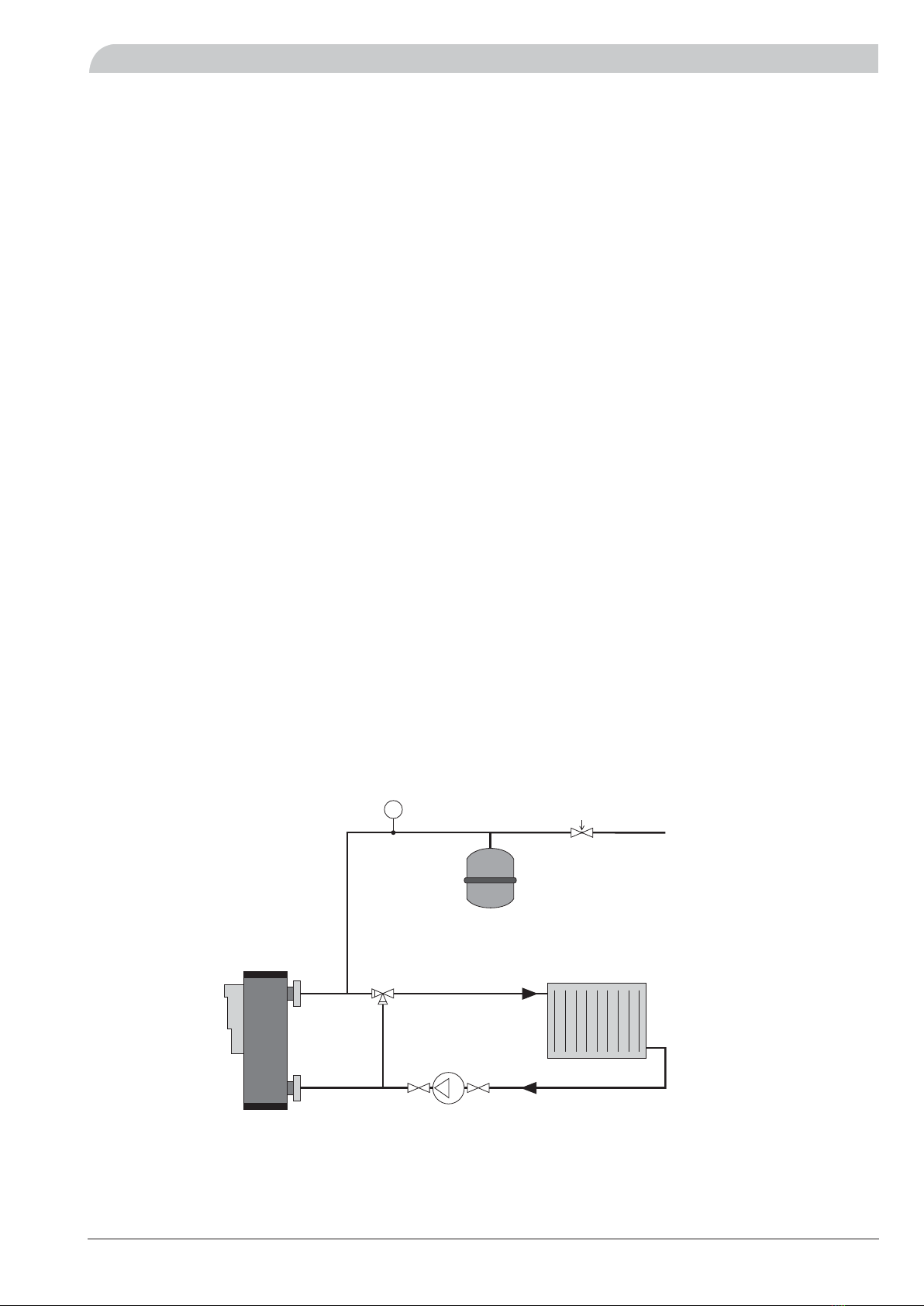
Pipe installation
Pipe installation
500
200
Connection
Install the immersion heater so that external heating does
not cause overheating, for example, in front of the hearth
door (to prevent flames blowing out) or next to the flue
(to prevent damaging heat radiation). A suitable location
is normally at the side of the boiler, directly on the double
jacketed heater’s flanges or similar location.
The pipe installation must be carried out in accordance
with current norms.
The immersion heater is designed for upright installation.
For servicing, immersion heater replacement, miniature
circuit breaker or temperature limiter resetting as well as
draining, 200 mm of space is required in front of the heat-
er’s control panel and 500 mm above the heater (see fig.).
If the above stated spaces cannot be achieved, detachable
connections must be used.
Circulation pump must be used. Pipe dimensions can then
be reduced to R25 with welded sleeves. The immersion
heater can be installed in double jacketed water heaters of
the SP or SPIS type, see installation option 3, (self-
circulation is required).
For follow-up operation, it is recommended to install a
thermometer between the immersion heater and the ap-
paratus that is to be heated, so that the outgoing water
temperature from the immersion heater can be read off.
As the immersion heater is installed on the existing wood
boiler and is solely responsible for the heating demand,
the flue should be sealed. This is most appropriately done
using a plastic bag filed with mineral wool, stuffed into the
hearth, as well as a cover on the opening of the flue.
In closed boiler installations, one of the Swedish Work
Environment Authority’s approved safety valves must be in-
stalled in an open connection with the boiler’s (immersion
heater’s) highest part, however, not directly on the boiler.
The connection line must rise continuously. The safety
valve must be “exercised” regularly, at least 4 times per
year by being opened and closed again quickly. The pres-
sure is then reset by filling with water.
Pipe line between heater and open expansion vessel must
be routed upwards and must not be able to be closed.
Draining
The system is most easily drained by installing a drainage
valve at the lowest point on the pipe installation. Draining
through such a valve leaves a small amount of water in
the immersion heater, which must therefore be drained
through the rain connection (17). If the installation is nor-
mally drained through the immersion heater’s drain con-
nection, install a suitable drainage valve.
The pipe work must be flushed
before the immersion heater is con-
nected, so that any contaminants do
not damage the components parts.
Note!
Before draining the immersion
heater,
cut the power supply.
Note!