General information for the installer
Function
Area of use for NIBE immersion heater is in combination with
NIBE ground source heat pumps and air/water heat pumps.
When the heating demand is greater then heat pump's ca-
pacity, the immersion heater connects automatically as addi-
tional heat. The electrical equipment is adapted to the heat
pump's function.
ELK 15 contains overheating protection and contactors to
externally regulate the two power steps, 5 and 10 kW. For
optimum function the outputs should be binary controlled,
i.e. 5, 10 and 15 kW.
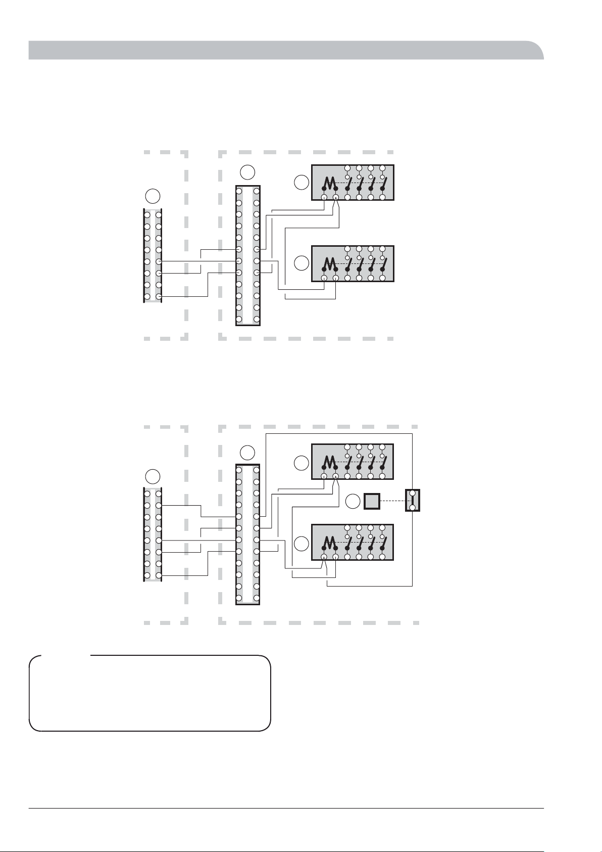
If there is no operating voltage from the heat pump, the
largest power stage can be force controlled via thermostat.
See the wiring diagram.
Pipe installation
The pipe installation must be carried out in accordance with
applicable standards.
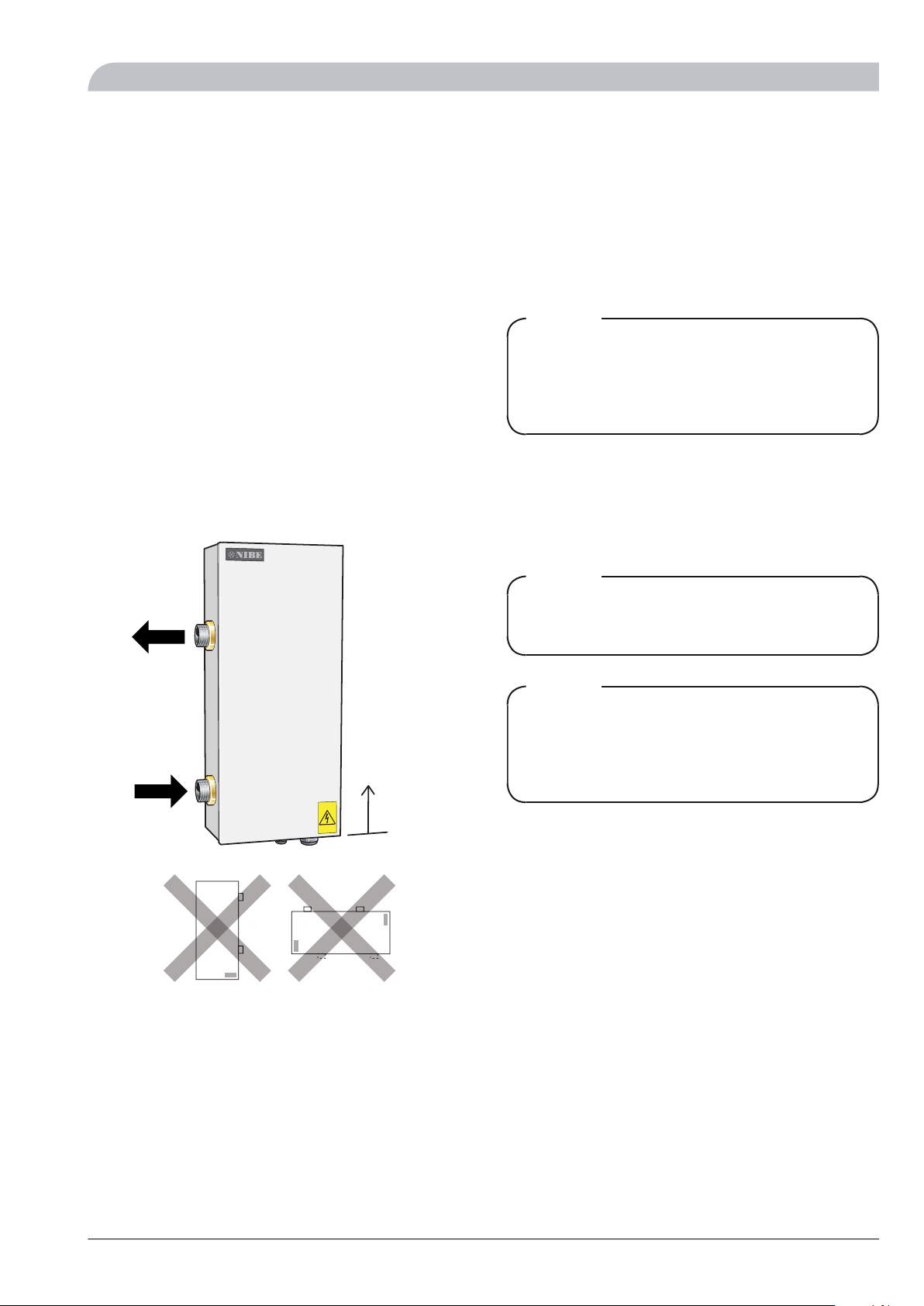
LEK
The immersion heater must be installed standing (see image
above). An area of 500 mm is required in front of the immer-
sion heater for service work. If this is not possible, detachable
connections should be used.
Circulation pump must be used to ensure the flow over the
immersion heater. If the heating system’s valves can close
the circulation completely, a by-pass must be installed to
prevent the flow through the immersion heater from being
stopped. When the unit is off, an approved safety valve must
be installed as well as a pressure expansion vessel. The safety
valves must be checked about four times a year. This is done
by quickly opening and closing the valves. The pressure is
reset by filling with water.
Electrical installation
ELK 15 must be installed via an isolator switch with a minim-
um breaking gap of 3 mm.
NOTE
Electrical installation and service must be carried out
under the supervision of a qualified electrician. Electric-
al installation and wiring must be carried out in accord-
ance with the stipulations in force.
Power supply
The electric heater must be supplied with 4x6mm
2cable,
3 x 400 V AC 50Hz, fused3x25A.
The cable for the operational supply must be 5 x 1,5 mm2.
NOTE
Reset the temperature limiter, it may have tripped
during transport.
NOTE
In the event of any servicing all electrical supplies must
be checked and disconnected. The immersion heater
can be supplied with voltage from connected heat
pump.
Draining
The system is most easily drained by installing a drain valve
to the lowest point of the piping. Draining via such a valve
leaves a small amount of water in the immersion heater,
which is therefore drained via drain connection (71). If the
unit is normally drained via the immersion heater's drain
connection, install a suitable drain valve.
5ELK 15
For the Installer
General information for the installer