manuals.online logo
Brands
  1. Home
  2. •
  3. Brands
  4. •
  5. NIVELCO
  6. •
  7. Transmitter
  8. •
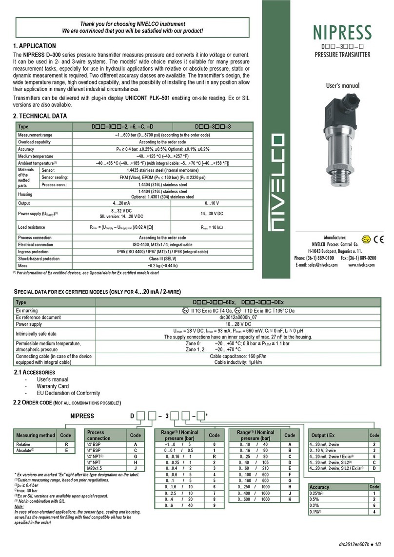
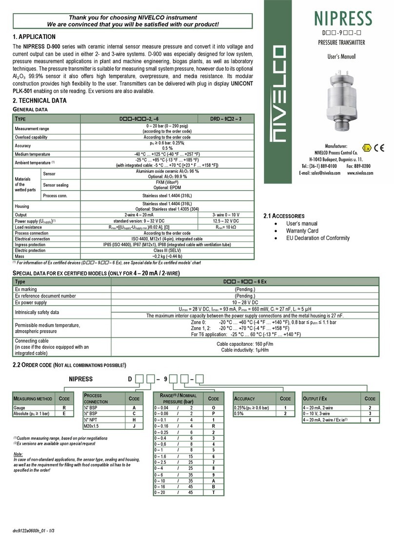
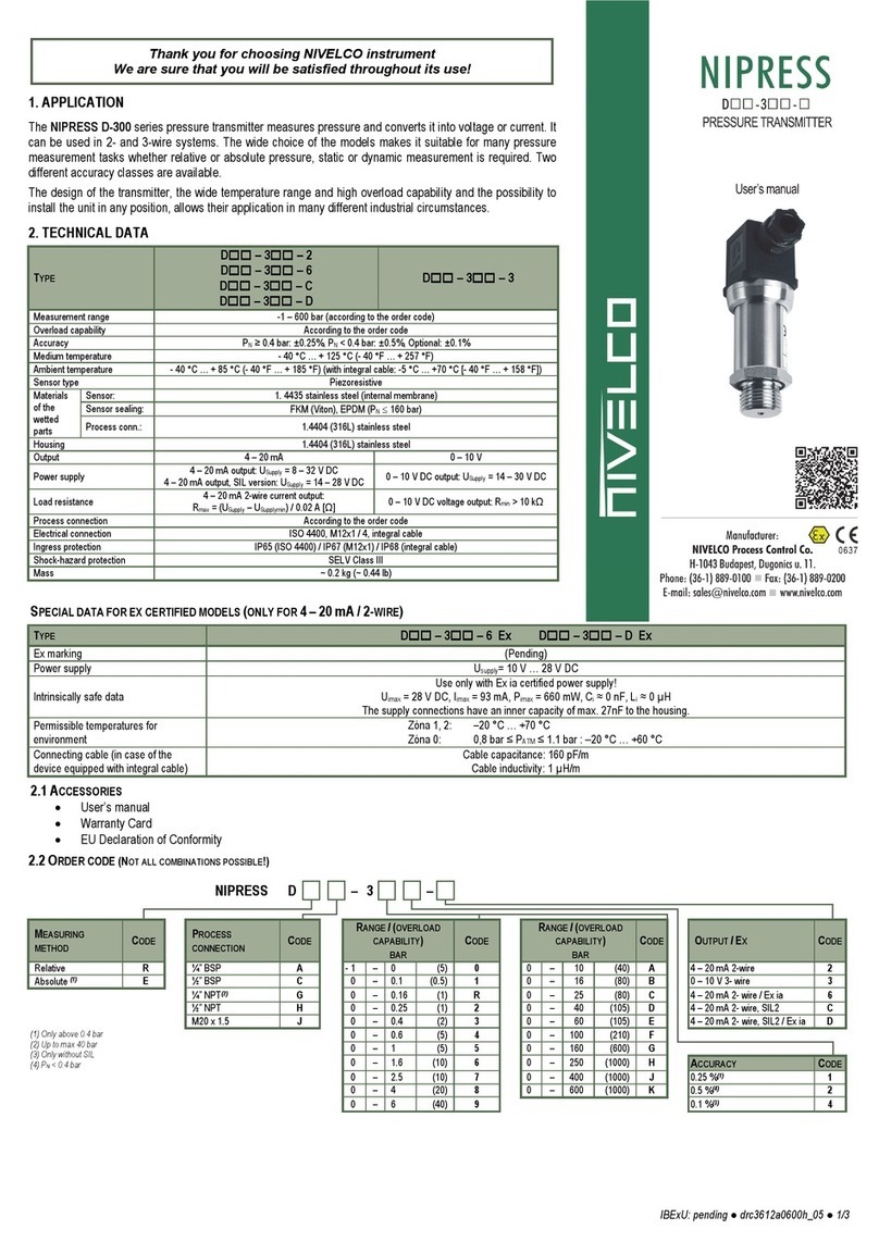
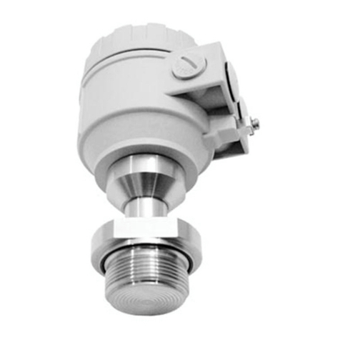
  9. NIVELCO NIPRESS DD-6 Seies User manual

NIVELCO NIPRESS DD-6 Seies User manual

ddr6222a0600h_01
Thank you for choosing NIVELCO instrument.
We are convinced that you will be satisfied with our product!
1. INTRODUCTION
The NIPRESS DD series differential pressure transmitters measure pressure and convert it into voltage or current. DD-600
family uses piezoresistive silicon sensor, has various measuring ranges up to 1000 mbar. Wall mounted design, suitable for
measuring dry, non-aggressive gases and compressed air. This device is short circuit protected against inverse polarity as
well.
The NIPRESS DD-600 can be used for a wide range of different HVAC applications. Its robust design can be used in
laboratories or under industrial conditions. Preferred areas of use are heating, ventilation and air conditioning systems, clean
room and medical technology, filtering technology and draft metering checks.
2. TECHNICAL SPECIFICATION
2.1 GENERAL DATA
Type DD-6-
Measurement range 0 – 1000 mbar according to the order code
Overload capability According to the order code
Accuracy for PN≥6 mbar: ≤±0.5% of full-scale output
for PN< 6 mbar: ≤±1% of full-scale output
Medium temperature 0 °C … +50 °C (32 °F … +122 °F)
Ambient temperature
Sensor type Piezoresistive
Materials of
the wetted
parts
Sensor Piezoresistive silicon sensor
Process
connection Brass nickel plated, PVC / silicone tube (inside the device)
Ház anyaga ABS
Kimenet current or voltage
Power supply
2-wire 4 – 20 mA
current output
Without automatic zero adjustment:
USupply = 11 – 32 V DC
With automatic zero adjustment:
USupply = 24 – 32 V DC
3-wire
0 – 10 V / 0 – 5 V
4 – 20 mA / 0 – 20 mA
switchable output
Without automatic zero adjustment:
USupply = 19 – 32 V DC
With automatic zero adjustment:
USupply = 24 – 32 V DC
Load
resistance
2-wire current output 
Supply Supply min.
max
UU
R0.02 A ,[]
3-wire voltage output Rmin = 10 k
current output Rmax = 330 
Contact output
(optional)
2-wire 2x PNP open collector contact, max. 125 mA (short-circuit proof)
3-wire 2x relay-output (NO/NC) 60 V DC, 40 V AC, max. 1 A
Display
(optional)
2-line LCD display, visible range 32.5 x 22.5 mm; 5-digit 7 segment main display,
digit size 8 mm, range of indication: ±9999; 8-digit 14 segment additional display,
digit size 5 mm; 52 segment bargraph; accuracy: 0.1% ±1 digit
Process connection According to the order code
Electrical connection Cable gland M16x1.5
Ingress protection IP54
Electric protection Class III (SELV)
Mass ~0.2 kg (0.44 lb)
2.2 ACCESSORIES
User’s manual
Warranty Card
EU Declaration of Conformity
2.3 ORDES CODE (NOT ALL COMBINATIONS POSSIBLE!)
NIPRESS D D
– 6
–
PROCESS CONNECTION CODE MEASURING RANGE
/
(MAX.STATC PRESSURE)mba
r
CODE ACCURACY CODE OUTPUT CODE
Ø6.6 x 11; for flex tube Ø6 P0
–
1.6 / 200 R0.5% (p ≥6 mbar) 2 4
–
20 mA, 2-wire 2
Ø4.4 x 10; for flex tube Ø4 R0
–
4 / 200 S1% (p < 6 mbar) 3 0
–
10 V, 3-wire 3
0
–
10 / 200 2
0
–
40 / 345 6
0 – 250 / 1000 C
0 – 1000 / 3000 F
ddr6222a0600h_01
2.4 DIMENSIONS
3. INSTALLATION INSTRUCTION
The device has been calibrated in vertical position, when process connections are
oriented downwards. If it is differently mounted, a tiny deviation from zero point may
appear at. This deviation can be compensated by the “A” potentiometer.
This setting does not change the calibration of the device. In case of outdoor
installation, we suggest to use protective cover against moisture and splashy water
to avoid any potential failures due to inadequately tightened screws.
Install the device only in depressurized and disconnected state!
After removing the front cover pull the cable through the gland and connect it to the
X1 terminal strip with correct wiring. Tighten the gland screw firmly for proper
sealing. Once the wires connected, reinstate the front cover.
Attention! Do not blow into the pressure ports!
This may damage the device.
Initial start-up
After turning on the power supply, the output signal can be measured. Variations in
the output signal may have two possible causes:
1. The idling of the sensor is about 30 min. After this period, the sensor
signal should be stable for zero pressure difference and constant
ambient temperature.
2. For small pressure ranges, slight deviation from the zero-point due to
ambient conditions may occur. This error can be corrected by adjusting
the zero-point potentiometer of the sensor after the idling time is passed.
(Set the output signal of the sensor to the nominal value with both
pressure inputs open.)
4. WIRING
An accidental touch of the inner terminal strip may cause electrostatic discharge
which may result in the failure of the device. To avoid this, please touch any
grounded points before opening the device.
2-wire current output 2-wire current / voltage output
with 2 contacts
3-wire current output 3-wire current / voltage output
with 2 contacts
Wiring
X1 terminal strip 2-wire system
Wiring
X1 terminal strip 3-wire system
2-wire 4 – 20 mA 3-wire 0 – 10 V / 0 – 20 mA
USupply+ 1 NO2 1
USupply
–
2 C2 2
Signal1 3 NC2 3
Signal2 4 NO1 4
C1 5
NC1 6
U
Supply
–
7
U
Supply+ 8
I
OUT 9
U
OUT 10
A. Potentiometer to adjust damping. The damping of the device can be set by
turning a size 2 Phillips screwdriver in the area of 0 – 5000 ms.
B. Display (Optional)
C. Cable Gland M16x1.5
D. Negative pressure connection
E. Positive pressure connection
F. Menu buttons for zeroing: keep on pressing the left menu button for at least
1 second.
G. Configuration Switching (see 5.1 Configuration Switch)
ddr6222a0600h_01
4.1 EXAMPLES OF ARRANGEMENTS
Wiring of 2-wire differential pressure transmitters
Wiring of 3-wire differential pressure transmitters
5. PROGRAMMING
5.1 CONFIGURATION SWITCH
3-wire system
1 2 3 4
Off 0– 10 V / 0 – 20 mA
On 0– 5 V / 4 – 20 mA
Off Automatic zero adjustment off
On Zero adjustment active at start and for 24 h
Off Off Nominal pressure range
1.6 4 10 40 250 1000
On Off Customized ranges
1.0 2.5 6 25 60 400
Off On 160 600
2-wire system
1 2 3 4
Of
f
Of
f
A
utomatic zero adjustment off
On Of
f
Zero adjustment active at start
Of
f
On Zero adjustment active at start and for 24 h
On On Zero adj. active at start, then every 7 days
Off Off Nominal pressure range
1.6 4 10 40 250 1000
On Off Customized ranges
1.0 2.5 6 25 60 400
Of
f
On 160 600
Switches 1 and 2 don't have any functions at special pressure ranges.
5.2 STRUCTURE OF THE MENU SYSTEM
ddr6222a0600h_01
5.3 DESCRIPTION OF THE MENU SYSTEM
Menu Description
Activation By pressing the right-hand key.
Menu 1
HI
Displays the maximum value since the previous start
Available option: Delete value (CLEAR no / yes) (deletes the
upper and lower maximum value)
To delete the value: Press the left-hand key ►A "CLEAR?"
message start flashing in the bottom line, while in the upper line
a "no" message is displayed; you can select between "yes" and
"no" with the right-hand key. Confirm the selection with the left-
hand key.
Menu 2
Lo
Displays the minimum value since the previous start
Available option: Delete value (CLEAR no / yes) (deletes the
upper and lower minimum value)
To delete the value: Press the left-hand key ►A "CLEAR?"
message start flashing in the bottom line, while in the upper line
a "no" message is displayed; you can select between "yes" and
"no" with the right-hand key. Confirm the selection with the left-
hand key.
Menu
3 / 4
OUT
1 / 2
MODE
Menu only activated with contacts
Off Deactivated
Hno Hysteresis, normally open
Hnc Hysteresis, normally closed
Fno Window, normally open
Fnc Window, normally closed
OUT flashing in the bottom line, in the upper line the current
setting is displayed, e.g. "Hno"; the contacts can be selected
with the right-hand key. Confirm the selection with the left-hand
key.
SP
FH
Values for set points in %
Setting the set points: press the left-hand key ►"SP %"
message start flashing in the bottom line, while in the upper line
the current value is displayed; it is possible to change the value
with the right-hand key. Confirm the selection with the left-hand
key.
RP
FL
Values for reset points in %
Setting the reset points: press the left-hand key ►"RP %"
message start flashing in the bottom line, while in the upper line
the current value is displayed; it is possible to change the value
with the right-hand key. Confirm the selection with the left-hand
key.
D. ON
Turn-on delay in s
Timing the turning-on of the device delay: press the left-hand
key ►"D. ON s" message start flashing in the bottom line, the
current value is displayed in the upper line; it is possible to
change the value between 0.0 – 120.0 with the right-hand key.
Confirm the selection with the left-hand key.
D. OFF
Return switching delay in s
Setting the return switching delay: press the left-hand key ►
"D. OFF s" message start flashing in the bottom line, while in
the upper line the current value is displayed; it is possible to
change the value between 0.0 ... 120.0 with the right-hand key.
Confirm the selection with the left-hand key.
Menu 5
UNIT
Setting the pressure unit
Units which can be set: [mbar], [bar], [Pa], [hPa], [kPa], [psi],
[Atm], [torr], [mmHG], or [user] (if the USER unit is selected, the
maximum display value that is shown can be set under the
menu item span)
Setting the unit: press the left-hand key ►"unit" message start
flashing in the bottom line, while in the upper line the currently
set unit is displayed; the unit can be selected with the right-hand
key. Confirm the selection with the left-hand key.
Menu 6
SPAN
Span value for display can be set when the user unit is
selected
Setting DP / SPAN: press the left hand key ►"SPAN" is
displayed in the lower line, the currently set value is displayed
in the upper line; by pressing the left hand button again, "DP"
flashes in the lower line, 8.888, e.g. is displayed in the upper
line, the decimal point can be adjusted with the right hand key,
88.88 e.g. Confirm the selection with the left hand key.
"SPAN" message start flashing in the bottom line, while in the
upper line the currently set value is displayed; the position can
be selected with the left-hand key, the corresponding numerical
value can be changed with the right-hand key, the selection is
confirmed with the left-hand key.
Menu Description
Activation By pressing the right-hand key.
Menu 7
Cal. OFS
Calibration of the Offset to the current value
(only for basic versions without automatic zeroing and square
root extraction)
Calibration of the Offset: Press the left-hand key ►
"CAL. OFS?" message start flashing in the bottom line, while in
the upper line the "no" message is displayed; you can select
between "yes" and "no" with the right-hand key. Confirm the
selection with the left-hand key.
Menu 8
Cal. FSO
Calibration of the endpoint (display and analogue output) to
the current pressure level.
Calibration of the endpoint: Press the left-hand key ►"CAL.
FSO?" message start flashing in the bottom line, while in the
upper line "no" message is displayed; you can select between
"yes" and "no" with the right-hand key. Confirm the selection
with the left-hand key.
Menu 9
TRANSFER
Square-root extraction output signal
(only at square root extraction versions with LCD display)
Lin Standard
–
Linear
root y = x^0.5
cut off 0 – 10%
root3 y = x^1.5
root5 y = x^2.5
Menu 10
AUTOZERO
Menu only visible if zeroing value is visible (Value is read-
only! Setting only possible via configuration switch.)
(only at automatic zeroing versions)
Off no automatic zero adjustment
S. upon switching the device on
S. 1d upon switching on and after 24 hours
S. 7d upon switching on and after 7 days
Menu 11
RESET
Resets all menu settings to factory preset
Reset: Press the left-hand key ►the message "RESET"
message start flashing in the bottom line, while in the upper line
"no" message is displayed; you can select between "yes" and
"no" with the right-hand key. Confirm the selection with the left-
hand key.
Menu 12
CODE
Activate locking code
set all values (zero is not applicable) and confirm. Menu point
"LOCK" is displayed.
Menu 13
LOCK
Lock / UNLOCK menu
LOCK? you can select between "yes" and "no" with the right-
hand key. Confirm the selection with the left-hand key. With
YES the menu is closed immediately, measured value is
displayed.
(Locking code is deactivated if all values are set on 0
– otherwise the device automatically closes after 2 minutes or
in absence of the input power. When UNLOCK? is displayed
enter the right code to unlock.)
Menu 14
VERSION Displays the current firmware version.
6. MAINTENANCE AND REPAIR
The instrument does not require regular maintenance. Any possible deposited dirt
should be cleaned off. Any repairs to be carried out by the manufacturer only.
7. STORAGE CONDITIONS
Storage temperature: -10 °C … +70 °C (14 °F … +158 °F)
ddr6222a0600h_01
April 2020
NIVELCO reserves the right to change technical data without notice.
Other NIVELCO Transmitter manuals

NIVELCO MicroTREK Assembly instructions

NIVELCO

NIVELCO MicroTREK Assembly instructions

NIVELCO PiloTREK W-200 Owner's manual

NIVELCO

NIVELCO PiloTREK W-200 Owner's manual

NIVELCO EchoTREK ST-400 Series Assembly instructions

NIVELCO

NIVELCO EchoTREK ST-400 Series Assembly instructions

NIVELCO EasyTREK SCD-300 Series Assembly instructions

NIVELCO

NIVELCO EasyTREK SCD-300 Series Assembly instructions

NIVELCO EasyTREK SCA-300 Series Owner's manual

NIVELCO

NIVELCO EasyTREK SCA-300 Series Owner's manual

NIVELCO EasyTREK SC-300 Series User manual

NIVELCO

NIVELCO EasyTREK SC-300 Series User manual

NIVELCO THERMOPOINT TM-500 Owner's manual

NIVELCO

NIVELCO THERMOPOINT TM-500 Owner's manual

NIVELCO EchoTREK S-300 User manual

NIVELCO

NIVELCO EchoTREK S-300 User manual

NIVELCO THERMOCUT TT Series Owner's manual

NIVELCO

NIVELCO THERMOCUT TT Series Owner's manual

NIVELCO EasyTREK SCD-34 4 Series Assembly instructions

NIVELCO

NIVELCO EasyTREK SCD-34 4 Series Assembly instructions

NIVELCO NIVOPRESS DT Series Assembly instructions

NIVELCO

NIVELCO NIVOPRESS DT Series Assembly instructions

NIVELCO THERMOCONT TT Series Assembly instructions

NIVELCO

NIVELCO THERMOCONT TT Series Assembly instructions

NIVELCO EasyTREK SP-500 Series Assembly instructions

NIVELCO

NIVELCO EasyTREK SP-500 Series Assembly instructions

NIVELCO NIVOPRESS DT 1 Series Assembly instructions

NIVELCO

NIVELCO NIVOPRESS DT 1 Series Assembly instructions

NIVELCO EchoTREK SG-300 series Assembly instructions

NIVELCO

NIVELCO EchoTREK SG-300 series Assembly instructions

NIVELCO NIVOCAP C-200 Owner's manual

NIVELCO

NIVELCO NIVOCAP C-200 Owner's manual

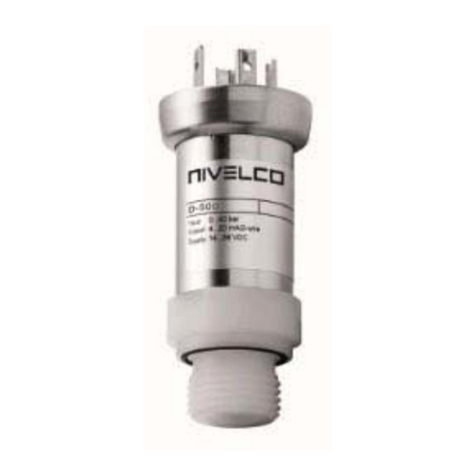
NIVELCO NIPRESS D-500 Series User manual

NIVELCO

NIVELCO NIPRESS D-500 Series User manual

NIVELCO NIPRESS D 9 Series User manual

NIVELCO

NIVELCO NIPRESS D 9 Series User manual

NIVELCO EasyTREK SCD-300 Series Assembly instructions

NIVELCO

NIVELCO EasyTREK SCD-300 Series Assembly instructions

NIVELCO EasyTREK SP-300 Assembly instructions

NIVELCO

NIVELCO EasyTREK SP-300 Assembly instructions

NIVELCO NIPRESS D-300 Series User manual

NIVELCO

NIVELCO NIPRESS D-300 Series User manual

NIVELCO NIPRESS D 3 Series User manual

NIVELCO

NIVELCO NIPRESS D 3 Series User manual

NIVELCO NIVOPRESS NT Series User manual

NIVELCO

NIVELCO NIVOPRESS NT Series User manual

NIVELCO NIVOTRACK M-300 series Assembly instructions

NIVELCO

NIVELCO NIVOTRACK M-300 series Assembly instructions

Popular Transmitter manuals by other brands

Spektrum NX10SE instruction manual

Spektrum

Spektrum NX10SE instruction manual

Metal Samples MS2700E Operator's manual

Metal Samples

Metal Samples MS2700E Operator's manual

Hawk Intelligent 2000-SAN Series instruction manual

Hawk

Hawk Intelligent 2000-SAN Series instruction manual

Regin HTWT10 instructions

Regin

Regin HTWT10 instructions

AFRISO DMU 30 operating manual

AFRISO

AFRISO DMU 30 operating manual

RVR Solar TEX-LCD Series Additional manual

RVR Solar

RVR Solar TEX-LCD Series Additional manual

Xylem MJK pHix Compact V3 manual

Xylem

Xylem MJK pHix Compact V3 manual

Cobalt Digital Inc BlueBox BBG-OE-MK2 Fiber-To-Coax quick start guide

Cobalt Digital Inc

Cobalt Digital Inc BlueBox BBG-OE-MK2 Fiber-To-Coax quick start guide

Canon Wireless File Transmitter WFT-E2 II A instruction manual

Canon

Canon Wireless File Transmitter WFT-E2 II A instruction manual

Philips Bodine WHRCT user manual

Philips

Philips Bodine WHRCT user manual

Teledyne OT-2 operating instructions

Teledyne

Teledyne OT-2 operating instructions

Aerielle i2i-RDS user guide

Aerielle

Aerielle i2i-RDS user guide

Emerson Rosemount 5081-T instruction manual

Emerson

Emerson Rosemount 5081-T instruction manual

AMERITECH AM5 instruction manual

AMERITECH

AMERITECH AM5 instruction manual

Nautel VS300 Operation and maintenance manual

Nautel

Nautel VS300 Operation and maintenance manual

Aplisens AS user manual

Aplisens

Aplisens AS user manual

E+E Elektronik EE360 Operation manual

E+E Elektronik

E+E Elektronik EE360 Operation manual

Sony DWT-P01N operating instructions

Sony

Sony DWT-P01N operating instructions

manuals.online logo
manuals.online logoBrands
  • About & Mission
  • Contact us
  • Privacy Policy
  • Terms and Conditions

Copyright 2025 Manuals.Online. All Rights Reserved.