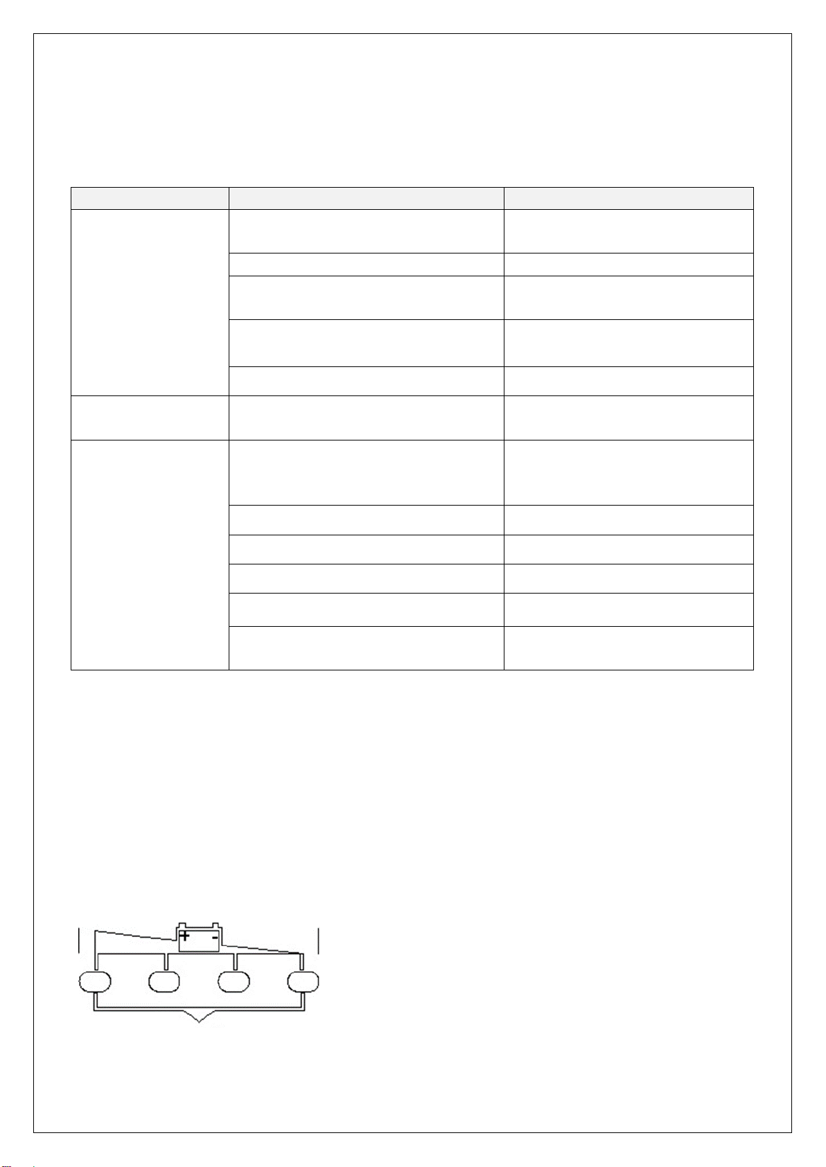
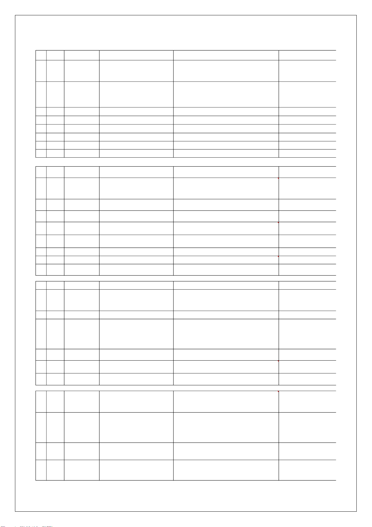
Noblelift PTE15Q User manual

WARNING
Do not use the pallet truck before reading and
understanding these operating instructions.
NOTE:
Please check the designations of your present
type at the last page of this document as well
as on the ID-plate.
Keep for future reference.
Tell:4008-836115
Version 01/2022
Service & Maintenance Manual
Electric Pallet Truck
PTE15Q

TABLE OF CONTENTS
1. REGULAR MAINTENANCE............................................................................................................... 2
a. Maintenance checklist..................................................................................................................... 2
b. Lubrication points............................................................................................................................ 4
c. Check and refill hydraulic oil........................................................................................................... 4
d. Check electrical fuses..................................................................................................................... 5
2. TROUBLE SHOOTING ...................................................................................................................... 6
a. Common trouble shooting............................................................................................................... 6
b. Fault code ....................................................................................................................................... 6
3. WIRING/CIRCUIT DIAGRAM............................................................................................................. 9
a. Electrical circuit diagram................................................................................................................. 9
b. Hydraulic circuit............................................................................................................................. 10
4. MAINTENANCE OF MAIN COMPONENTS.....................................................................................11
a. Battery replacement.......................................................................................................................11
b. Battery and charger .......................................................................................................................11
1. 8A&12A..........................................................................................................................................11
2. Battery introduction....................................................................................................................... 12
c. Outer-appearance parts................................................................................................................ 12
d. Tiller............................................................................................................................................... 14
e. Disassembly of cylinder................................................................................................................ 15
f. Pump disassemble from machine ................................................................................................ 17
g. Disassembly of driving unit........................................................................................................... 18
h. Disassembly of brake.................................................................................................................... 19
i. Driving wheel.................................................................................................................................19
J. Disassembly of emergency button ............................................................................................... 20
K. Disassembly of controller.............................................................................................................. 21
L. Disassembly of contactor.............................................................................................................. 21
M. Disassembly of chassis................................................................................................................. 22
N. Pump motor................................................................................................................................... 23
O. Side roller and adjustment............................................................................................................ 23
5. CURTIS handheld programmed....................................................................................................... 23
6. Handheld Unit with Electric Control of Jiachen................................................................................ 30
a. Function introduction..................................................................................................................... 30
1. Function description...................................................................................................................... 30
2. Features........................................................................................................................................ 30
3. Technical parameters.................................................................................................................... 31
4. Interface pin definition................................................................................................................... 31
5. Button............................................................................................................................................ 32
b. Function description...................................................................................................................... 33
1. Main interface menu......................................................................................................................... 33
2.System Information............................................................................................................................ 34

1
P. Parameter setting.......................................................................................................................... 34
Q. Parameter monitoring ................................................................................................................... 35
R. Fault information........................................................................................................................... 36
S. System Settings............................................................................................................................ 37
T. Mechanical dimensions ................................................................................................................ 38

2
1. REGULAR MAINTENANCE
a.Maintenance checklist
1. Safety button / Belly button
2. Tiller
3. Magnetic lock
4. Discharge indicator and charging indicating LED
5. Emergence button
6. Hydraulic unit cover
7. chassis
8. leg
9. Load roller
10. Battery
11. Apron
12. Driving unit
13. Side roller (option)

3
Maintenance checklist
Interval(Month)
1
3
6
12
Hydraulic
1
Checkthehydrauliccylinder(s),pistonfordamagenoiseandleakage
2
Checkthehydraulicjointsfordamageandleakage
3
Inspectthehydraulicoillevel,refillifnecessary
4
Refillthehydraulic oil(12month or1500workinghours)
5
Checkandadjustfunctionofthepressurevalve(1500kg
/2000kg
+0/+10%)
Mechanical system
6
Inspecttheforksfordeformationandcracks
7
Checkthechassisfordeformationandcracks
8
Checkif allscrewsarefixed
9
Checkthepushrodsfordeformationanddamages
10
Checkthegearboxfornoiseandleakage
11
Inspectthewheelsfordeformationanddamages
12
Inspect
and lubricate the steering bearing
13
Inspectandlubricatethepivotpoints
14
Lubricate the grease nipples
Electrical system
15
Inspecttheelectricwiringfordamage
16
Check the electric connections and terminals
17
Test the Emergency switch function
18
Checktheelectricdrivemotorfornoiseanddamages
19
Test thedisplay
20
Check,ifcorrectfusesareused
21
Test thewarningsignal
22
Check the contactor(s)
23
Checktheframeleakage(insulationtest)
24
Checkfunctionandmechanicalwearoftheaccelerator
25
Checktheelectricalsystemofthedrivemotor
Braking system
26
Checkbrakeperformance,if necessaryreplacethebrakediscoradjusttheairgap
Battery
27
Checkthebatteryvoltage
28
Cleanandgreasetheterminalsandcheckforcorrosionanddamage
29
Checkthebatteryhousingfordamages
Charger
30
Checkthemainpowercablefordamages
31
Check the start-up protection during charging
Function
32
Checkthehornfunction

4
33
Checktheairgapoftheelectromagneticbrake
34
Test the emergency braking
35
Test thereverseandregenerativebraking
36
Testthesafety(belly)buttonfunction
37
Check the steering function
38
Checktheliftingandloweringfunction
39
Checkthetillerarmswitchfunction
General
40
Checkifalldecalsarelegibleandcomplete
41
Inspectthecastors,adjusttheheightor replacetheseifwornout
42
Carry out a test run
b. Lubrication points
Lubricate the marked points according to the maintenance checklist.
The required grease specification is: DIN 51825, standard grease.
c.Check and refill hydraulic oil
It is recommended to use hydraulic oil in connection with average temperature:
Environment
temperature
–5℃~25℃
>25℃
Type
HVLP 32,
DIN 51524
HLP 46,
DIN 51524
Viscosity
28.8-35.2
41.4 - 47
Amount
0.4 L
Lubrication points

5
Waste material like oil, used batteries or other must be probably disposed and recycled according to
the national regulations and if necessary brought to a recycling company.
The oil level height shall be in the not lifted position min. 0.3L to 0.5L. If necessarily add oil at the
filling point.
d. Check electrical fuses
Table 2: Size of the fuses
Rate
FU1
10A
FU01
70A

6
2. TROUBLE SHOOTING
a. Common trouble shooting
Table 3: Trouble shooting
TROUBLE
CAUSE
REPAIR
Load can’t be lifted
Load weight too high
Lift only the max. capacity, mentioned
on the ID-plate
Battery discharged
Charge the battery
Lifting fuse faulty
Check and eventually replace the
lifting fuse
Hydraulic oil level too low
Check and eventually refill hydraulic
oil
Oil leakage
Repair the sealing of the cylinder
Oil leakage from air
breathing
Excessive quantity of oil
Reduce oil quantity
Truck not starts
operating
Battery is charging
Charge the battery completely and
then remove the main power plug
form the electrical socket.
Battery not connected
Connect the battery correctly
Fuse faulty
Check and eventually replace fuses
Low battery
Charge the battery
Emergency switch is activated
Turn the emergency clockwise
Tiller in the operating
Move the tiller firstly to the braking
zone
If the truck has malfunctions and can’t be operated out of the working zone, jack the truck up and go
with a load handler under the truck and safe the truck securely. Then move truck out of the aisle.
b. Fault code
Four power lights flash, and then the first power light flashes, start to count. The forth power light
flashes, start to count again. The fault code is the multiply the first count by ten and then plus the
forth count.

7
Number
Fault code
displayed on
handle
Fault name
Fault description Solution Fault source
1 2
(UpRight_Fault) the interlock switch is closed when upright driving
The interlock switch is closed in the upright driving mode. If the upright
driving switch (tortoise speed switch) is released, the fault has not been
cleared after resetting the interlock:
1. The uprightl drive switch (tortoise speed switch) is stuck, and the handle
shall be replaced“
BM24C10-CAN controller
2 3
Inertlock_Fault
1. The interlock switch is closed in advance before
startup
2. Wrong operation sequenceof direction and
interlock
3. Interlock switch is disconnected first and then
closed during operation
If the interlock is reset, the fault has not been cleared:
1. Check whether the interlock switch harness (J1-9) is short circuited with
3 -;
2. Replace the interlock switch;
BM24C10-CAN controller
3 4
Pedal_Fault
1. Accelerator damaged
2. Handle analog quantity > 4096 or < 0
Accelerator analog out of range
1. Replace the handle BM24C10-CAN controller
4 6
Precharge_Fault The precharge circuit is damaged
Check whether the KSI port (J1-6) is in good contact
If there is no abnormality, replace the controller
BM24C10-CAN controller
5 6
Precharge_Fault Precharge time is too long
Check whether the KSI port (J1-6) is in good contact
If there is no abnormality, replace the controller
BM24C10-CAN controller
6 8
MainOff_Fault
1. The main contactor is stick together or get stuck
2. Main contactor drive failure
replace the controller BM24C10-CAN controller
7 9
MainOn_Fault 1. The main contactor drive loop is open replace the controller BM24C10-CAN controller
810
BrakeOff_Fault
1. Short circuit in brake drive loop
2. Short circuit of brake coil
replace the controller BM24C10-CAN controller
912
BatDisconnect_Fault Poor connection of battery B +, B- circuit
Check whether the power line B + / B - is well connected;
If there is no problem, replace the controller
BM24C10-CAN controller
10 13
BrakeOn_Fault
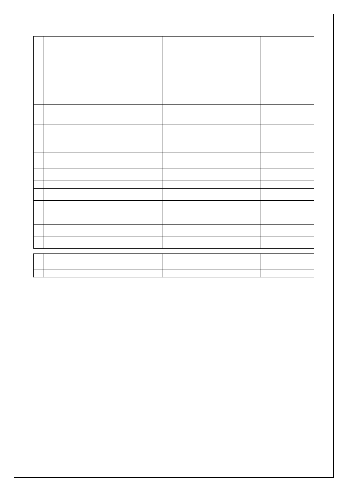
1. Open circuit of brake drive circuit
2. Open circuit of brake coil
1. Check whether the electromagnetic brake harness (J1-1 /J1-2) is well
connected;
2. If the electromagnetic brake is damaged, replace the electromagnetic
brake;
3. Replace the controller;
BM24C10-CAN controller
11 15
Hardware_Fault Controller hardware failure, replace the controller replace the controller BM24C10-CAN controller
12 15
OutRange_15V Internal 15V voltage > 18 volts or < 12 volts replace the controller BM24C10-CAN controller
13 15
M1Short_Fault
1. M1 bridge arm fault and MOSFET damage
2. The motor line is short circuited to the outside
1. Replace the controller
2. Check whether M1 motor line is short circuited with B + / B - / motor
housing, and replace the motor;
BM24C10-CAN controller
14 15
M2Short_Fault
1. M1 bridge arm fault and MOSFET damage
2. The motor line is short circuited to the outside
1. Replace the controller
2. Check whether M2 motor line is short circuited with B + / B - / motor
housing, and replace the motor;
BM24C10-CAN controller
15 19
MotorDisconnect_Fault
1. The motor is not connected
2. Motor M1 and M2 circuits are poorly connected“
1. Check whether the connection between the motor line and the controller
is good;
BM24C10-CAN controller
16 20
OverCurrent_Fault
The controller current is greater than the protection
value
1. Short circuit of motor or motor line;
2. Restart. If the fault still exists, replace the controller
BM24C10-CAN controller
17 22
Controller_Temp_Fault Controller temperature > 100 ℃ or < - 40 ℃
1. Whether the actual temperature of the controller is too high or too low;
2. If the controller temperature is - 40 ℃<T < 100 ℃, replace the
controller
BM24C10-CAN controller
18 26
OverVoltage_Fault Battery voltage < 17 Volts
Battery voltage too high
1. Check whether the battery voltage is higher than 35V
BM24C10-CAN controller
19 28
UnderVoltage_Fault Battery voltage <17 Volts
Battery voltage too low
1. Check whether the B + / B - power line is well connected;
2. If the battery voltage is too low ,charge it;
3. If the battery is damaged, replace the battery;
4. If the voltage is normal and the fault still exists, replace the controller;
BM24C10-CAN controller
20 29
EEprom_Fault EEPROM read / write parameter failure replace the controller BM24C10-CAN controller
21 32
CAN_Fault
1. Check CAN line connection and CAN-BUS
resistance;
2. Check the lithium battery BMS;
1. Check whether the can lines of battery, handle and controller are
connected correctly;
2. Measure whether there is 60 Ω terminal resistance on CAN-BUS;
3. If the lithium battery BMS is damaged, replace the lithium battery;
4. If the handle communication module is damaged, replace the handle;
5. If the controller communication module is damaged, replace the
controller
BM24C10-CAN controller
22 33
LiftOff_Fault
1. The relay drive circuit is short circuited.
2. Relay coil short circuit
replace the controller BM24C10-CAN controller
23 33
LiftOn_Fault
1. Open circuit of relay drive circuit.
2. Open circuit of relay coil
1. Check whether the lifting relay harness (J1-5 / 3 -) is well connected
2. If the lifting contactor is damaged, replace the lifting contactor;
3. Replace the controller;
BM24C10-CAN controller
24 34
LowerOff_Fault
1. The relay drive circuit is short circuited.
2. Relay coil short circuit
replace the controller BM24C10-CAN controller
25 34
LowerOn_Fault
1. Open circuit of relay drive circuit.
2. Open circuit of relay coil
1. Check whether the descending solenoid valve harness (J1-7 / 3 -) is well
connected
2. If the lowering solenoid valve is damaged, replace the lowering solenoid
valve;
3. Replace the controller;
BM24C10-CAN controller
26 37
EMR_Fault
1. Before the key switch is powered on, the
emergency reverse switch is closed
2. Emergency reverse logic failure
The emergency reverse is triggered normally and an emergency reverse
fault is reported. If the fault is not cleared after resetting the interlock:
1. Check whether the emergency reverse switch harness (J1-13) is
connected well;
2. The emergency reverse switch is stuck;
3. Whether the type parameter setting of emergency reverse switch is
correct;
BM24C10-CAN controller
27 38
BMSTimeout_Fault Failed to connect with BMS 7S after power on
1. Check whether the CAN line between the battery and the controller is
well connected;
2. Check whether the controller software is correct;
3. Check whether the battery BMS software is correct;
BM24C10-CAN controller
28 80
The tortoise speed button detects closure before
power on.
1. Whether the handle speed button is pressed and stuck;
2. Check whether the microswitch under the turtle speed button is
normally closed, and replace the microswitch assembly;
3. Replace the upper cover of the handle;
Handle

8
29 81
Lift fault
The lifting button is detected to be pressed before
power on.
1. Whether the handle lifting button is pressed and stuck;
2. Whether the microswitch under the lifting button is normally closed, and
replace the microswitch assembly;
3. Replace the upper cover of the handle;
Handle
30 82
Lower fault
The descent button is detected to be pressed before
power on.
1. Whether the handle lowering button is pressed and stuck;
2. Whether the microswitch under the lowering button is normally closed,
and replace the microswitch assembly;
3. Replace the upper cover of the handle;
Handle
31 83
BMS Communication
Outage
1. Lithium battery BMS is damaged.
2. The communication line from the lithium battery
to the handle is broken.
3. The communication module of the handle is
damaged.
1. Replace the lithium battery;
2. Replace the handle harness, main controller harness and main power
harness;
3. Replace the handle;
Handle
32 84
throttle_FAULT
Before entering the password, the throttle is not in
the middle position, and the throttle needs to be
reset to remove the fault.
1. If the throttle is in the neutral position and the power supply is restarted,
whether the fault is removed;
2. Replace throttle components;
Handle
33 85
Controller
Communication Outage
1. The controller BMS is damaged.
2. The communication line from the controller to the
handle is broken.
3. The communication module of the handle is
damaged.
1. Replace the controller;
2. Replace handle harness and main controller harness;
3. Replace the handle;
Handle
34 86
LowBDI
The battery level is lower than the low battery
threshold setting
The current power is lower than the low power setting (15%):
1. The battery is low and needs to be charged;
2. Check whether the handle is correct and replace the handle (when the
lead-acid battery is used, the handle needs to calculate the power);
BM24C10-CAN controller
35 87
Lift system failure
The output of the pump station operates
continuously, and the lifting system fails, which may
be the failure of the lift microswitch
1. If the limit switch cannot be triggered, adjust the electric control board;
2. The normally closed contact of limit switch is short circuited;
3. The lifting contactor is stuck;
Handle
36 90
Over Voltage
1. The charger may be overcharged.
2. There is a problem with the battery BMS.
3. When the vehicle goes downhill for a long time,
the feedback current is caused by charging.
1. The charger is overcharged and the cut-off voltage of the charger is too
high;
2. Replace the battery;
3. Caused by vehicle downhill for a long time;
lithium battery
37 91
Over Discharge
1. Lithium battery is not used for a long time,
resulting in low battery power.
2. Overuse.
Regularly recharge the battery;
lithium battery
38 92
Communication Outage
电池通讯超时故障
Battery communication timeout, communication
timeout with controller
Replace the battery lithium battery
39 93
Under Voltage
1. Long term storage, no timely charging.
2. The internal cell of the battery is damaged,
resulting in failure to charge.
1. Regularly recharge the battery;
2. Replace the battery; lithium battery
40 94
Over Current
1. The device can not work according to the program
originally set by the controller.
2. After the controller is replaced, the parameters do
not match.
3. Lithium batteries have problems in current
detection.
1. Replace the controller;
2. Modification of controller parameters;
3. Replace the battery;
lithium battery
41 95
Over Temperature
Protect
The battery temperature is too high, and the use or
transportation environment causes serious high
temperature inside the battery.
1. The internal temperature of the battery is too high;
2. If the internal temperature sensor of the battery fails, replace the battery;
lithium battery
42 96
Temperature Protect
The battery temperature is too high and the use or
transportation environment causes high
temperature inside the battery.
1. The internal temperature of the battery is too high;
2. If the internal temperature sensor of the battery fails, replace the battery;
lithium battery
43 reserve
Motor_Temp_Fault reserve BM24C10-CAN controller
44 reserve
PumpSRO_Fault The lifting switch is closed before opening BM24C10-CAN controller
45 reserve
System task failure reserve BM24C10-CAN controller
PTE15Q Fault code

9
3. WIRING/CIRCUIT DIAGRAM
a. Electrical circuit diagram
PTE15Q
Table 4: Description of electrical diagram
Code.
Item
Code
Item
GB
Battery
B
CAN tiller
Et
Controller
SA
Proximity switch
Mp
Pump motor
Mt
Traction motor
KMp
Pump contactor
YB
Electromagnetic brake
SM
Emergency button
FU1
10A fuse
YV
Electromagnetic valve
FU01
70A fuse

10
SU
Micro switch
b.Hydraulic circuit
Table 5: Hydraulic oil inspection
Degree of purity
Smell
Status
Result
Clear and same color as before
Good
Good
Can be used
Transparent
Good
Mixed with other oil
Can be used if viscosity is fine
Milky
Good
Mixed with water and air
Separate water or replace
hydraulic oil
Brown
Bad
Oxidation
Replace hydraulic oil
Transparent but with particles
Good
Mixed with other particles
Can be used after filtering
Lifting cylinder
Lowering valve
Pressure control valve
Hydraulic power unit
Oil tank
Throttle valve

11
4. MAINTENANCE OF MAIN COMPONENTS
a. Battery replacement
Unplug the plug, flip the switch outward to remove the battery.
b.Battery and charger
1.8A&12A

12
2.Battery introduction
c.Outer-appearance parts
1.Remove the Electronically controlled cover and unscrew 4 screws to remove the cover.

13
2.Driving wheel cover
There are 2 fixed screws in the small cover.
There are 4 fixed screws in the small cover.

14
d. Tiller
1.Remove the two fixed screws to open the rear cover. Remove the internal wiring harness and remove
the handle.
2.Disassembly of air spring
Remove the screw with
5mmAllen wrench.
Remove the circlip
with circlip plier.
Remove the axle.
Remove the circlip and
axle.

15
3.Assembly of air spring
Put the air spring into
the tiller arm.
Insert the axle.
Make hole of axle and
hole of screw on the
same level with Allen
wrench.
Support the air spring
with flat metal tool to fix
the screw.
e. Disassembly of cylinder
Remove the screw with
5mmAllen wrench.
Put a wooden block
under the chassis.
Power on the truck,
activate the lowering
button and apply some
force on top of the
cylinder to retract the
piston rod.
Turn over the
cylinder.

16
For PTE15Q, there is a O ring on the valve. Please
keep it.
Pull out the protective
cover from top.
Disconnect the cylinder
from pump with 5mm
Allen wrench. During
assembly, it’s required to
apply thread locker with
1243 model.

17
f. Pump disassemble from machine
Remove the left screw
with 5mmAllen wrench.
Remove the right screw
with 5mmAllen wrench.
Remove the top screw
with 5mmAllen wrench.
Put a wooden block
under the chassis.
Power on the truck,
activate the lowering
button and apply some
force on top of the
cylinder to retreat the
piston rod
Turn over the cylinder.
Disconnect the cylinder
from pump with Allen
wrench.
After disconnection,
there is an O ring on
the valve.
Loosen the clamp with the screwdriver.
Disconnect the oil tank from pump, during
assembly ensure O ring is inside the groove.
Loosen the screw with 10mm Allen wrench.
Tighten the screw with 3mmAllen wrench
to increase the pressure or loosen the
screw to release the pressure.

18
g.Disassembly of driving unit
Remove the screw with 6mm
Allen wrench.
Remove 4 screws with 6mm
Allen wrench. It’s required to
apply thread locker with 1243
model.
Remove the driving unit from
the chassis.
Pad the hole in the middle
with an iron sheet or other
hard object and remove the
bearing.
First remove the bearing, then
remove 4 screws with 6mm
Allen wrench to take out the
flange. It’s required to apply
thread locker with 1243 model.
Remove the screw with 5mm
Allen wrench to take out the
plastic cover.
Other manuals for PTE15Q
1
Table of contents
Other Noblelift Truck manuals

Noblelift
Noblelift FE3P16-35 N User manual

Noblelift
Noblelift PTE15Q User manual

Noblelift
Noblelift EPT15 User manual

Noblelift
Noblelift RT16Li User manual

Noblelift
Noblelift PTE15/20Q-B User manual

Noblelift
Noblelift HPT20S User manual

Noblelift
Noblelift RT16P User manual

Noblelift
Noblelift PTE15N SC User manual

Noblelift
Noblelift PT20H manual

Noblelift
Noblelift PTE15Q-A User manual