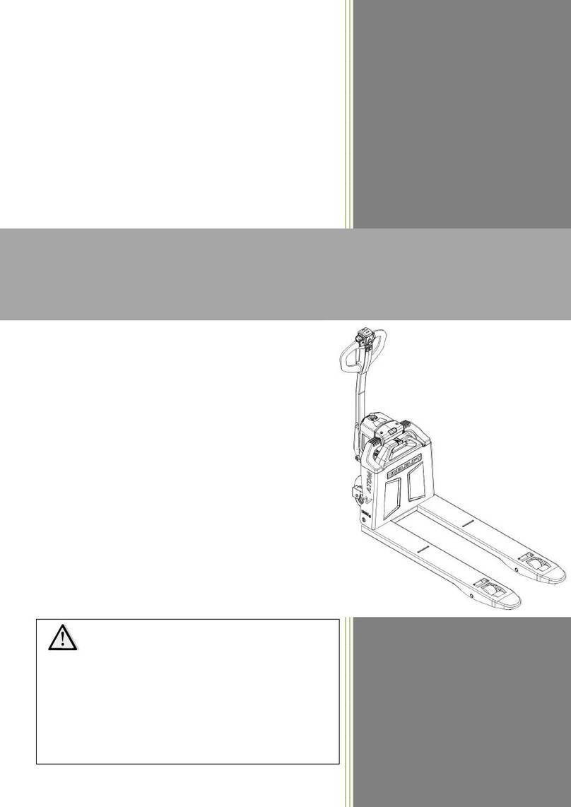
Noblelift N Series Manual

FE3R08-12-SMS-001
Warning
Operators should read and understand
this manual and all warning labels on
the forklift before using the forklift!
Keep the manual for future reference!
Operation & Maintenance Manual
FE3R08-12 N SERIES
Battery Counterbalanced Forklift Truck
NOBLELIFT INTELLIGENT EQUIPMENT CO.,LTD.

1
Table of Contents
Introduction…………………………………………………………………………………………… 4
Chapter 1 Precautions of using forklift…………………………………………………………… 5
. Forklift transportationⅠ...................................................................................................... 5
. Forklift storageⅡ................................................................................................................ 5
. PreⅢ-use preparation........................................................................................................ 5
. Operation of the forkliftⅣ................................................................................................... 5
. Charging of accumulator cellsⅤ........................................................................................ 6
Chapter 2 Structure and main performance parameters of the forklift………………………… 7
. Overall DⅠimension and Technical Parameters of the forklift .......................................... 7
1. Overall dimension......................................................................................................... 7
2 Technical Parameters .................................................................................................... 8
. Structure, principle and adjustment of the main componentsⅡ........................................ 9
1. Steering drive axle........................................................................................................ 9
1.1 Overview ................................................................................................................... 9
1.2 Failure Analysis......................................................................................................... 11
2. Braking system ............................................................................................................. 11
2.1 Overview ................................................................................................................... 11
2.2 Brake pedal............................................................................................................... 11
2.3. Brake master cylinder .............................................................................................. 12
2.4. Brake........................................................................................................................ 13
2.5 Technical points for brake disassembly and adjustment .......................................... 15
2.6 Adjustment of brake pedal ...................................................................................... 18
2.7 Troubleshooting and Failure Analysis Failure analysis ............................................ 19
2.8. Care and maintenance ............................................................................................ 20
3 Steering system .......................................................................................................... 20
4 Electrical system............................................................................................................ 20
4.1 Overview ................................................................................................................. 20
4.2 The characteristics of the electronic system ............................................................ 20
4.3 Main functions and settings……………………………………………………………… 20
4.4 Curtis controller fault................................................................................................. 23
5.Accumulator…………………………………………………………………………………… 31
5.1 Accumulator safety precautions………………………………………………………… 31
5.2 Accumulator use precautions…………………………………………………………… 32
5.3 Charging of the accumulator……………………………………………………………… 33
5.4 Installation and replacement of the accumulator………………………………… 35
6.Hydraulic system……………………………………………………………………………… 35
6.1 Overview…………………………………………………………………………………… 35
6.2 Oil pump…………………………………………………………………………………… 35
6.3 Multi-way valve…………………………………………………………………………… 35
6.4 Lifting cylinder and the lifting chain……………………………………………………… 37

2
6.5 Governor valve……………………………………………………………………… 38
6.6 Tilt cylinder………………………………………………………………………………… 39
6.7 Maintenance and adjustment…………………………………………………………… 40
6.8 Failure analysis…………………………………………………………………………… 42
7.Lifting system………………………………………………………………………………… 44
7.1 Overview…………………………………………………………………………………… 44
7.2 Outer and inner main frame……………………………………………………………… 44
7.3 Fork frame………………………………………………………………………………… 45
7.4 Roller position………………………………………………………………………… 46
7.5 Maintenance and adjustment…………………………………………………………… 46
7.6 Installation of accessories………………………………………………………………… 48
8.Removal and installation…………………………………………………………………… 48
8.1 Precautions……………………………………………………………………………… 48
8.2 Lifting points of the detached parts…………………………………………………… 48
Chapter 3 0peration, use and safety of the forklift………………………………………………… 50
.ⅠTransportation and testing the forklift ............................................................................. 50
1 Lifting ........................................................................................................................ 50
2 Transporttation ........................................................................................................... 50
3 Use of a new forklift .................................................................................................. 51
4 The relationship between forklift stability and load .................................................... 51
5 Load centre and load curve........................................................................................... 51
6 Forklift stability .......................................................................................................... 52
7 Adatp a new forlift .......................................................................................................... 52
.ⅡDriving and operation................................................................................................... 52
1. A brief introduction of Console...................................................................................... 52
2 Safety features of the forklift.......................................................................................... 52
3 Forklift driving ................................................................................................................ 53
4 Loading and unloading of the goods………………………………… …………………… 54
. About safetyⅢ.................................................................................................................... 55
1. Site and working environment of the forklift ................................................................. 55
2. Safety rules................................................................................................................... 56
3 Transportation of the forklift ........................................................................................... 66
4 How to avoid rollover and how to protect yourself ........................................................ 66
5 Safety issues during maintenance and protection ........................................................ 68
6 Safety during use of the accumulator............................................................................ 69
7 Signs .............................................................................................................................. 71
Chapter IV Maintenance and repairing of the forklift ............................................................... 72
. Check before operationⅠ.................................................................................................. 72
.ⅡChecking after operation ................................................................................................ 72
. Clean theⅢforklift.............................................................................................................. 73
1. Clean the forklift surface............................................................................................... 74
2. Clean the chain............................................................................................................. 74

3
3 .Clean the electric system ............................................................................................. 74
4 . After the cleaning ......................................................................................................... 74
. Regular maintenanceⅣ..................................................................................................... 74
1. Replace critical safety components periodically........................................................... 74
2. List of forklift oil............................................................................................................. 75
3.Maintenance list 75
.ⅤRepairing of the forklift..................................................................................................... 77
1. Failure diagnosis… ………………………………………………………………………… 77
2. The preparation work before repairing ......................................................................... 78
3.Check the hydraulic oil……………………………………………………………………… 78
4. Check the volume of the brake fluid………………………………………………………… 78
5.Aftermaintenance, the preparatory work before using………………………………… 78
Storage of the forkliftⅥ………………………………………………………………………… 79
1.Operations before storage…………………………………………………………………… 79
2.Measures during storage…………………………………………………………………… 79
3.Re-test the forklift……………………………………………………………………………… 79

4
Introduction
This manual briefly describes the technical parameters of the counterbalanced accumulator
forklift made by our company, and the structure of its main components, working principle and
requirements on operation and maintenance. Please read this manual carefully before operation,
so as to achieve proper driving and maintenance, and to ensure safe and effective material
handling. Meanwhile, this manual aims to guide operators to use the forklift in an appropriate way
and to maximize its performance! We hope that operators and equipment managers could read it
carefully before use! Please strictly observe the provisions and cautions stipulated in this manual
and operate the forklift with caution and care, so that the forklift can be maintained in its best
status and optimal performance can be ensured. When you lease or transfer your forklift, always
keep this manual with it.
For highlighting purpose, the following icons are used in this manual:
1. ----refers to a potential danger; if not avoided, it may cause serious human injury, vehicle
damage or fire.
2. ----refers to a potential danger; if not avoided,it may cause minor human injury, or local
damage to the vehicle.。
3. ----Refers to general cuations and instructions during use.
Most parts of the product are made from recyclable steel. The recycling and disposal of
cast-offs resulted during use, maintenance, cleaning and disassembling of the product has to
comply with local regulations without pollution to the environment. The recycling and disposal of
the cast-offs should only be operated by specialised personnel in the designated area. The
cast-offs, such as hydraulic oil, batteries and electronic units, if improperly disposed, may be
hazardous to the environment and human health.
Special Declaration:
1)This product is strictly prohibited for potentially explosive hazardous environments.
2)The Noise level of the normal use of this product is compliant with international
standards EN 12,053.
3)The vibration level of the normal use of the product is compliant with international
standards EN13059.
4)The normal use of the product's environmental requirements as follows: no more than
2000 meters above sea level and the temperature range of 5 ° C—+40 ° c, humidity should
no more than 90%.The wind speed is not more than 5m/s.
If you need to use in the freezer for a long time, Or in special environmen,it is needed
to install special attachments. Please contact our technical staff.
5)Product recall serive is available when serial faulties occur.
Due to continuous product improvement, Noblelift reserves the right to make changes in
product designs and specifications without prior notice. For the latest product parameters, please
feel free to contact us. All parameters provided herein are as of the publication date of the
Instruction Manual.

5
Chapter 1 Precautions of using forklift
Forklift drivers and managers must remember the principle of "safety first", and carefully read
this maintenance manual. Operators shall be in strict accordance with this manual to ensure safe
and normal operation.
. Forklift transportationⅠ
The following shall be noted when transporting forklift by container or trucks:
(1) Apply the parking brake;
(2) Fix the main frame and counterweight with steel wires, and use pads to wedge the
corresponding positions at the front and rear tires;
(3) Start lifting from the positions indicated by the "Craning Label" on the forklift.
ⅡForklift storage
(1) Reduce the main frame to the lowest position;
(2) Turn off the electric lock, place the lever rod to the "Nertral" position and unplug the power
cord;
(3) Tighten the hand brake;
(4) Use pads to wedge the front and rear tires ;
(5) If the forklift is to be left unused for a long time, its wheels should be elevated. The
accumulator should be recharged once a month.
PreⅢ-use preparation
(1) Check if all instruments are normal;
(2) Check the tire pressure;
(3) Check the condition of the levers and pedals;
(4) Check if the accumulator voltage is within the working scope, and if the specific gracity of
the electrolyte and the height level of the liquid are appropriate;
(5) Check if the connectors and plug contacts of the electrical system are reliable;
(6) Check for leakage of the hydraulic fluid, electrolyte and brake fluid;
(7) Check the tightness of major fasteners;
(8) Check if the lighting and signal lamps are normal;
(9) Release the parking brake;
(10) Conduct test actions such as lifting and lowering the main frame, tilting forwards and
backwards, steering and braking;
(11) Contamination level of hydraulic oil shall not be greater than 12.
Ⅳ. Operation of the forklift
(1) Only trained and licensed drivers can drive the forklift;
(2) Operators shall wear security shoes, hats, clothing and gloves for protection purpose;
(3) Operators should note the performance and working conditions of mechanical, hydraulic,
electrical and MOSFET governor;
(4) Power on by switching on the key switch, choose the right position of direction switch, and
then rotate the steering wheel to see if the forklift can steer.
If ok, slowly depress the speed pedal and maintain an appropriate speed;
(5) Observe the voltage meter, if the voltage indicated by the voltage meter is below 41V
during working, immediately stop operation, and recharge the accumulator or replace with another
fully charged accumulator;
(6) Weight of loads handled should not exceed the specified value and fork spacing and
location should be appropriate. The fork should be fully inserted below all the goods, which shall
be uniformly distributed on the fork. Uneven loading shall be avoided;
(7) If the distance between loads‘ center of gravity and the fork arm is no more than 500mm, the
maximum load shall be the rated capacity. If the distance between loads‘ center of gravity and the fork
arm is more than 500mm, the maximum load shall be less than the rated capacity;
(8) When carrying loads, the main frame should tit backwards to the maximum extent and the
fork arm should be in contact with the goods. Raise the fork to about 200mm away from the
ground before driving;
(9) Standing under the fork and on the lifting fork are forbidden;
6
(10) The initial velocity should not be too fast when lifting and lowering goods;
(11) Never operate the forklift and accessories at places other than the driver's seat;
(12) When the main frame is moving forwards and backwards to the maximum extent, or
when the fork is lifted to its maximum height, the operator must rapidly set the lever to the neutral
position;
(13) When the main frame is lifting, driving or turning of the forklift is not allowed;
(14) When driving the forklift, drivers should pay attention to pedestrians, road obstacles and
potholes, and also note the gap above the forklift;
(15) Drivers should be very careful when driving on ramps. When driving on a ramp with slope
gradient more than one-tenth, do move forward for up-hilling and backward for down-hilling.
Never perform steering during up-hilling ad down-hilling process. And avoid loading and unloading
when the forklift is down-hilling;
(16) Slow down when steering on wet or slippery road surfaces; be very careful and drive
slowly when driving on docks or temporary boards;
(17) For forklifts with lifting height greater than 3 meters, users shall be careful to guard
against falling down of the goods overhead and take protective measures if necessary;
(18) Do not carry unfixed or loosely stacked goods and be careful when handling goods with
large size;
(19) When driving the forklift with load, emergency braking should be avoided;
(20) Before leaving the forklift, lower the fork down to the ground, set the lever at neutral
position and disconnect power. In case of parking on a ramp,
apply the parking brake. Use wedge pads to fix the wheels if you need to park for a long time;
(21) The safety valve pressures of multiple unit valve and steering device have been tuned up
before leaving the factory. During use, users
shall not adjust it, because excessive pressure may cause damage to the entire hydraulic system
or its components ,and the motor;
(22) When moving with no load, forklift with accessories shall be operated in a way as if
carrying a load.
. Charging of accumulator cellsⅤ
(1) When charging the accumulator cells for the first time and further charging, users should
be in strict compliance with the instructions;
(2) When operating the forklift, if the accumulator voltage decreases to 41V, or that of its
single cell drops below l.7V , or the instrument alarms, users shall immediately stop using the
forklift and replace the accumulator or recharge it before further use;
(3) Check the specific gravity, liquid level and temperature of the electrolyte from time to time
during the charging process;
(4) Forklift must be recharged as soon as possible after use. Never leave the forklift
uncharged longer than 24 hours. When charging, pay attention to prevent
insufficient charging and over-charging, so as not to damage the battery;
(5) Users should conduct balanced recharging to the forklift in normal use once a month, so
as to adjust the proportion among the accumulator units.
Please refer to the relevant sections of this Mannual for detailed charging and maintenance
methods.

7
Chapter 2 Structure and main parameters of the forklift
. Overall size and performance parameters of the forkliftⅠ
1. Overall dimensions (as shown in Figure 1-1 )
Figure 1-1 Overall dimension

8
2. Technical parameters (Table 1-1)
Characteriscis
Mode FE3R08 FE3R10 FE3R12
Drive mode: Electric Electric Electric
Operation mode:Manual, walking, stand-up
driving, Sit-down driving, picking Sit-down Sit-down Sit-down
Rated loading capacity Q(Kg) 800 1000 1200
Load centre distance C(mm) 500 500 500
Front overhang distance x(mm) 265 265 265
Wheelbase y (mm) 841/923 951/1033 991/1073
weigh
t
Weight with accumulator Kg 1800 1910 2080
Axle load with full load, front/rear Kg 2300/300 2460/350 2880/400
Axle load with no load, front/rear Kg 770/1020 850/1060 910/1170
Wheel,body
Tires:solid rubber,super- elastic, pneumatic,
polyurethane tires
Solid rubber/
polyurethan
Solid rubber/
polyurethan
Solid rubber/
polyurethan
Specification of Front wheel 13×4½×8 13×4½×8 13×4½×8
Specification of rear wheel b10(mm) φ250×82 φ250×82 φ343×140
Front wheelbase b11(mm) 765 765 765
Basic size
Tilt angle of main frame, forward/backward
α/β(°) 3°/5° 3°/5° 3°/5°
Height of main frame when retracted
h
1(mm) 1965 1965 1965
Free lifting height h2(mm) 95 95 95
Lifting height h3(mm) 3000 3000 3000
Height of main frame when stretched
h
4(mm) 3865 3865 3865
Height of overhead guard h6(mm) 1975 1975 1975
Seat height h7(mm) 980 980 980
Traction pin height h10(mm) 540 540 540
Total length l1(mm) 2290 2400 2460
Length of forklift body (Fork surface)
l2( mm ) 1370 1480 1545
Tota l wid th b1(mm) 880 880 880
Fork dimension s/e/l(mm) 35/100/920 35/100/920 35/100/920
Distance from main frame to ground m2(mm) 80 80 80
Distance from wheel base centre to ground
m
2(mm) 90 90 90
Turning radius Wa(mm) 1160 1320 1350
Performance
p
arameters
Driving speed, full load/no load km/h 8/9 7.5/9 7.0/9
Lifting speed,full load/no load m/s 0.17/0.28 0.16/0.22 0.15/0.22
Lowering speed full load/no loadm/s 0.23/0.22 0.16/0.20 0.17/0.20
Maximum traction, full load/no load S25
min % 3320/3530 3320/3600 3420/3640
Climbing ability, full load/no load S25 min
%
6/10 6/10 6/10

9
motor
Drive motor power S260min Kw 2.5 2.5 3
Lifting motor power S3 15% Kw 3 3 3
Accumulator voltage/capacity K5V/Ah 24/280 24/420 24/420
Accumulator weight kg 280 392 392
others
Drive control type AC AC AC
Working pressure of accessories Pa 115 135 155
Oil volume of accessories l / min 16 16 16
Noise level at driver's ear according to EN 12
053 EN 12 053 decible 70 70 70
.Structure, principle and adjustment of the forklift’s main componentsⅡ
1. Steering drive axle
1.1 Overview
The steering drive axle of forklift is composed of reduction gearbox assembly,drive motor and
slewing bearing. Driving gear of decelerator is connected directly with the travel motor, so the
driving speed of forklift increases with the increase of motor speed and the driving direction can be
changed by changing the direction of motor rotation.

10
1. steering motor 2. screw 3. spring washer 4. washer
5. bolt 6. heel 7. spring washer 8. washer
9.bolt 10. proximity switch 11. Steering pinion 12. washer
13. Electromagnetic
brake (optional) 14. motor 15. coder 16. bolt
17. spring washer 18. washer 19. Gearbox mounting
board 20. gear-box
21. back wheel 22. boss bolt
Figure 2-1 Steering drive axle

11
The drive steering axle has a characteritics of compact structure, reliable performance,
smooth transmission and low noise. Axle shell is made of steel materials, which provides strong
rigidity and high load capacity. See Table 2-1 for the main technical parameters.
Table 2-1 main performance parameters
Model FE3R08-10 FE3R12
Motor Power kw 2.5 3.0
Motor rated speed r/min 2500 2500
Battery voltage V 24 24
Gear Ratio i 18.98 22.32
Maximum wheel load kg 1100 1400
Wheel diameter mm 254 343
1.2 Failure Analysis
Table 2-2 Failure Diagnosis and Correction
Failures Possible causes Correction methods
High
vibration
Looseness of fastening bolts at the installation
and connection points Tighten the bolts
Excessive
oil
temperature
Deterioration of gear oil Replace
Abnormal oil level Add or reduce oil
Jamming of moving parts Adjustment
Oil leakage
Looseness of bolts at the combining surfaces Tighten the bolts
Damaged seals Replace
Noise Damaged rotary gear Replace
Damaged bearing Replace
2. Braking system
2.1 Overview
The braking system consists of the brake pedal, brake master cylinder and wheel brakes. The
two wheel brakes in the front are hydraulic internal expansion brakes.
2.2 Brake pedal
The structure of brake pedal is shown in Figure 2-2. The pedal would transfer the pedal force
into brake oil pressure through the push rod on the brake master cylinder.

12
1 Screw 2. Spring washer 3. Fixed plate 4.Axle
5. Bearing 6 Socket hexagonal screw. 7. Spacing bolt 8. Foot brake bracket
9. Brake pedal 10. Return spring 11.Brake pump assembly
Figure 2-2 Brake pedal assembly
2.3 Brake master cylinder (Figure 2-3)
The master cylinder includes a valve seat, a check valve, a return spring, the main cup, piston
and auxiliary cup. Stop washer and stop steel wire are used to fix the ends of the cylinder and
rubber dust cover is applied to protect its external surface. Master cylinder piston works by
depressed the brake pedal to touch the push rod. When the brake pedal is depressed, the push
rod will push the piston forward, and the brake fluid in the cylinder will flow back to the storage tank
through the oil return hole until the main cup block the oil return hole. When the main cup block the
oil return hole, the brake fluid in front cavity of the master cylinder is compressed and the check
valve is opened. The fluid will flow to the wheel cylinder through the brake pipelines. Thus, each
wheel cylinder piston will protrude and the friction disk of the brake shoe will contact the brake
drum to achieve slowing down or braking. At this point, the back cavity of piston will be filled with
brake fluid from the oil return hole and the oil inlet. When the brake pedal is released, the piston
will be pressed backwards by the return spring, and at the same time the brake fluid in each brake
cylinder is also compressed by the return spring of the brake shoe, so that the brake fluid will flow
back to the master cylinder (front cavity of the piston ) through the check valve. Then the piston
will return to its normal position, while the brake fluid in the master cylinder flows back to the
storage tank through the oil returning hole. The pressure of the check valve will be adjusted to be
in certain proportional of the remaining pressures in the brake pipeline and the brake cylinder, so
that the cylinder cup will be correctly placed to prevent oil spilling and to eliminate air resistance
that may occur during emergency brake.

13
Figure 2-3 Brake Master Cylinder
2.4 Brake
The brake is a dual-shoe brake installed on both sides of the drive axle. The brake consists of
two groups of brake shoes, brake cylinders and regulators. One end of the brake shoe
contacts the fixed pin and the other end contacts the regulating device. The return spring and the
compression spring bar hold the parking brake. In addition, the parking brake mechanism and
automatic regulating device are also assembled onto the brake. See figure 2-4
1. Left plate
assembly
2. Brake crow
assembly
3. Brake
Cylinder
4.
Self-adjusting
spring
5. Return
spring
6. Handbrake
self-adjusting
body
7. Handbrake
return spring
8. Spring
compression
9.
compression
bar
10. Tension
spring
11. Spacing
bar
12. Connection
rod dust cover
Figure 2-4 Brake
(1) Brake action
Brake cylinder exerts the same force to the main brake shoe and auxiliary brake shoe to
suppress the brake drum, until the upper end of auxiliary brake shoe contacts against the fixed pin.
Then the brake shoe will move towards the rotation direction of the brake drum. After contact
against the fixed pin, the friction between friction disk and brake drum will increase. The main
brake shoe will exert a pressure larger than the brake cylinder pressure on the auxiliary brake
shoe, resulting in a large braking force. See Figure 2-10
When moving backwards, the brake action is in reverse to that of moving forwards. See
Figure 2-6
1.Locking nut 7.Piston
2.Pushing rod 8.Main cup
3.Dust cover 9.Spring
4.Stop steel wire 10.check valve
5.Stop washer 11.Valve seat
6.Auxiliary cup 12.Pump body

14
Figure 2-5 Action when moving forwards Figure 2-6 Action when moving backwards
(2)Parkingbrake
Mounted in the wheel brake, the parking brake consists of the lever and push lever. The lever
is mounted on side of the main brake shoe by a pin,
and the pulling action spread through the push lever to the auxiliary brake shoe. See figure 2-7
(3) Clearance self-adjusting mechanism
The clearance self-adjusting mechanism can maintain appropriate clearance between the
friction disk and the brake drum. See Figure 2-8 for its structure. Clearance self-adjusting
mechanism works only when the forklift is moving in reverse.
Figure 2-7 Parking brake Figure 2-8Clearance self-adjusting mechanism
(4) Action of the automatic clearance adjusting mechanism
If braking during reversing of the forklift, the auxiliary and main brake shoes contact with each
other and rotate together, so that the lever will rotate rightwards around A point as shown in Figure
2-8, and B point is then elevated. After the brake is released, the lever will rotate leftwards by the
spring force to lower B point. When the clearance between brake hub and friction disk is enlarged,
the vertical distance of B point’s rotation will increase. The regulator will be toggled for one more
tooth and the regulating lever lengthens (see Figure 2-9), so that the clearance shrinks. Clearance
adjustment range falls within 0.40mm ~ 0.45mm.
1. Pin 2. lever 3. Driving brake
shoe
1.Regulating
mechanism
2.
Spring
3. Cable
4. Driven
brake shoe
5.
Support
rod
4. Guide
groove
5. lever
Driving brake shoe
Driven brake shoe
Driving brake shoe Driven brake shoe

15
Figure2-9Clearance
self-adjusting mechanism
2.5 Technical points for brake disassembly and adjustment
Disassembly, assembly and adjustment of the brake and adjustment of brake pedal when the
wheel and wheel hub is removed.
2.5.1 Disassembly of the brake
(1) Remove the support pin, regulating bar, regulating device and spring on the auxiliary
brake shoe. See figure 2-11
(2) Remove the return spring on the shoe. See figure 2-12
Figure2-11 Figure2-12
(3) Remove the fixing spring on the main brake shoe. See figure 2-13
(4) Remove the main and auxiliary brake shoes. And also remove the regulator and the
regulator spring. See figure 2-14
Figure2-13 Figure2-14
(5) Remove the brake pipe from the brake cylinder. Then remove the mounting bolt of the

16
brake cylinder, and remove the brake cylinder from the brake backing plate. See figure 2-15
6) Remove the E-shaped retaining ring used for fixing the brake cable on the brake backing
plate. Then remove the mounting bolt on the brake backing plate and dismount the brake backing
plate from the drive axle. See figure 2-16
Figure2-15 Figure2-16
(7) Disassemle the brake cylinder: Remove the dust-proof ring. Press on one end of the
piston to push out the other end and then press down the headed out end of piston with fingers.
See figure 2-17
Figure 2-17
2.5.2 Check of the brake
Inspect the parts and then repair or replace damaged ones.
(1) Check the surface of the brake cylinder and peripheral surface of the piston for rust; then
measure the clearance between the piston and the brake cylinder.
Standard size: 0.03mm-0.10mm; Maximum size: 0.15mm
(2) Conduct visual inspection of the piston cup for damage and deformation. Replace the cup
if there is any abnormality.
(3) Measure the free length of brake cylinder spring. Replace it if it exceeds the baseline.
(4) Measure the thickness of friction disk. Replace it if the wear degree exceeds limit. Figure
2-23 Standard thickness: 8.0mm; Minimum thickness: 2.0mm
(5) Conduct visual inspection on the inner surface of brake drum for damage and uneven
wear. Then grind the brake drum for correction purpose and replace it if it can’t be corrected.
Standard value: 314mm; Maximum value: 316mm. See Figure 2-19
Figure2-18 Figure2-19
2.5.3 Brake assembly
(1) Coat the cup and piston on the brake cylinder with brake fluid and assemble the spring,
piston cup, piston and protection loop in sequence.

17
(2) Mount brake cylinder on the brake backing plate.
(3) Mount the brake backing plate on the drive axle.
(4) Coat all the positions as shown in Figure 2-20
with heat-resistant grease,
and be careful not to smear any oil on the friction disk.
(a) Contact surface of the brake backing plate and
brake shoe;
(b) Fixed pin;
(c) Contact surface of the brake shoe and spring
compression base;
(d) Support pin of the hand brake lever;
(e)Threads on the regulating mechanism and other rotating parts. Figure 2-20
(5) Use a E-shape retaining ring to seize the parking brake cable.
(6) Mount the brake shoe with a fixed spring. See figure 2-21
(7) Mount the compression spring on the push lever of hand brake, and then mount the push
lever onto the brake shoe.
See figure 2-22
Figure2-21 Figure2-22
(8) Mount the brake shoe guide plate to the support pin, and then mount the return spring of
the brake shoe. First install the main shoe and then install the auxiliary shoe. See figure 2-28
(9) Mount the regulator, the regulator spring, ejector Pin, return spring of the ejector Pin. The
followingpointsshallbenoted:
(a) The screw direction and mounting direction of the regulator;
(b) The direction of spring in the regulator (contact between regulator gear and spring is not
allowed);
(c) The direction of return spring in the ejector pin (the spring hook at the support pin side
should be fixed at the side opposite to the ejector pin);
(d) The lower end of the adjustment lever must contact with the regulator gear.
(10) Connect the brake pipelines with the wheel cylinders.
(11) Measure the inner diameter of brake drum and outer diameter of brake shoe, and then
use the regulator to set the difference between inner diameter of brake drum and outer diameter of
brake shoe at 0.3mm-0.5mm. See figure 2-24
Figure2-23 Figure2-24
2.5.4 Operation test of the automatic clearance regulator as shown in Figure 2-25
(1) First, adjust the diameter of brake shoe to be close to the stipulated installation size; pull
the lever to rotate the regulator. When letting the lever go, the regulator lever will return to its
original position and the regulator gear won’t rotate.

18
Note: Even if the regulator gear and the lever both return after the lever is let go, the regulator
still works properly.
(2) If the regulator can not finish the above actions when the lever is pulled, carry out the
following checks:
(a) Securely mount the adjustment lever, ejector pin, spring of the ejector pin and
compression spring base;
(b) Check the return spring on ejector pin and the regulator spring for damage,and then
check the rotation of its regulator gear and its meshing parts to see if there is excessive wear or
damage. Check whether the pin contacts with the gear. Replace damaged parts.
Figure 2-25
2.6 Adjusting the brake pedal as shown in Figure 2-26 (a)
(1) Shorten the push lever;
(2) Regulate the pedal spacing bolt and adjust the pedal height as shown in Figure 2-26 (b);
(3) Adjust the length of the push lever until its front end contacts with the piston of master
cylinder. Then turn back 1-2 circles to guarantee a free travel of the pedal between the
10mm-20mm;
(4) Lock the nuts of push lever and the pedal spacing bolt.
(a )Figure 2-26 (b )
2.7 Troubleshooting and Failure Analysis(Table 2-3)
(Table 2-3)
Problems Causes analysis Solutions
Abnormal
braking
1.Oil leaks in the brake system Repair it
2 The brake shoe clearance is not
well-tuned Adjust the regulator
3 The brake is over-heated Check if the brake is slipping
4 Brake drum and friction disk are not
appropriately contacted Readjust it
Brake pedal
Push lever
Spacing bolt
Pedal

19
5 There are foreign matters attached to the
friction disk. Repair or replace it
6 The brake fluid is contaminated Check the brake fluid
7 The brake pedal hasn’t been adjusted
properly Adjustment
Noise in
the brake
1 The friction surface is hardened or with
foreign matters attached on it Repair or replace it
2 The baking plate is deformed or the bolts
are loosen Repair or replace it
3 The brake shoe is deformed or is not
installed correctly Repair or replace it
4 Worn friction disk Replace
5 The wheel bearing is loosened Repair or replace it
The
braking
is
uneven
1 There are oil stain on the friction disk Repair or replace it
2 The brake shoe clearance is not
well-tuned Adjust the regulator
3 The wheel cylinder fails Repair or replace it
4 The return spring of brake shoe is
damaged Replace
5 The brake drum is deflected Repair or replace it
The
braking
is
not
enough
1.Oil leaks in the brake system Repair or replace it
2 The brake shoe clearance is not
well-tuned Adjust the regulator
3 Air is mixed within the brake system Let out the air
4 The brake pedal is not adjusted
appropriately Readjust it
2.8 Care and maintenance
Before conducting running①-in test of a new drive axle, users shall fill in gear oil.Fill oil into
the hole at top of the axle shell until oil is spilled out of the oil level hole in central axle.
The thickness of friction disk on brake shoe is 8mm. Th②e minimum thickness allowed is
2mm. These two are key components of the braking system and should be checked monthly. If
excessive wear is found, the components shall be timely replaced to avoid accidents.
Technical maintenance after each 50h:③
. ChangeⅠthe gear oil if a new axle has been working for 50h along with the forklift. Clean
the axle before refilling new oil.
. Check all the fasteners. If any looseness is found, tighten it immediately.Ⅱ
. Check the wheel axle and wheel hub connection for any oiⅢl leakage. Re-apply sealant if
any leakage is found.
Monthly technical maintenance:④
. Check the brake drum for any destructive wear.Ⅰ
. Check the wear condition of brake shoe. If wearing is so serious that the brake shoe failsⅡ
to meet requirements, the brake shoe should be replaced immediately.
. Check if the oil level in axle shell meets standards. If the oil level reduces, users shouldⅢ
promptly fill up.
Semi⑤-annual technical maintenance: Change the gear oil within the axle once every six
Other manuals for N Series
1
This manual suits for next models
1
Table of contents
Other Noblelift Truck manuals

Noblelift
Noblelift PTE15Q User manual

Noblelift
Noblelift PS E12BSL manual

Noblelift
Noblelift PTE15Q User manual

Noblelift
Noblelift PT20H manual

Noblelift
Noblelift PTE12N manual

Noblelift
Noblelift RT16P User manual

Noblelift
Noblelift FE3P16-35 N User manual

Noblelift
Noblelift PTE15N SC User manual

Noblelift
Noblelift HPT20S User manual

Noblelift
Noblelift PTE15/20Q-B User manual