Nonin Avant 9600 User manual

Operator’s Manual
Avant® 9600
Digital Pulse Oximeter
01230123
English

Nonin® reserves the right to make changes and improvements to this manual and the products it
describes at any time, without notice or obligation.
Nonin Medical, Inc.
13700 1st Avenue North
Plymouth, Minnesota 55441-5443, USA
+1 (763) 553-9968
(800) 356-8874 (USA and Canada)
Fax: +1 (763) 553-7807
E-mail: [email protected]
Nonin Medical B.V.
Prins Hendriklaan 26
1075 BD Amsterdam, Netherlands
+31 (0)13 - 79 99 040 (Europe)
Fax: +31 (0)13 - 79 99 042
E-mail: [email protected]
nonin.com
MPS, Medical Product Service GmbH
Borngasse 20
D-35619 Braunfels, Germany
References to “Nonin” in this manual imply Nonin Medical, Inc.
Nonin, Avant, PureLight, and nVISION are registered trademarks or trademarks of Nonin Medical,
Inc. MicroSoft® and Windows® are registered trademarks of Microsoft Corporation.
© 2014 Nonin Medical, Inc.
7936-001-03
CAUTION: Federal law (USA) restricts this device to sale by or on the order of a
licensed practitioner.
Consult Instructions for Use.
01230123
EC
REP

i
Contents
Indications for Use ........................................................................................ 1
Contraindications.................................................................................................... 1
Warnings ................................................................................................................ 1
Cautions ................................................................................................................. 2
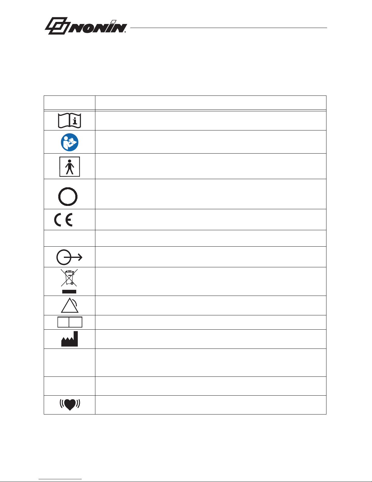
Guide to Symbols .......................................................................................... 4
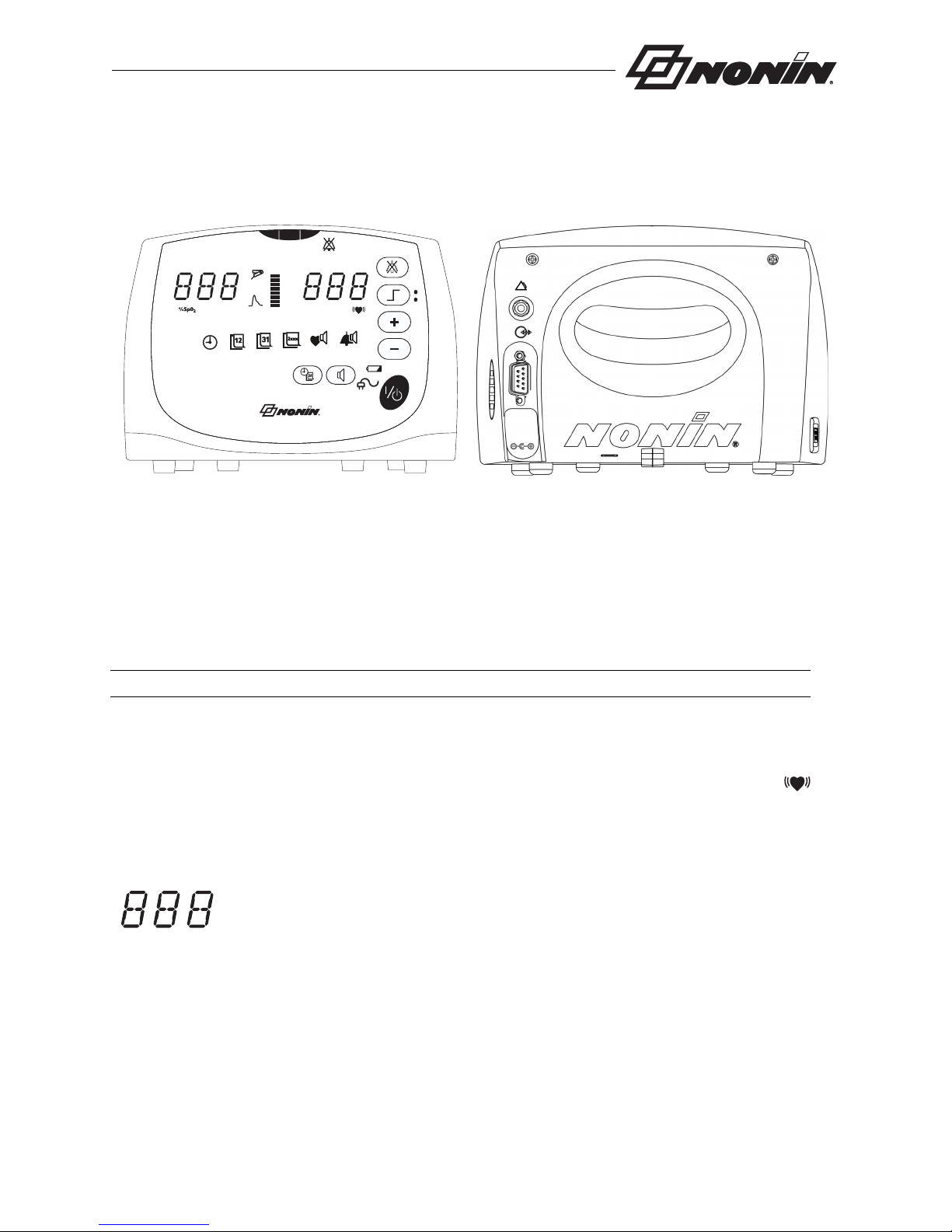
Displays, Indicators, and Controls............................................................... 5
%SpO2 Display....................................................................................................... 5
Pulse Rate Display ................................................................................................. 5
Numeric LEDs ........................................................................................................ 5
Indicators and Icons ............................................................................................... 6
Front Panel Buttons................................................................................................ 7
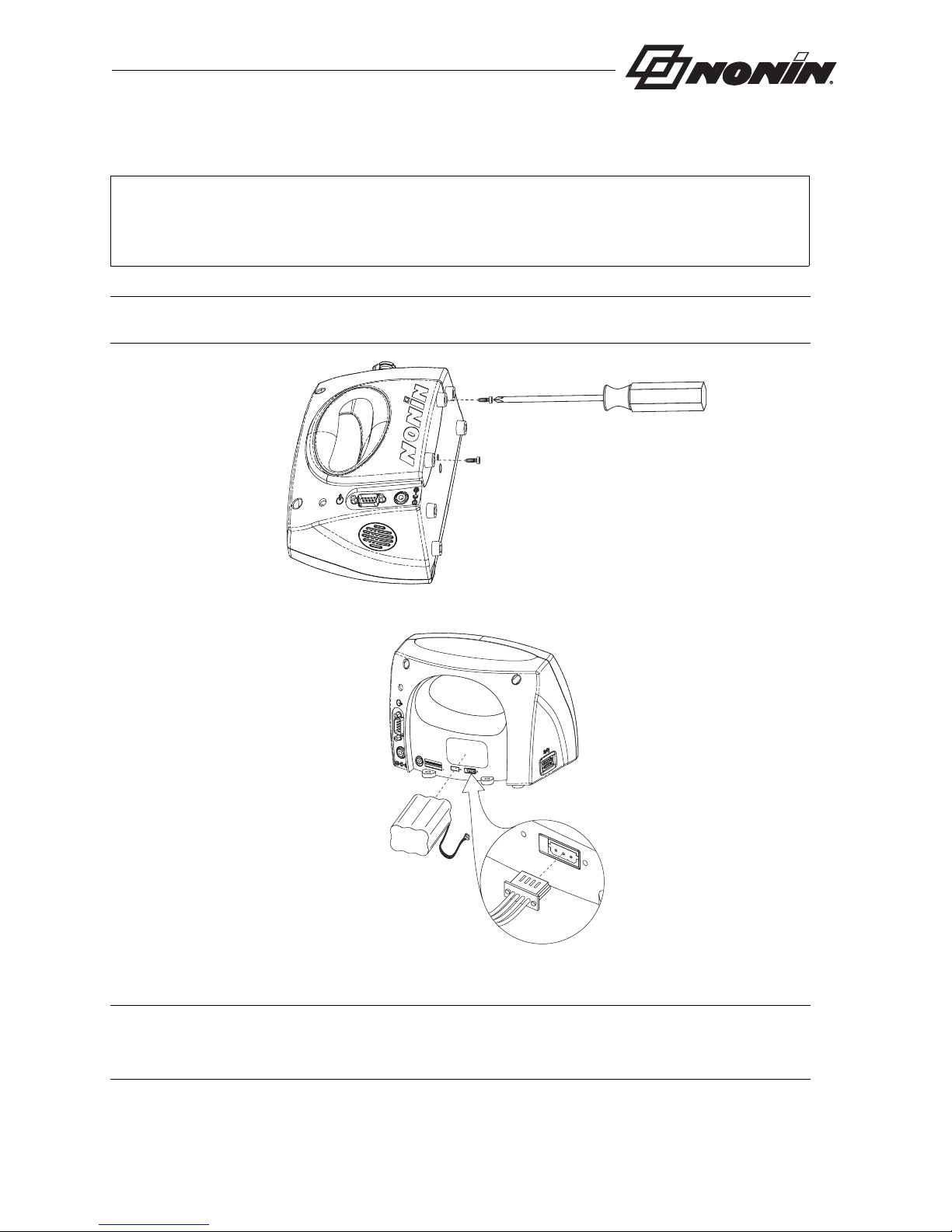
Installing the Batteries .................................................................................. 9
Operating the Avant 9600 ........................................................................... 10
Factory Default ..................................................................................................... 10
User-Defined Defaults .......................................................................................... 10
Operator Functions............................................................................................... 11
Basic Functions................................................................................................. 11
User-Defined Defaults ...................................................................................... 12
Advanced Functions ........................................................................................ 12
Option Switches.................................................................................................... 13
Nurse Call Feature ............................................................................................... 14
Alarms and Limits ................................................................................................. 16
High Priority Alarms.............................................................................................. 16
Medium Priority Alarms ........................................................................................ 16
Watchdog Alarms ................................................................................................. 17
Informational Tones.............................................................................................. 17
Reviewing Setting and Changing Alarm Limits..................................................... 17
SpO2 and/or Pulse Alarm Limits ....................................................................... 17
Pulse and Alarm Volumes................................................................................. 17
Serial Output Rates .............................................................................................. 18
Silencing Alarms................................................................................................... 18
Recalling Previous Settings.................................................................................. 18
Locked and Unlocked Alarms............................................................................... 19
Patient Security Mode .......................................................................................... 19
Viewing and Changing Patient Security Mode.................................................. 19
Error Codes .......................................................................................................... 20
Clearing Error Codes 06, 08, or 10 ................................................................... 20
Memory and Data Output Features ............................................................ 21
Memory Features ................................................................................................. 21
Using nVISION Data Management Software ....................................................... 21
Serial Patient Data Outputs .................................................................................. 22

ii
Contents (Continued)
Print-on-Demand Output....................................................................................22
Real-Time Patient Data Output..........................................................................22
Connecting the Device into a Medical System......................................................23
Using with Philips VueLink ....................................................................................23
Connecting to the VueLink Module....................................................................23
Patient Alarms ...................................................................................................24
Equipment Alarms .............................................................................................24
Care and Maintenance .................................................................................26
Cleaning the Model 9600 ......................................................................................26
Parts and Accessories.................................................................................27
Troubleshooting ...........................................................................................28
Service, Support, and Warranty..................................................................30
Warranty................................................................................................................30
Technical Information ..................................................................................32
Manufacturer’s Declaration ...................................................................................32
Equipment Response Time...................................................................................36
Testing Summary ..................................................................................................37
SpO2 Accuracy Testing .....................................................................................37
Pulse Rate Motion Testing.................................................................................37
Low Perfusion Testing .......................................................................................37
Principles of Operation..........................................................................................37
Specifications ........................................................................................................38
Oximeter ............................................................................................................38
System...............................................................................................................39
Nurse Call..........................................................................................................40

iii
Figures
Figure 1. Avant 9600 Front and Back View................................................................ 5
Figure 2. Installing the Batteries................................................................................. 9
Figure 3. Monitor Rear View..................................................................................... 15
Figure 4. Avant 9600 Connection to Philips Monitor ................................................ 24

iv
Tables
Table 1. Symbols ....................................................................................................... 4
Table 2. Factory Default Settings............................................................................. 10
Table 3. Basic Functions.......................................................................................... 11
Table 4. User-Defined Defaults................................................................................ 12
Table 5. Advanced Functions .................................................................................. 12
Table 6. Option Switches ......................................................................................... 14
Table 7. High Priority Alarms ................................................................................... 16
Table 8. Medium Priority Alarms.............................................................................. 16
Table 9. Error Codes................................................................................................ 20
Table 10. Electromagnetic Emission........................................................................ 32
Table 11. Electromagnetic Immunity........................................................................ 33
Table 12. Guidance and Manufacturer’s Declaration—Electromagnetic Immunity.. 34
Table 13. Recommended Separation Distances ..................................................... 35

1
Indications for Use
Indications for Use
The Nonin® Avant® 9600 Digital Pulse Oximeter is a portable, tabletop device indicated for use
in simultaneously measuring, displaying, and recording functional oxygen saturation of arterial
hemoglobin (SpO2) and pulse rate of adult, pediatric, infant, and neonatal patients in hospitals,
medical facilities, home care, and subacute environments. It may also be used in patient
transport, sleep laboratories, and EMS environments. The Avant 9600 is intended for continuous
monitoring and/or spot-checking of patients during both motion and no-motion conditions, and
for patients who are well or poorly perfused.
Contraindications
Do not use this device in an MR environment.
This device is not defibrillation proof per IEC 60601-1.
Do not use this device in an explosive atmosphere.
Warnings
This device is intended only as an adjunct in patient assessment. It must be used in conjunction with other
methods of assessing clinical signs and symptoms.
Inspect the sensor application site at least every 6 to 8 hours to ensure correct sensor alignment and skin
integrity. Patient sensitivity to sensors may vary due to medical status or skin condition.
Avoid excessive pressure to the sensor application site as this may cause damage to the skin beneath the
sensor.
The device must be able to measure the pulse properly to obtain an accurate SpO2 measurement. Verify that
nothing is hindering the pulse measurement before relying on the SpO2 measurement.
Operation of this device below the minimum amplitude of 0.3% modulation may cause inaccurate results.
General operation of this device may be affected by the use of an electrosurgical unit (ESU).
The use of accessories other than those specified in the Parts and Accessories List may result in increased
electromagnetic emission and/or decreased immunity of this device.
This device should not be used adjacent to or stacked with other equipment. If adjacent or stacked use is
necessary, the device should be observed carefully to verify normal operation.
To a vo i d p at i en t in jur y, us e o n ly N on i n- b ran d ed P ure Lig h t® pulse oximeter sensors. These sensors are
manufactured to meet the accuracy specifications for Nonin pulse oximeters. Using other manufacturers’
sensors can result in improper pulse oximeter performance.
To p re v e nt im p ro per pe r for m an c e a n d/ o r pat i en t in j ury, verify compatibility of the monitor, sensor(s), and
accessories before use.
No modifications to this device are allowed as it may affect device performance.
Do not use a damaged sensor. If the sensor is damaged in any way, discontinue use immediately and replace
the sensor.
Verify all alarm settings and limits during system startup to ensure that they are set as intended.

2
Indications for Use
A hazard can exist if different presets are used on multiple 9600 monitors in one care area.
Do not use the device in or around water or any other liquid when the AC power supply is used.
As with all medical equipment, carefully route patient cables and connections to reduce the possibility of
entanglement, strangulation, or injury to the patient.
Use the device only with Nonin-specified power supplies.
The device’s Nurse Call feature should not be used as the primary source of alarm notification.
All parts and accessories connected to the serial port of the device must be certified according to at least IEC
60950 or UL 1950 for data-processing equipment.
The battery pack must be installed at all times while the device is operating, even when operating on AC power.
The audible alarms and memory will not function if batteries are removed from the device.
To c om p ly w it h re l ev a n t p ro d u ct sa f e ty stan dar d s, ens u re that all alarm volumes are set appropriately and are
audible in all situations.
Cautions
When mounting the monitor to a mobile pole, mounting the monitor higher than 1. 5 meters (5 feet) or mounting
more than 2 kilograms (4.5 pounds) of equipment onto the pole may result in tipping, damage to the equipment,
or injury.
Review all limits to ensure they are appropriate for the patient.
Setting alarm limits to extremes can render the alarm system useless.
This device is designed to determine the percentage of arterial oxygen saturation of functional hemoglobin.
Factors that may degrade pulse oximeter performance or affect the accuracy of the measurement include the
following:
The device may not work when circulation is reduced. Warm or rub the finger, or reposition the device.
In some circumstances, the device may interpret motion as good pulse quality. Minimize patient motion as much
as possible.
Do not autoclave or immerse this device in liquid or use caustic or abrasive cleaning agents.
A functional tester cannot be used to assess the accuracy of a pulse oximeter monitor or sensor.
Warnings (Continued)
- excessive ambient light
- excessive motion
- electrosurgical interference
- blood flow restrictors (arterial catheters, blood
pressure cuffs, infusion lines)
- moisture in the sensor
- improperly applied sensor
- incorrect sensor type
- poor pulse quality
- venous pulsations
- anemia or low hemoglobin concentrations
- cardiogreen and other intravascular dyes
- carboxyhemoglobin
- methemoglobin
- dysfunctional hemoglobin
- artificial nails or fingernail polish

3
Indications for Use
This equipment complies with IEC 60601-1-2 for electromagnetic compatibility for medical electrical equipment
and/or systems. This standard is designed to provide reasonable protection against harmful interference in a
typical medical installation. However, because of the proliferation of radio-frequency transmitting equipment and
other sources of electrical noise in healthcare and other environments, it is possible that high levels of such
interference due to close proximity or strength of a source might disrupt the performance of this device. Medical
electrical equipment needs special precautions regarding EMC, and all equipment must be installed and put into
service according to the EMC information specified in this manual.
Portable and mobile RF communications equipment can affect medical electrical equipment.
Follow local, state and national governing ordinances and recycling instructions regarding disposal or recycling
of the device and device components, including batteries.
In compliance with the European Directive on Waste Electrical and Electronic Equipment (WEEE) 2002/96/EC,
do not dispose of this product as unsorted municipal waste. This device contains WEEE materials; please
contact your distributor regarding take-back or recycling of the device. If you are unsure how to reach your
distributor, please call Nonin for your distributor’s contact information.
If the device fails to respond as described, discontinue use until the situation is corrected by qualified personnel.
This device is a precision electronic instrument and must be repaired by trained Nonin personnel only. Field
repair of the device is not possible. Do not attempt to open the case or repair the electronics. Opening the case
may damage the device and void the warranty.
To p re v en t pot en t ial l o s s o f m on i t ori ng , do not use ear clip or reflective sensors on pediatric or neonatal patients.
This product complies with ISO 10993.
Radios and cell phones or similar devices can affect the equipment and must be kept at least 2 meters (6.5 feet)
away from equipment.
Failure of a network data coupling (serial cable/connectors/wireless connections) will result in loss of data
transfer.
Cautions (Continued)

4
Guide to Symbols
Guide to Symbols
This table describes the Nonin symbols located on the Avant 9600. See Section titled Displays,
Indicators and Controls for detailed information about functional symbols.
Table 1: Symbols
Symbol Description
Consult Instructions for Use
Follow Instructions for Use
Type BF Applied Part (Patient isolation from electrical shock).
UL Mark for Canada and the United States with respect to electric shock, fire,
and mechanical hazards only in accordance with UL 60601-1 and CAN/CSA
C22.2 No. 601.1.
CE Marking indicating conformance to IEC directive No. 93/42/EEC
concerning medical devices.
Serial Number (located under the back cover).
Signal Output (located on back of device).
Indicates separate collection for electrical and electronic equipment (WEEE).
Alarm Call (located on back of device).
Authorized Representative in the European Community.
Manufacturer
IP22 Protected against vertically falling water drops when enclosure is tilted up to
15 degrees and against access to hazardous parts with a finger per
IEC 60529.
%SpO2%SpO2 Display
Pulse Rate Display
C
L
A
S
S
I
F
I
E
D
US
C
UL
01230123
SN
EC
REP

5
Displays, Indicators, and Controls
This section describes the displays, indicators, and controls for the Avant 9600.
Figure 1: Avant 9600 Front and Back View
%SpO2 Display
The %SpO2 Display is located on the front panel of the Avant 9600 and is identified by the
%SpO2 symbol. This display shows blood oxygen saturation, from 0 to 100 percent. The numeric
LEDs blink during SpO2 alarm conditions.
NOTE: LED means “light-emitting diode”.
Pulse Rate Display
The Pulse Rate Display, located on the front panel of the Avant 9600, is identified by the
symbol. This display shows the pulse rate in beats per minute, from 18 to 300. The numeric
display blinks during pulse rate alarm conditions.
Numeric LEDs
Green numeric LEDs display %SpO2 and pulse rate values. When setting the
device, the LEDs also display values for alarm limits, volume, and date and
time settings.
Red, rapidly blinking LEDs indicate a High Priority patient alarm. Values are
displayed in amber when reviewing or changing limits.
9600

6
Displays, Indicators, and Controls
Indicators and Icons
Main Alarm LED
Red, rapidly blinking LEDs indicate a High Priority patient alarm. Amber
slowly blinking LEDs indicate a medium priority (equipment) alarm.
Pulse Quality LED
This LED blinks to indicate an inadequate pulse signal. If there is a
sustained period of inadequate pulse signals, this LED will illuminate solid.
Pulse Oximeter Sensor LED
The Pulse Oximeter Sensor LED indicates when a sensor has become
disconnected, has failed, is misplaced or is not compatible with this
monitor.
Pulse Strength Bar Graph LED
This 8-segment tricolor bar graph indicates pulse strength as determined
by the oximeter. The bar graph changes color based upon the strength of
the pulse. The color and height of the Pulse Strength Bar Graph is
proportional to the pulse amplitude. For low pulse amplitude, the device
goes into High Priority Alarm mode:
Green = a good pulse strength
Amber = a marginal pulse strength
Red = an inadequate pulse strength, high priority alarm
The Pulse Strength Bar Graph LED also indicates the battery capacity in
12% increments in green. Amber represents the depleted capacity of the
battery and green indicates the available battery capacity.
Alarm Silence LED
This amber LED indicates that the audible alarm is silenced for two
minutes when it blinks. When lit solid, the Alarm Silence LED indicates that
the audible alarm volume is set to less than 45 dB.
Time, Month, Day, and Year LEDs
These amber LEDs indicate that the Avant 9600’s Time, Month, Day, or
Year displays can be reviewed or adjusted using the Plus (+) and Minus (-)
buttons.
Pulse Volume LED
This amber LED indicates that the Pulse Volume can be reviewed or
adjusted using the Plus (+) and Minus (-) buttons.

7
Displays, Indicators, and Controls
Front Panel Buttons
Alarm Volume LED
This amber LED indicates that the Alarm Volume can be reviewed or
adjusted using the Plus (+) and Minus (-) buttons.
AC Power Supply LED
This green LED is displayed when an external power supply is providing
power to the Avant 9600. Any time this LED is displayed, the battery pack
is charging.
NOTE: When the external power supply is disconnected, the device
automatically switches to battery power without loss of functionality.
Battery LED
This amber LED indicates marginal battery capacity when blinking. When
solidly lit, the LED indicates that the battery pack is not installed. This LED
does not indicate that the device is running on battery power. New battery
packs must complete one charge/discharge/recharge cycle before the
Battery LED displays the actual capacity.
WARNING: The battery pack must be installed at all times while the device is
operating—even when operating on AC power. The audible alarms and memory will
not function if batteries are removed from the device. DO NOT use this device without
batteries.
ON/STANDBY
• Press Once: Turns the device on
• Hold 1 second: Turns the device off
• Hold 5 seconds: Turns the device off when in Patient Security mode
• Press momentarily while the unit is on:
• Indicates the battery capacity in green, in 12% increments for
3seconds
• Initiates Print-on-Demand feature
• Records event marker
Time/Date
This button displays the time and date. Year, month, day, hour, and minute
can be set using the Plus (+) and Minus (-) buttons.

8
Displays, Indicators, and Controls
Volume
This button allows users to set and review the pulse or alarm volume,
indicated by the designated LED.
Alarm Silence
• Engages the 2-minute alarm silence automatically at start-up
• Changes the alarm from silenced to audible
• Silences the alarm for 2 minutes
• Cancels audible and visual alarms, when in Locked Alarms mode, if the
alarm condition is no longer present.
Alarm Limits Button and Indicator
The upper LED on the Alarm Limits button indicates the upper alarm limit,
and the lower LED indicates the lower alarm limit for SpO2 and heart rate
measurements. The limits can be adjusted using the Plus (+) and Minus (-)
buttons. Pressing the Alarm Limits buttons allows the user to manually
advance through the alarm settings to review and set alarm limits. The limit
values are displayed in amber.
Plus Button and Minus Button
The Plus (+) and Minus (-) buttons are used to adjust time, date, volume,
upper and lower alarm limits, and data output settings. Pressing either
button, when the device is not in program mode, adjusts the intensity of the
LED displays.

9
Installing the Batteries
NOTE: New battery packs must be fully charged before use; minimum recharge time is
4 hours.
Figure 2: Installing the Batteries
NOTES:
• Contact Nonin
to purchase or replace battery packs.
• Reposition the back cover carefully, and tighten the screws firmly. Do not over-tighten.
WARNING: The battery pack must be installed at all times while the device is
operating—even when operating on AC power. The audible alarms and memory will
not function if batteries are removed from the device. Do not use this device without
batteries.

10
Operating the Avant 9600
Press the ON/STANDBY button to perform the start-up (initialization) sequence. Verify that all
LEDs, except the AC Power Supply LED, are illuminated and the unit beeps three times during
the start-up sequence. Contact Nonin Technical Service for assistance.
Use the following procedure to verify that the pulse oximeter sensor is functioning properly.
1. Ensure that the Avant 9600 is on, and the sensor is connected to the monitor.
2. Apply the pulse oximeter sensor to the patient.
3. Verify that SpO2 and pulse rate values are displayed, and the pulse strength bar graph
LED is activated.
Factory Default
In Factory Default, all adjustable alarm and volume parameters are set at their default values.
Factory Default settings are in the table below:
Factory default is indicated by option switch 4 in the DOWN position. Refer to Options Switches
Section.
User-Defined Defaults
User-Defined Defaults (option switch 4 in the UP position), alarm limits and volume settings can
be adjusted. To set user-defined defaults, enter limit settings for SpO2 and pulse rate alarms,
alarm volume and pulse rate volume. The device will not return to operating mode until all user-
defined default limits are set. The programmed limits are the defaults until the device is turned
off. To return to Factory Defaults, turn the device off, move Option Switch 4 to the Down position
and turn the device on.
WARNING: Verify all alarm settings and limits during system startup to ensure that
they are set as intended.
Table 2: Factory Default Settings
Description Default
SpO2 Upper Alarm Limit Off
SpO2 Lower Alarm Limit 85%
Pulse Upper Alarm Limit 200 BPM
Pulse Lower Alarm Limit 50 BPM

11
Operating the Avant 9600
Operator Functions
Basic Functions
The Avant 9600 basic functions are described in the table below.
NOTE: When option switch 6 is in the DOWN position, the display intensity is automatically
reduced when changing between AC and battery power.
Table 3: Basic Functions
Function Button Instruction
Turns device on and off Using the ON/STANDBY button:
• Press once (turns the device on)
• Hold 1 second (turns the device off)
• Hold 5 seconds (turns the device off when in
Patient Security mode)
Battery capacity Briefly press the ON/STANDBY button while the device
is on to display battery capacity.
Print-on-Demand Press the ON/STANDBY button while the device is on.
Record an event marker Press the ON/STANDBY button while the device is on.
Silence audible alarms Press the Alarm Silence button.
Cancel locked alarms Press the Alarm Silence button.
Display intensity
(brightness)
Press the Plus or Minus button.
or

12
Operating the Avant 9600
User-Defined Defaults
Advanced Functions
Table 4: User-Defined Defaults
Function Button Instruction
Set alarm limits Press the Alarm Limits button to scroll
through the Limits menu. Adjust alarm
limits with the Plus or Minus button.
Set pulse and alarm
volumes
Press the Volume button to select pulse
or alarm volume. Adjust the selected
volume with the Plus or Minus button.
Set time and date Press the Time/Date button to scroll
through the Time/Date menu. Adjust the
time and date with the Plus and Minus
buttons.
Table 5: Advanced Functions
Function Button Action
Recall Previous
Alarm Limits
•Press and hold both the Alarm
Limits and Minus buttons for three
seconds.
- or -
•Press and hold both the Alarm
Limits and ON/STANDBY buttons
when turning on the device.
or
then
or
then
or
then
+
+
or

13
Operating the Avant 9600
Option Switches
The Avant 9600 contains eight option switches located under the back cover (See “Installing the
Batteries” for instructions on removing the back cover). The device is supplied with all option
switches in the DOWN position.
Memory Download
and/or Clear Menu
Nonin nVISION® software is required for
memory download.
•Press and hold the Time/Date
button while turning on the device.
•Follow the display prompts after the
PLy bAC message clears.
Note: Memory cannot be cleared when
the device is in Patient Security mode.
Patient Security •To access Patient Security mode,
press and hold both the Alarm
Limits and Time/ Date buttons for
5 seconds. The current Patient
Security mode displays in green on
the Numeric LEDs:
•“111 111” (enabled mode)
displays when Patient Security
is on.
•“000 000” (disabled mode)
displays when Patient Security
is off.
•To change Patient Security mode,
press the Volume button while the
mode is displayed. The new
Patient Security mode (Enabled or
Disabled) is then displayed in
amber on the Numeric LEDs.
Serial Output • Simultaneously press and hold
both the Time/Date and Volume
buttons for three seconds. Adjust
the serial output rate with the Plus
and Minus buttons.
Table 5: Advanced Functions (Continued)
Function Button Action
+
+
+

14
Operating the Avant 9600
Nurse Call Feature
The Avant 9600 features a nurse call circuit that can be connected to a facility nurse call system,
allowing alarm conditions to be recognized at a central monitoring location and on the
Avant 9600. Two switches located on the back of the 9600 under the back cover allow users to
activate the Nurse Call feature.
Table 6: Option Switches
Switch Function
Switch 1 Alarm Disable
Up—Alarm volume may be disabled
Down—Alarm volume cannot be set to zero (disabled)
Switch 2 Normal / Slow SpO2 Averaging
Up—Slow Averaging (8 beat exponential average)
Down—Normal Averaging (4 beat exponential average)
Switch 3 Alarm Unlocked / Locked
Up—Alarms Locked
Down—Alarms Unlocked
Switch 4 Factory / User-Defined Defaults
Up—User-Defined Defaults for Alarm Limits and Volume Settings
Down—Factory Defaults for Alarm Limits and Volume Settings
Switch 5 US / International Date Format
Up—International Date Format
Down—US Date Format
Switch 6 Power Saving During Battery Use (Dims Display)
Up—Power Saving Disabled
Down—Power Saving Enabled
Switch 7 Nurse Call Output
Up—Continuous
Down—One second audible alarm at 60 second intervals
Switch 8 Serial Data Output
Up—Fast SpO2 and pulse rate output
Down—SpO2 and pulse rate output, as determined by the position of option
switch 2
Other manuals for Avant 9600
2
Table of contents
Other Nonin Medical Equipment manuals

Nonin
Nonin 3100 WristOx User manual

Nonin
Nonin 2500A PalmSAT User manual

Nonin
Nonin 7500FO User manual

Nonin
Nonin SenSmart X-100 Manual

Nonin
Nonin 8500AV User manual

Nonin
Nonin Onyx II User manual

Nonin
Nonin CO-Pilot H500 User manual

Nonin
Nonin 7500 User manual

Nonin
Nonin 2500 PalmSAT User manual

Nonin
Nonin 8500 User manual
Popular Medical Equipment manuals by other brands

Tactile Medical
Tactile Medical Flexitouch Plus user guide

Barco
Barco Eonis MDRC-2122 BL user guide

Rehabed
Rehabed Taurus Junior Instructions for use

BEYES
BEYES APEXPILOT ALL-IN-ONE Operation manuals

Weinmann
Weinmann SOMNOsmart 2 Description and instructions for use

Otto Bock
Otto Bock Manu Immobil Long Instructions for use