manuals.online logo
Brands
  1. Home
  2. •
  3. Brands
  4. •
  5. Nordson
  6. •
  7. Melting Machine
  8. •
  9. Nordson 2302 User manual

Nordson 2302 User manual

Series 2300 Applicator
with SP Pump
Part 106 701 D
NORDSON CORPORATION. AMHERST, OHIO. USA
SERVICES PROVIDED TO NORDSON CUSTOMERS
Customer Support Before And After The Sale
For more than 35 years Nordson has offered unparalleled service to its customers before, during
and after the sale. Nordson representatives will work with you to choose the best system for your
application. We’ll assist you during start-up and help train your employees to maintain and
operate the equipment. Plus, parts and service are only a phone call away from one of our
strategically located sales and service centers.
System Engineering
Custom designs and modification of standard equipment are available to meet your particular
needs. From a complete new system for automotive assembly to a special nozzle used in the
production of diapers, Nordson has the expertise to integrate adhesive and sealant equipment with
your manufacturing operation.
Parts And Accessories
In addition to standard replacement parts, many accessories are available to help improve
productivity and reduce downtime. For example, heated and non-heated in-line filters reduce
stoppages from clogged nozzles, and nozzles in multi-orifice, offset, right-angle and other designs
are available for special needs. Also, gloves, solvent, spare parts kits and other components are in
stock for immediate delivery. Conversion kits for tapers, labelers and box-forming equipment are
also available.
To help you eliminate downtime and costly inplant repairs, Nordson has developed a Rebuilt
Exchange (RBXSM)Program* which can save you up to 50 percent of the cost of new equipment.
You may trade in your old worn units, hoses and guns for rebuilt Nordson equipment which has
the same warranty as new equipment.
The Nordson Package of ValuesfM
From specifications assistance to post-installation troubleshooting, the Nordson Package of Values
is designed to keep our customers productive and profitable by providing:
0 Carefully engineered, durable products *
0 Strong service support
l The back-up of a well-established international company with financial and technical strength
0 A corporate commitment to deliver what was specified
*This service not available in all countries.
306-l 8-662 ONORDSON CORPORATION 1993
All Rights Reserved Issued 2/93
770−497−3400 770−497−3500
770−497−3400 770−497−3500
3/05
US contact numbers updated 3/05
General Information . -03.
HOW TO USE THIS MANUAL
The Page Numbering System The page number is composed of two parts: the section number
followed by the section page. Page 5-3, for example, is the third page
in Section 5.
Finding Information Quickly Before trying to find information in this manual, become familiar with its
organization and contents.
Afterwards:
1. Use the Brief Summary of Manual Contents (below) to determine
which section contains the information you are seeking.
2. Use the tabs to find the section that contains the desired information.
On the first page of each section is a Table of Contents for that
section. It gives the starting page number of all the material in the
section.
Brief Summary of Manual
Contents The following summary lists the most important information in each
section and provides a general idea of where to look for material not
included in the summary.
Section I: Safety Summary
Section2: Equipment
Familiarization
Secfion 3: lnsfallafion
l General description
Explanation of safety symbols
Safety during installation, operation and servicing
Safety in handling solvents1
Description of equipment and features
Operation
Glossary of terms
Unpacking and inspection
Installing the unit, hoses and guns
Electrical installation
Q Nor&on Corporation 1994
AU Rights Reserved PIN 106 701A
41-2300%’ - tssued 1194
o-4 General lnformation
Brief Summary of Manual
Contents
(continued)
Section4: OperatingInstructions
Section5: Preventive Maintenance
Section 6: Troubleshooting
Section 7: Disassembly and Repair
Section 8: Illustrated Parts Lists
Section 9: TechnicalData
Section 10:OptionalParts and
Equuipment
l Loading adhesive, including flushing the system
l Daily operating procedures
l General maintenance and filter flushing procedures
Troubleshooting functional problems
Troubleshooting adhesive and adhesive-application problems
Wiring diagrams and schematics
.
Mechanical repairs
Electrical repairs
Gun heater and RTD replacement
Illustrations of the unit and its subassemblies
Matching parts lists
Listings of recommended spare parts and service items/kits
Mechanical specifications
Electrical specifications
Material safety data information about Nordson Type R solvent
l Listings of various field-installed options, guns, hoses, filters etc.
NOTE: If at any time you are unable to find needed information in this
manual, contact your local Nordson representative or your regional
sales office.
PIN 106 701A
41-23OOSP - tssued llg4 Q Nordson Corporation 1994
All Rights Reserved
SECTION I
Safety Instructions
1. Operate safely! ........................................ l-l
2. Safety symbols ...................... ..c ............... 1-l
3. Intended use ......................................... l-2
4. Installation and electrical connections ..................... .l -2
5. Operation ............................................ l-3
Action in the event of unit malfunction .................... .l-3
Danger of burns .................................... .l-3
6. Maintenance/Repair .................................. .l-4
7. Cleaning ............................................ l-4
8. Thermoplastic hot melt material ......................... .l-5
0 Nordson Corporation 1994 P/N 106 701A
AU Rights Resewed 41-2300SP - Issued 1194
This Page Intentionally
Left Blank
PM 106 701A 0 Nordson Corporation 1994
41-2300SP -issued l/94 All Rights Reserved
Safety Instrirctions l-l
Section 1
Safety Instructions
1.Operatesafely! Safety recommendations contained in this section and throughout the
manual apply to tasks that may be performed on or with the unit or with
materials used with the unit. IT IS VERY IMPORTANT THAT THESE
SAFETY RECOMMENDATIONS ARE ALWAYS FOLLOWED.
FAILURE TO DO SO COULD RESULT IN PERSONAL INJURY.
AND/OR DAMAGE TO THE UNIT OR OTHER EQUIPMENT.
With this in mind, here are some basic safety recommendations:
l Read and become familiar with this Safety Instructions Section prior
to installing, operating, maintaining or repairing the unit.
l Store this manual within easy reach of personnel operating or
maintaining the unit.
l Be familiar with and always observe safety symbols.
l Wear adequate personal protective equipment and clothing such as
safety goggles and gloves.
l Familiarize yourself with and follow all safety instructions prescribed
by your company, general accident prevention regulations and
government safety regulations.
2. Safety symbols The following symbols are used throughout the manual to warn against
dangers or possible sources of danger. Become familiar with them!
Failure to heed a warning symbol could lead to personal injury and/or
damage to the unit or other equipment.
WARNING: Failure to observe may result in personal injury,
death or equipment damage.
WARNING: Risk of electrical shock. Failure to observe may
result in personal injury or death.
WARNING: Disconnect equipment from line voltage. Failure
to observe may result in equipment damage, personal injury
or death.
WARNING: Hot. Risk of burns. Wear protective
clothing/safety goggles (ANSI 287.1-l 989 or
equal)/protective gloves (P/N 902 514) depending on the
symbol shown.
0 Nordson Corporation 1994
AU Rights Reserved P/N 106 701A
41.2300SP - Issued 11’94
I-2 Safety Instructions
2. Safetysymbols
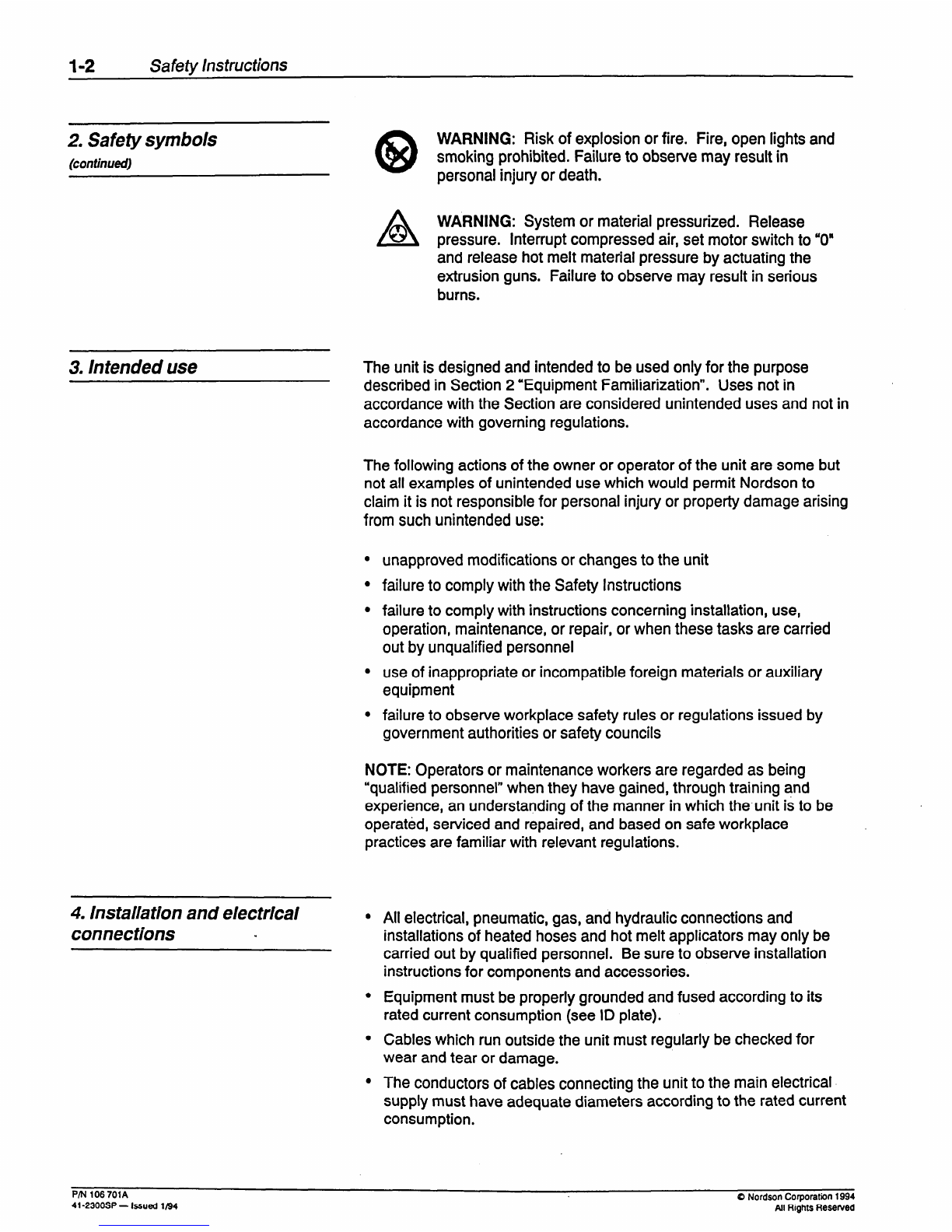
(continueoy WARNING: Risk of explosion or fire. Fire, open lights and
smoking prohibited. Failure to observe may result in
personal injury or death.
n
0WARNING: System or material pressurized. Release
pressure. Interrupt compressed air, set motor switch to “0”
and release hot melt material pressure by actuating the
extrusion guns. Failure to observe may result in serious
burns.
3. Intended use The unit is designed and intended to be used only for the purpose
described in Section 2 “Equipment Familiarization”. Uses not in
accordance with the Section are considered unintended uses and not in
accordance with governing regulations.
The following actions of the owner or operator of the unit are some but
not all examples of unintended use which would permit Nordson to
claim it is not responsible for personal injury or property damage arising
from such unintended use:
l unapproved modifications or changes to the unit
l failure to comply with the Safety Instructions
l failure to comply with instructions concerning installation, use,
operation, maintenance, or repair, or when these tasks are carried
out by unqualified personnel
l use of inappropriate or incompatible foreign materials or auxiliary
equipment
l failure to observe workplace safety rules or regulations issued by
government authorities or safety councils
NOTE: Operators or maintenance workers are regarded as being
“qualified personnel” when they have gained, through training and
experience, an understanding of the manner in which the unit is to be
operated, serviced and repaired, and based on safe workplace
practices are familiar with relevant regulations.
4. Installationand electrical
connections ” l All electrical, pneumatic, gas, and hydraulic connections and
installations of heated hoses and hot melt applicators may only be
carried out by qualified personnel. Be sure to observe installation
instructions for components and accessories.
Equipment must be properly grounded and fused according to its
rated current consumption (see ID plate).
Cables which run outside the unit must regularly be checked for
wear and tear or damage.
The conductors of cables connecting the unit to the main electrical
supply must have adequate diameters according to the rated current
consumption.
PM 106 701A
41-2300SP - Issued 1194 0 Nordson Corporation 1994
All Rights Resented
Safety Instructions I-3
4. Installation and electrical
connections
(continued)
l Cables must never be squeezed or pinched. They should be located
or positioned to eliminate the opportunity for an operator to stumble
or trip.
l A disconnect switch with lockout capability must be provided
between the power source and the equipment.
a WARNING: If the installation is not carried out according to
t instructions, especially in case of electrical connections, this
l will result in imminent danger of serious personal injury
including death.
5. Operation The unit should be operated according to relevant instructions and by
qualified personnel.
NEVER have the unit operated by personnel under the influence of
substances reducing their reaction times, or who are not able to
operate the equipment for physical reasons.
At regular intervals, check protective and warning devices to
determine that they are in a functioning condition. DO NOT
OPERATE THE UNIT IF THESE DEVICES ARE NOT
FUNCTIONING PROPERLY.
When the removal of safety equipment is required for installation,
maintenance, or repair of the unit, it must be reconnected
immediately upon completion of the work and prior to unit start-up.
In a humid environment, only equipment featuring a corresponding
class of protection may be operated.
Do not operate the unit in an explosive environment.
Keep endangered parts of the body or clothing away from rotating
parts. Take off wrist watches, rings, necklaces, or similar pieces of
jewelry and pin up or cover long hair before performing any work on
or with the unit.
To carry out measurements on work pieces, switch off the unit and
wait until it comes to a standstill.
Never point hand guns or applicator nozzles at yourself or other
persons.
Action in the even of unit
malfunction
Danger of burns
In the event the unit experiences a malfunction, switch off the unit
immediately.
l Switch off the main switch or, if available, the emergency turnoff
switch or use other safety equipment to stop the unit.
l After turning the unit off and prior to switching it on again, the
malfunction has to be eliminated by qualified personnel.
Contact with hot areas of the hot melt applicator as well as to the hot
melt material may produce a severe skin burn.
l Take utmost care when using hot melt material. Even solidified
material may still be very hot.
8 Nordsm Corporation 1995
All Rights Resewed PIN 106 7018
41-2300SP - Issued 1195
1-4 Safety Instructions
Danger of bums l Always wear protective clothing which safely covers all endangered
(continued) body parts.
In case of burns:
l Immediately cool affected skin areas using cold, clean water.
l Do not forcefully remove hot melt material from the skin.
l Immediately seek medical attention.
6. Maintenance/Repair Allow only qualified personnel to perform maintenance, repair and
troubleshooting. All activities should only be carried out wearing
personal protective clothing and equipment and when the equipment is
switched off and unpressurized.
n WARNING: Even when the main switch is set to OFF there
/i remains residual voltage inside the switchboard. So, on
principle, carry out the following work prior to maintenance
and repair:
Disconnect, lock out and tag external power supply.
To ensure the external power supply is disconnected, attempt to
operate the unit. Ifthe unit does not energize, proceed with
maintenance or repair work.
If the unit energizes, repeat the disconnect, lock out and tag
procedure. Retest the unit.
Manually actuate the applicators/hand guns to release the system
pressure in the entire unit.
Secure pneumatically or hydraulically operated equipment against
uncontrolled movement.
Only use spare parts which do not compromise the safety of the unit.
A list of Nordson spare parts is provided in Section 8 of this manual.
ALWAYS use a rubber handle screwdriver when removing or
installing components.
7. Cleaning NOTE: Always refer to the Material Safety Data Sheet or material
information sheet before working with the material.
n WARNING: Never clean any aluminum part or flush any
t
l system using halogenated hydrocarbon solvents. Examples
of common halogenated hydrocarbons are
dichloromethyline, 1,l ,l -trichloroethylene, perchloroethyline.
Halogenated hydrocarbons may react violently with
aluminum parts.
l NEVER use an open flame to clean the unit or components of the
unit.
l Use only cleaning solvents designed or intended to be used withthe
hot melt material being used in the unit. NEVER USE PAINT
SOLVENTS UNDER ANY CIRCUMSTANCES.
P/N 106 7OlA
41.2300SP - Issued 1194 Q Nordson Corporation 1994
All Rights Resewed
Safety Instructions I-5
7. Cleaning
(continued)
l Note the flash point of the cleaning solvent used. Only use a
controlled heating method to heat solvents.
l Ensure sufficient room ventilation to draw off generated vapors.
Avoid prolonged breathing of vapors.
WARNING: Fire, open lights and smoking are prohibited
when cleaning solvents are used. Risk of explosion or fire.
Failure to observe may result in personal injury or death.
8. Thermoplastichot melt
material NOTE: Always refer to the Material Safety Data Sheet or material
information sheet before working with the material.
l Ensure the work area is adequately ventilated.
l Do not exceed recommended processing temperatures. Doing so
creates a danger to personnel due to decomposition of the material.
Q Nordson Corporation 1994
All Rights Reserved PIN 106 701A
41-2300SP - Issued 1194
1-6 Safety Instructions
This Page Intentionally
Left Blank
PIN 106 701A
4t-23OOSP - Issued l/94 0 Nordson Corporation 1994
All Rights Reserved
SECTION 2
Equipment Familiarization
1. Introduction .......................................... 2-1
2. Functional description of standard features ................. 2-2
Hot melt tank ....................................... .2-2
Hot melt adhesive pump .............................. .2-2
Distribution manifold .................................. 2-4
Tank, hose, and gun temperature controls ................. 2-4
Automatic gun hoses ................................. 2-5
Handgun hoses ...................................... 2-5
Automatic extrusion guns (H20 and H200) ................ .2-6
Manual extrusion gun ................................. 2-7
3. Glossary ............................................ 2-8
List of Illustrations
Figure 2.1 - Series 2300 Hot Melt Applicator
(Model 2305 Shown) . . . . . . . . . . . . . . . . . . . . . . . . . . . . . . . . . .
2-1
Figure 2.2 - Air-Driven, Dual-Acting Piston Pump
During Upstroke . . . . . . . . . . . . . . . . . . . . . . . . . . . . . . . . . . . . . . .
2-3
Figure 2.3 - Air-Driven, Dual-Acting Piston Pump
on Downstroke .,..................................... 2-3
Figure 2.4 - Model 2305 Indicator Panel with
Parent Machine Interlock (PMI) and Low Level Indicator Options. 2-4
Q Nordson Corporation 1994 P/N 106 7OlA
AU Rights Reserved 41-2300SP - Issued l/94
This Page Intentionally
Left Blank
PM 106 701A 0 Nordson Corporation 1994
41-23OOSP - Issued ll94 All Rights Reserved
Equipment Familiarization 2-3
Hot melt adhesive pump
(continued)
AIRCYUNOER
I CRosSCiVERlUf3E
Figure 2.2 -Air-Driven, Dual-Acting
Piston Pump During Upstroke
The pump delivers adhesive to the distribution manifold on both the
upstroke and the downstroke of the piston. On the upstroke (see Figure
2.2) compressed air enters the air cylinder below the air piston, forcing
it upward. As the attached pump shaft moves up, the large ball check
valve is lifted off its seat, sucking adhesive into the chamber from the
applicator tank. The small ball check valve remains on its seat during
this time because the pump shaft is moving up. The upward movement
of the plunger at the lower end of the pump shaft also pushes the .
adhesive above it into the crossover tube and from there into the
distribution manifold.
In the downstroke of the pump (see Figure 2.3) compressed air enters
the air cylinder above the air piston, forcing it down. As the attached
pump shaft moves down, the adhesive pressure forces the large ball
check valve against its seat and the small ball check valve off its seat,
allowing the adhesive to move up the pump cylinder and into the
crossover tube. It then passes through a filter in the distribution
manifold and from there to the hose(s) and gun(s).
Overpressure protection is provided by a relief valve in the distribution
manifold. It opens at 1,500 psi (10.3 MPa) to relieve system pressure
by allowing adhesive back to the adhesive tank.
AIRCYLINDER-
AIR REDUIAT’CR
SWSINO DMC
DIREC’TlON OF TRAVEL -
.
‘:#...-A n r) A :- me:. .a- m. .-I A -A?--
ryurt: L.3 - ml-UIIV~II, uuawtcrmng
-
Piston Pump on Downstroke
0 Nordson Corporation 1994
AU Rights Reserved P/N 106 701A
41-2300SP - Issued 1194
2-4 Equipment Familiarization
Distributionmanifold
Tank,hose, and gun temperature
controls
NO. 4 HOSE CHANNEL
--YELLOW LED
--NO. 4 GUN CHANNEL
NO. 5 HOSE CHANNEL. YELLOW LED
-- NO. 5 GUN CHANNEL
TANK CHANNEL
-- YEUOW LED
“FAULT” LIGHTd RED LED
“WAIT” LIGHT FOR
-- PARENT MACHINE
INTERLOCK
c---LOW LEVEL
INDICATOR
Figure 2.4 - Model 23’05Indicator Panel with
NO. 1 HOSE CHANNELd YELLOW LED
-- NO. 1 GUN CHANNEL
. NO. 2 HOSE CHANNEL
YELLOW LED
-- NO. 2 GUN CHANNEL
. NO. 3 HOSE CHANNEL
YELLOW LED
-- NO. 3 GUN CHANNEL
Parent Machine Interlock (PM/) and Low
Level Indicator Options:.
An aluminum manifold assembly mounted on the bottom of the hot melt
tank receives hot adhesive from the air-driven pump, filters it, and
distributes it to the heated hoses and extrusion guns. Because the
distribution manifold is mounted to the tank, it is indirectly heated by the
tank heaters.
The filter consists of a core and fine mesh screen to filter out
contaminants and char. The filter is threaded into a sleeve to prevent
overtorquing and allow easy removal for inspection and cleaning.
A drain valve in the manifold allows material to be pumped through the
filter assembly without the use of the hoses and extrusion guns. The
valve also provides a convenient method to relieve pressure in the
system during maintenance operations.
The manifold contains six ports for connecting hot melt hoses: four in
the side of the manifold and two in the bottom.
The temperature controller in Series 2300 applicators is a solid-state
device that monitors and controls the temperatures within the hot melt
tank and heated hoses and guns. Temperature is sensed in the tank
and in each of the hoses and guns by a resistance temperature
detector (RTD) in each component. Each of these heating zones or
channels has an operating range of 220°F to 400°F (105°C to 205°C).
l The six-hose, Model 2306 applicator has thirteen individual channels
for heating: one for the tank, six for the hoses, and six for the guns,
l The five-hose, Model 2305 applicator has eleven individual channels
for heating: one for the tank, five for the hoses, and five for the guns.
l The Model 2304 has nine separate temperature controls: one for the
tank, four for the hoses, and four for the guns.
l The Model 2302 has five individual channels for heating: one for the
tank, two for the hoses, and two for the guns.
Each channel has a separate dial potentiometer on the control panel
and a yellow light emitting diode (LED) on the indicator panel (see
Figure 2.4). The yellow LED acts as a load light: it glows continuously
when the temperature is below the control sensor temperature, flashes
when the controller is maintaining the sensor temperature within 2.7”F
(1.5”C), and remains off when the temperature exceeds the sensor
temperature by approximately 2.7”F (1.5”C). Actual tank, hose, and gun
temperatures can be determined within 10°F (6°C) at any time by
rotating the temperature control knob until the yellow LED begins to
flash. The dial reading at this point corresponds to the temperature in
the wall of the tank, hose, or gun.
PIN 106 701A
41-23OOSP - Issued 1194 0 Nordson Corporation 1994
All Rights ReSeNed

This manual suits for next models

3

Other Nordson Melting Machine manuals

Nordson EP 30 User manual

Nordson

Nordson EP 30 User manual

Nordson PURBlue 7156681A User manual

Nordson

Nordson PURBlue 7156681A User manual

Nordson Mesa Fulfill Reference guide

Nordson

Nordson Mesa Fulfill Reference guide

Nordson ProBlue Flex User manual

Nordson

Nordson ProBlue Flex User manual

Nordson ProBlue P4 Reference guide

Nordson

Nordson ProBlue P4 Reference guide

Nordson 3930 User manual

Nordson

Nordson 3930 User manual

Nordson AltaBlueA4TP Reference guide

Nordson

Nordson AltaBlueA4TP Reference guide

Nordson 3500 Series Parts list manual

Nordson

Nordson 3500 Series Parts list manual

Nordson 3500V Series Parts list manual

Nordson

Nordson 3500V Series Parts list manual

Nordson DuraDrum User manual

Nordson

Nordson DuraDrum User manual

Nordson 3100V Series Reference guide

Nordson

Nordson 3100V Series Reference guide

Nordson VersaBlue VBN 50 User manual

Nordson

Nordson VersaBlue VBN 50 User manual

Nordson ProBlue 1028303 User manual

Nordson

Nordson ProBlue 1028303 User manual

Nordson 3100 User manual

Nordson

Nordson 3100 User manual

Nordson ProBlue Flex User manual

Nordson

Nordson ProBlue Flex User manual

Nordson ProBlue Flex User manual

Nordson

Nordson ProBlue Flex User manual

Nordson 3400 User manual

Nordson

Nordson 3400 User manual

Popular Melting Machine manuals by other brands

Railway Equipment 955 operating manual

Railway Equipment

Railway Equipment 955 operating manual

Meler MACRO 200 instruction manual

Meler

Meler MACRO 200 instruction manual

manuals.online logo
manuals.online logoBrands
  • About & Mission
  • Contact us
  • Privacy Policy
  • Terms and Conditions

Copyright 2025 Manuals.Online. All Rights Reserved.