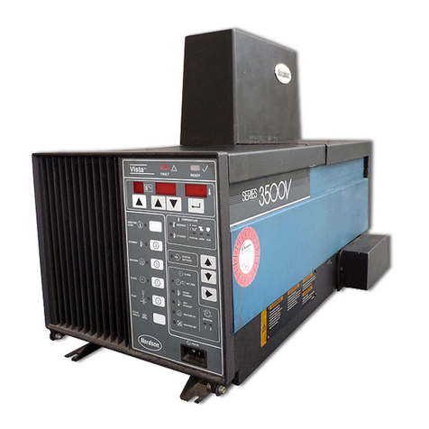
Nordson 3100 User manual

E2000 Nordson Corporation
All rights reserved 41-3000
Issued 11/00 A2EN-02-[3-OVER]–2
Part A, Section 2
Overview
This section covers the following unit configurations.
Model 3100
Voltage All
Pump AC Gear (k or L)
Manifold 2-Port (J)
Control All

Overview
A 2-0
E2000 Nordson Corporation
All rights reserved
41-3000
Issued 11/00
A2EN-02-[3-OVER]–2

4131132A
23
4
1
5
Overview A 2-1
E2000 Nordson Corporation
All rights reserved 41-3000
Issued 11/00 A2EN-02-[3-OVER]–2
Section A 2
Overview
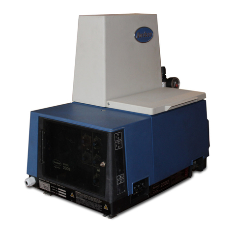
The Series 3100 melter is the main component of the hot melt system.
The melter liquefies the adhesive, maintains it at the setpoint (operating)
temperatures, and pumps it through hoses to dispensing guns. The guns
apply the adhesive to the surface of the product or package. The guns
may be automatically operated, by an air supply or an electric gun driver,
or hand-operated. Most automatic gun systems also use a timer, pattern
controller, or programmable logic controller (PLC) to trigger the guns.
Figure A 2-1 shows a typical Series 3100 hot melt system.
The tank, hoses, and guns are electrically heated: the tank by a cast-in
heater element, the hoses by a spirally wound heating element, and the
guns by a cartridge heater. The temperatures of the tank, hoses, and
guns are individually monitored and controlled using a
temperature-sensing device called a resistance temperature
detector (RTD).
Series 3100 melters can be used to melt and pump almost any
thermoplastic adhesive or similar material that can be liquified and
extruded at temperatures below 218 _C (425 _F). The melters are not
intended for use with polyurethane-reactive (PUR) adhesives because
these adhesives require unique systems designed to prevent curing of
the adhesive inside the dispensing equipment. Series 3100 melters
should be used only as described in this manual.
Fig. A 2-1 3100 Series Hot Melt
System
1. Melter
2. Control panel
3. Hose
4. Air-operated gun
5. Timer, pattern controller, or gun
driver
1. Introduction

Overview
A 2-2
E2000 Nordson Corporation
All rights reserved
41-3000
Issued 11/00
A2EN-02-[3-OVER]–2
The melter has three basic modes of operation: startup, operating, and
standby. Each heated component (each hose, each gun, and the tank) is
referred to as a zone.
There are two types of startup mode: cold startup and warm startup.
Cold Startup
When the melter is turned on, the control system checks the temperature
of all zones. If the controller detects that the temperature of any zone
that is turned on is more than 19 °C (35 °F) below its setpoint
temperature, the melter will perform a cold startup. First the tank and
hoses begin to heat. When the temperature of the tank and the hoses is
within 19 °C (35 °F) of the setpoint temperature, the guns begin to heat.
When all zones are within 3 °C(5°F) of their setpoint temperatures, a
time delay begins. The time delay provides additional time for the
adhesive in the tank to melt. The default time delay setting for gear
pump melters is 46 minutes. At the end of the time delay, the green
SYSTEM READY light turns on to indicate that the system is ready for
operation and the parent machine interlock (PMI) (if used) is enabled.
Warm Startup
When the melter is turned on, the control system checks the temperature
of all zones. If the temperature of all zones that are turned on is within
19 °C (35 °F) of the setpoint temperature, the melter performs a warm
startup. Steady power is applied to each zone until the tank, hoses, and
guns are within 3 °C (5 °F) of their setpoint temperatures. When this
occurs, the green SYSTEM READY light turns on to indicate that the
system is ready for operation and the PMI (if used) is enabled. There is
no time delay during a warm startup.
When a gun is triggered, the pump draws in the melted adhesive and
pushes it through a manifold, filter, and hose to a dispensing gun. The
gun applies the adhesive to the product or package surface.
Figure A 2-2 shows the path that melted adhesive follows as it flows
through the system.
2. Functional Operation
Startup Mode
Operating Mode
Overview A 2-3
E2000 Nordson Corporation
All rights reserved 41-3000
Issued 11/00 A2EN-02-[3-OVER]–2
If the melter has the temperature setback and monitoring feature, the
temperature of all heated zones can be reduced during periods when
normal operation must be interrupted for several hours. When the
setback feature is activated, the controller reduces the temperature of all
zones below their operating temperature setpoints by the value selected
on the temperature setback control dial.
4130777A
1
2
3
4
5
6
7
8
9
10
Fig. A 2-2 Adhesive Flow Path of a Typical Gear Pump System
1. Typical motor
2. Tank
3. Gear pump
4. Pressure relief valve
5. Manifold
6. Filter
7. Gun
8. Hose
9. Drain valve
10. Pressure control valve
Standby Mode
4131133A
1
2
3
4
4131145A
1
2
Overview
A 2-4
E2000 Nordson Corporation
All rights reserved
41-3000
Issued 11/00
A2EN-02-[3-OVER]–2
The major mechanical components of a Series 3100 melter are the tank,
the pump, and the manifold.
The tank holds a large supply of adhesive and melts it before it is
pumped to the hoses and guns. Series 3100 melters have a tank only.
The term “tank” is used to mean the tank strainer, and the melting fins
collectively, including the location of the tank and grid heater connectors.
See Figure A 2-3.
Refer to the Technical Data section for the tank storage capacity and
other key information about the tank.
Fig. A 2-3 Key Parts of the Tank
1. Tank
2. Tank strainer
3. Melting fins
4. Heater connectors
The pump delivers the melted adhesive from the tank through the
manifold and hoses to the guns. The key parts of an AC gear pump are
the gear pump and the AC gear motor. Figure A 2-4 shows the key parts
of the pump.
Refer to the Technical Data section for the pump delivery rate and other
key information about the pump.
Fig. A 2-4 Key Parts of the AC Gear
Pump
1. AC gear motor
2. Gear pump
3. Overview of the
Mechanical Components
Tank
Pump

Overview A 2-5
E2000 Nordson Corporation
All rights reserved 41-3000
Issued 11/00 A2EN-02-[3-OVER]–2
The manifold directs the flow of adhesive from the pump through the
manifold filter to the hoses. The manifold can be non-circulating,
internally circulating, or externally circulating. The manifold components
vary depending on the configuration of the melter. All manifolds have the
following components:
Sa manifold filter (standard or reverse-flush)
Sa pressure relief valve
Sa drain valve (the reverse-flush filter has two drain valves)
Sports for up to four or six hoses
Figure A 2-5 shows several different manifolds and their components.
41310004A
ÏÏÏ
ÏÏÏ
ÏÏÏ
ÌÌ
ÌÌ
2
3
4
1
5
3
4
11
4
3
2
678
Fig. A 2-5 Key Parts of the Manifold
1. Pressure relief valve
2. Standard manifold filter
3. Drain valve
4. Hose ports
5. Reverse-flush filter
6. Pressure control valve
7. Circulation control valve
8. Air-piloted pressure control valve
Manifold

Overview
A 2-6
E2000 Nordson Corporation
All rights reserved
41-3000
Issued 11/00
A2EN-02-[3-OVER]–2
See Figure A 2-6. The MicroSet control system determines how the
melter functions and the temperatures at which the heated zones
operate. The melter will have the MultiScan version of the MicroSet
control system.
NOTE: The Installation section provides detailed procedures for
customizing the control system, and the Operation section provides
detailed procedures for operating and monitoring the control panel.
4131146A
Fig. A 2-6 MultiScan Control Panel
4. Overview of the Control
System

Overview A 2-7
E2000 Nordson Corporation
All rights reserved 41-3000
Issued 11/00 A2EN-02-[3-OVER]–2
All MultiScan melters have the following functions.
Temperature Control Faults
If an RTD circuit is open or shorted or if the temperature of one of the
heated zones reaches a preset overtemperature setpoint, the melter will
indicate a fault and a two-minute time delay will begin. If the fault is not
corrected within two minutes, the controller will trip the circuit breaker and
turn power to the melter off. The melter may be turned on again
immediately and will provide another two-minute time delay to correct the
fault. This process can be repeated indefinitely until the fault is corrected
or until the tank temperature exceeds 260 °C (500 °F). When the tank
temperature exceeds 260 °C (500 °F), the tank overtemperature
thermostat will close and immediately trip the circuit breaker to turn
power to the melter off. When this occurs, the melter cannot be turned
back on until the tank temperature falls below 260 °C (500 °F).
Parent Machine Interlock
The PMI can be used to prevent production from running until the system
is fully operational (indicated when the SYSTEM READY light is on). The
PMI is a set of dry contacts on the main control board that close when the
SYSTEM READY light turns on. Connecting the production line start
circuit in series with the PMI contacts will inhibit the production line until
the system is ready.
Fault Output Contacts
The fault output contacts can be used to signal an external device or to
automatically activate or deactivate the device when a fault occurs.
Melters with a MultiScan control system may have one or more of the
following features, depending on the configuration of the melter.
Digital Readout
Melters with a digital readout have a numerical light-emitting diode (LED)
display of the temperature of the heated zones. Temperature can be
displayed in either °C or °F. A STEP/HOLD/SCAN switch is used to set
how the temperatures are displayed.
Standard Functions
MultiScan Optional Features

Overview
A 2-8
E2000 Nordson Corporation
All rights reserved
41-3000
Issued 11/00
A2EN-02-[3-OVER]–2
Temperature Setback and Monitoring Control
Melters with the temperature setback feature allow for the reduction of
the temperature of the heated zones without changing their temperature
setpoints and without shutting the melter down. This feature is especially
useful when normal operation must be temporarily interrupted. The
adhesive in the system stays hot, but at a lower temperature, reducing
char formation.
Melters with the temperature monitoring feature allow the setting of a plus
and minus (overtemperature and undertemperature) band around the
temperature setpoints to provide a warning should any zone temperature
deviate from its setpoint.
Input/Output Board
On melters with an input/output (I/O) board, some of the melter’s
indications and functions can be remotely monitored and controlled.
There are two types of I/O board: one for piston pump melters and one
for gear pump melters.
The gear pump I/O board allows remote monitoring of
Sthe melter on/off status
Sthe temperature setback on/off status
Sthe warning condition status
Sthe motor on/off status
Sthe motor fault warning status
The gear pump I/O board allows the operator to remotely
Sturn the melter on/off (by activating the sleep mode)
Sturn the temperature setback on/off
Sturn the motor on/off
Refer to Input/Output Board in the Options section for more information
about the I/O board.
Electric Line Filter
The electric line filter reduces electrical noise conducted by the input
power source. Refer to Electric Line Filter in the Options section for more
information about the electric line filter.

Overview A 2-9
E2000 Nordson Corporation
All rights reserved 41-3000
Issued 11/00 A2EN-02-[3-OVER]–2
Low-Level Switch
The low-level switch consists of a float device that follows the level of
adhesive in the tank and a mercury switch that closes when the adhesive
level is low. The low-level switch can be connected to a
customer-supplied indicator to indicate when the level of adhesive in the
tank is low. Refer to Low-Level Switch in the Options section for more
information about the low-level switch.
There are two similar, but not identical, configuration codes related to the
Series 3100 melter: the melter configuration code and the manual
configuration code.
SThe melter configuration code appears on the identification plate on
the melter. This code indicates the type of melter and the features of
the melter, and must be provided to Nordson in order to receive
correct service information or parts.
SThe manual configuration code appears on the title page of the
product manual. This code can be used to verify that the manual
received is specific to the melter.
See Figure A 2-7. To determine the type of melter provided and the
features of the melter, find the melter configuration code (UNIT NO.)
printed on the melter. The unit number appears on the identification plate
located above the hose ports. Refer to the following illustration and
tables to interpret the melter configuration code.
5. Explanation of
Configuration Codes
Understanding the Melter
Configuration Code

Overview
A 2-10
E2000 Nordson Corporation
All rights reserved
41-3000
Issued 11/00
A2EN-02-[3-OVER]–2
4130667A
123456
Fig. A 2-7 Location of Melter Configuration Code
Understanding the Melter
Configuration Code (contd.)

Overview A 2-11
E2000 Nordson Corporation
All rights reserved 41-3000
Issued 11/00 A2EN-02-[3-OVER]–2
Model
Pump Manifold
Control
Options
Voltage
Elec. cap.
–/
Model Description Tank Capacity Melt Rate
3100 Series 3100 3.6 kg (8 lb) 3.6 kg/hr (8 lb/hr)
3400 Series 3400 5.4 kg (12 lb) 6.8 kg/hr (15 lb/hr)
3500 Series 3500 8.6 kg (19 lb) 9.5 kg/hr (21 lb/hr)
3700 Series 3700 13.6 kg (30 lb) 18.1 kg/hr (40 lb/hr)
3830 Series 3830 13.6 kg (30 lb) 15.9 kg/hr (35 lb/hr)
3860 Series 3860 31.8 kg (70 lb) 24.9 kg/hr (55 lb/hr)
3890 Series 3890 45.4 kg (100 lb) 24.9 kg/hr (55 lb/hr)
3930 Series 3930 13.6 kg (30 lb) 27.3 kg/hr (60 lb/hr)
3960 Series 3960 31.8 kg (70 lb) 45.5 kg/hr (100 lb/hr)
AG-30 AquaGuard 8.6 kg (19 lb) 9.5 kg/hr (21 lb/hr)
Voltage Description
1200-240 VAC without neutral
2400/230 VAC with neutral
3400 VAC without neutral
Pump Description
E14:1 SP piston pump
F21:1 SP piston pump
G6:1 SP piston pump
KAC gear pump, 200 VAC
LAC gear pump, 230 VAC (when Voltage = 1)
LAC gear pump, 250 VAC (when Voltage = 2)
ODC gear pump, 49 kg/hr (108 lb/hr)
RDC gear pump, 24.5 kg/hr (54 lb/hr)
SDC gear pump, 11 kg/hr (24 lb/hr)
TDC gear pump, 24.5 kg/hr (54 lb/hr)
UDC gear pump, 3.6 kg/hr (8 lb/hr)
WDC gear pump, 1.8 kg/hr (4 lb/hr)

Overview
A 2-12
E2000 Nordson Corporation
All rights reserved
41-3000
Issued 11/00
A2EN-02-[3-OVER]–2
Manifold Description
ANon-circulating, 4-port, piston pump, SF
BNon-circulating, 6-port, piston pump, SF
CNon-circulating, 6-port, piston pump, RFF
FInternal circulating, 4-port, DC gear pump, SF, CV
JInternal circulating, 4-port, AC/DC gear pump, SF, PCV
KInternal circulating, 6-port, DC gear pump, SF, PCV
LInternal circulating, 6-port, DC gear pump, RFF, PCV
OInternal circulating, 6-port, DC gear pump, SF, CV
PInternal circulating, 6-port, DC gear pump, RFF, CV
SExternal circulating, 2-port, piston pump, SF, CV
TExternal circulating, 2-port, piston pump, RFF, CV
UExternal circulating, 2-port, DC gear pump, RFF, PCV
RExternal circulating, 2-port, DC gear pump, SF, PCV
SF = standard filter
RFF = reverse-flush filter
PCV = pressure control valve
CV = circulation control valve
Control Description
1 UniScan
3 MultiScan
Electrical
Capacity Description
22 hoses/2 guns
44 hoses/4 guns
66 hoses/6 guns
Options Description
ALow-level switch
CTemperature setback (MultiScan only)
DDigital temperature display, temperature band monitoring,
and temperature setback (MultiScan only)
EI/O board, piston pump melters (MultiScan only)
FI/O board, gear pump melters (MultiScan only)
KEnglish/Japanese language tags
PPressure dump (motor and pressure control only)
QMotor and pressure control (MultiScan only)
RCE certification
TKey-to-line control (MultiScan only)
UElectric line filter
Understanding the Melter
Configuration Code (contd.)

Overview A 2-13
E2000 Nordson Corporation
All rights reserved 41-3000
Issued 11/00 A2EN-02-[3-OVER]–2
The manual configuration code appears on the cover page of the product
manual. Use the following chart and table to interpret the manual
configuration code.
Model
Pump Manifold
Control Options
Voltage
Elec. cap.
M–X X / X
Model Voltage Pump Manifold Control Electrical
Capacity Options
3100
3400
3500
3700
3830
3860
3890
3930
3960
AG30
X All voltages
(See Note A) E piston pump
F piston pump
G piston pump
K AC gear pump
L AC gear pump
O DC gear pump
R DC gear pump
S DC gear pump
T DC gear pump
U DC gear pump
W DC gear pump
A 4-port
B 6-port
C 6-port
F 4-port
J 4-port
K 6-port
L 6-port
O 6-port
P 6-port
S 2-port
T 2-port
U 2-port
R 2-port
1 UniScan
3 MultiScan
X All elec. cap.
(See Note A)
X All options
(See Note A)
NOTE A: An X is a placeholder in the the manual configuration code used to denote data that is not pertinent to the
manual configuration.
Understanding the Manual
Configuration Code

Overview
A 2-14
E2000 Nordson Corporation
All rights reserved
41-3000
Issued 11/00
A2EN-02-[3-OVER]–2
This manual suits for next models
9
Table of contents
Other Nordson Melting Machine manuals

Nordson
Nordson EP 30 User manual

Nordson
Nordson ProBlue Flex User manual

Nordson
Nordson ProBlue Flex User manual

Nordson
Nordson 3500V Series Parts list manual

Nordson
Nordson AltaBlueA4TP Reference guide

Nordson
Nordson VersaBlue VBN 50 User manual

Nordson
Nordson 3100V Series Reference guide

Nordson
Nordson Mesa Fulfill Reference guide

Nordson
Nordson 3500 Series Parts list manual

Nordson
Nordson ProBlue 1028303 User manual