Nordson 3930 User manual

E2000 Nordson Corporation
All rights reserved 41-3000
Issued 9/00 B3EN-03-[3-TANK]-3
Part B, Section 3
Tank and Manifold
This section covers the following unit configurations.
Model 3930
3960
Voltage 1, 2
Pump Piston (F)
AC gear (K or L)
DC gear (O, R, S, T, U, or W)
Manifold 4-Port (A or J)
6-port (B, C, K, L, O, or P)
2-port (R, U, S, or T)
Control MultiScan (3)

Tank and Manifold
B 3-0
E2000 Nordson Corporation
All rights reserved
41-3000
Issued 9/00
B3EN-03-[3-TANK]-3

Tank and Manifold B 3-1
E2000 Nordson Corporation
All rights reserved 41-3000
Issued 9/00 B3EN-03-[3-TANK]-3
Section B 3
Tank and Manifold
WARNING: Allow only qualified personnel to perform the
following tasks. Follow the safety instructions in this document
and all other related documentation.
This section describes how to disassemble and reassemble the tank and
manifold. It also includes procedures for replacing the pressure relief
valve, drain valve, and, if applicable, the circulation control valve,
pressure control valve, or air-piloted pressure control valve.
Refer to the following sections for additional information on the tank and
manifold:
STechnical Data provides tank specifications, including the tank
capacity, the tank volume, and the dimensions of the tank lid
opening.
SOperation includes the procedure for filling the tank with adhesive.
SMaintenance includes procedures for flushing the tank and
manifold and for draining adhesive from the tank.
SControl System includes procedures for replacing the tank
resistance temperature detector (RTD) or thermostat.
SParts includes illustrated parts lists for the melter and all major
assemblies. Refer to this section for the part number of any
component that needs to be replaced.
1. Introduction

Tank and Manifold
B 3-2
E2000 Nordson Corporation
All rights reserved
41-3000
Issued 9/00
B3EN-03-[3-TANK]-3
Before beginning any tank or manifold repairs, you should be familiar with
the major components of the tank.
The tank holds a supply of adhesive and melts it before it is pumped to
the hoses and guns. The tank is made up of a hopper, grid, and
reservoir. Figure B 3-1 shows the key parts of the tank.
4130644
2
3
4
1
Fig. B 3-1 Key Parts of the Tank (Series 3960 tank shown)
1. Hopper
2. Grid 3. Reservoir
4. Heater connectors
Hopper and Grid
The hopper holds a supply of adhesive. It is supported by the grid, which
connects the hopper to the reservoir. The grid melts the adhesive, which
then falls between blades and into the reservoir below. The grid has a
cast-in heating element. An RTD and overtemperature thermostat sense
the grid temperature and provide input to the control system.
Reservoir
The reservoir maintains the melted adhesive at application temperature
and directs it to the pump inlet. Like the grid, it has a cast-in heater and
an RTD and overtemperature thermostat that sense the tank temperature
and provide input to the control system.
2. Overview of the Tank
Tank

Tank and Manifold B 3-3
E2000 Nordson Corporation
All rights reserved 41-3000
Issued 9/00 B3EN-03-[3-TANK]-3
Because the tank and manifold have no moving parts, you should not
need to replace them. However, if you need to remove them from the
melter for any reason, follow these procedures. Refer to the Parts
section for the part numbers of any components that need to be replaced.
You can use the parts list illustrations as a guide as you perform the
following disassembly and reassembly procedures.
To replace both the tank and manifold, you must complete all of the
following procedures:
SPreparing to Replace the Tank or Manifold
SRemoving the Hopper
SRemoving the Grid
SDisassemlbing the Reservoir and Manifold
SReassembling the Reservoir and Manifold
SInstalling the Grid
SInstalling the Hopper
SRestoring the Melter to Normal Operation
These instructions can also be used to replace just one part of the tank
assembly.
Complete this procedure before you perform any tank repairs.
1. Heat the melter to operating temperature to aid disassembly and to
prepare for draining as much adhesive as possible from the tank.
2. Drain the tank. For information about different ways to drain the tank,
refer to Cleaning the System in the Maintenance section.
3. Piston pump and MPC melters: Turn the pump air pressure
regulator to 0; then disconnect the air regulator from the melter.
4. Remove the pump from the melter. Refer to the Pump section for the
pump removal procedure.
5. Turn off the melter; disconnect and lock out electrical power to the
melter at the branch circuit disconnect switch, and disconnect and
lock out electrical power supplied through any I/O wiring.
3. Tank and Manifold
Replacement
Preparing to Replace the Tank
or Manifold

Tank and Manifold
B 3-4
E2000 Nordson Corporation
All rights reserved
41-3000
Issued 9/00
B3EN-03-[3-TANK]-3
Follow this procedure to remove the hopper from the melter.
1. If you have not already done so, complete Preparing to Replace the
Tank or Manifold.
2. Carefully remove all insulation from the hopper.
3. See Figure B 3-2. Remove the screws, nuts, washers, and lock
washers that attach the hopper (1) to the grid (3).
4. Carefully separate the hopper from the grid and set it aside.
5. Remove the O-ring (2) from the groove in the grid and discard it. You
should replace the O-ring any time the hopper is removed from the
grid. Refer to the Parts section for the O-ring part number.
4130711A
1
2
3
Fig. B 3-2 Removing the Hopper from the Grid
1. Hopper
2. O-ring 3. Grid
6. Check the gasket on top of the hopper. If it is not damaged, you do
not need to replace it.
Removing the Hopper

Tank and Manifold B 3-5
E2000 Nordson Corporation
All rights reserved 41-3000
Issued 9/00 B3EN-03-[3-TANK]-3
Follow this procedure to remove the grid.
1. Remove the melter’s front and back panels. To do so, you will need
to
Sremove the electrical enclosure lid
Sdisconnect any ground wires
2. Piston pump and MPC melters: See Figure B 3-3. Remove the
screws (2) that hold the air-line adapter (3) to the hose-end panel (1).
4130816
12
2
3
Fig. B 3-3 Removing the Air Line Adapter Screws
1. Hose-end panel
2. Screws 3. Air-line adapter
3. Remove the screws that attach the center front support bracket to the
left and right support brackets. Remove the center front support
bracket and then remove the left and right support brackets.
4. Remove the screws on the bottom of the hose-end panel. Swing the
panel and wire harness away from the melter.
Removing the Grid

Tank and Manifold
B 3-6
E2000 Nordson Corporation
All rights reserved
41-3000
Issued 9/00
B3EN-03-[3-TANK]-3
5. See Figure B 3-4. Remove the RTD, thermostat, and ground wire
from the grid.
4130929A
ÎÎÎÎ
ÎÎÎÎ
ÎÎÎÎ
ÎÎÎÎ
ÏÏÏÏÏ
ÏÏÏÏÏ
ÏÏÏÏÏ
ÏÏÏÏÏ
ÎÎÎÎÎ
ÎÎÎÎÎ
ÎÎÎÎÎ
ÎÎÎÎÎ
ÎÎ
ÎÎ
ÎÎÎÎÎ
ÎÎÎÎÎ
ÎÎÎÎÎ
ÎÎÎÎÎ
2
1
Fig. B 3-4 Removing an RTD and Thermostat (typical)
1. RTD 2. Retainer plate
6. Carefully remove the insulation from the grid.
7. Remove the screws, nuts, washers, and lock washers that attach the
grid to the reservoir.
8. Carefully separate the grid from the reservoir and set it aside.
9. Remove the grid insulator from the reservoir and set it aside.
Follow this procedure to remove the reservoir and manifold and to
disassemble them.
1. If the melter is attached to a support platform, remove any anchoring
bolts.
2. See Figure B 3-4. Remove the RTD, thermostat, and ground wire (if
present) from the tank.
3. Tilt the melter back at an angle to gain access to the base and
remove the screws and washers that attach the manifold to the base.
Return the melter to the level position.
NOTE: Ask an assistant to help you tilt the melter and support it while
you remove the screws and washers.
Removing the Grid (contd.)
Disassembling the Reservoir
and Manifold

Tank and Manifold B 3-7
E2000 Nordson Corporation
All rights reserved 41-3000
Issued 9/00 B3EN-03-[3-TANK]-3
4. Pull the tank and manifold away from the melter. The spacers
between the manifold and the base may come loose at this time. If
they do not, remove them by hand.
5. Disconnect the tank heater wires.
6. Carefully remove all insulation.
7. Remove the screws and washers that secure the manifold to the tank;
then separate the manifold from the tank.
8. Remove the two O-rings from the grooves in the manifold and discard
them. You should replace the O-rings any time the manifold is
separated from the tank. Refer to the Parts section for the O-ring part
number.
Follow this procedure to reassemble the reservoir and manifold and to
reinstall them on the melter.
1. Turn the reservoir upside down and place it on a flat surface.
2. See Figure B 3-5. Lubricate two new O-rings with O-ring lubricant
and place the O-rings in their grooves on the manifold.
4130830A
Fig. B 3-5 Installing New O-rings
3. Turn the manifold upside down and align it correctly on the reservoir.
NOTE: If the O-rings are lubricated, they will stay in the grooves
when you turn the manifold upside down.
Reassembling the Reservoir
and Manifold

Tank and Manifold
B 3-8
E2000 Nordson Corporation
All rights reserved
41-3000
Issued 9/00
B3EN-03-[3-TANK]-3
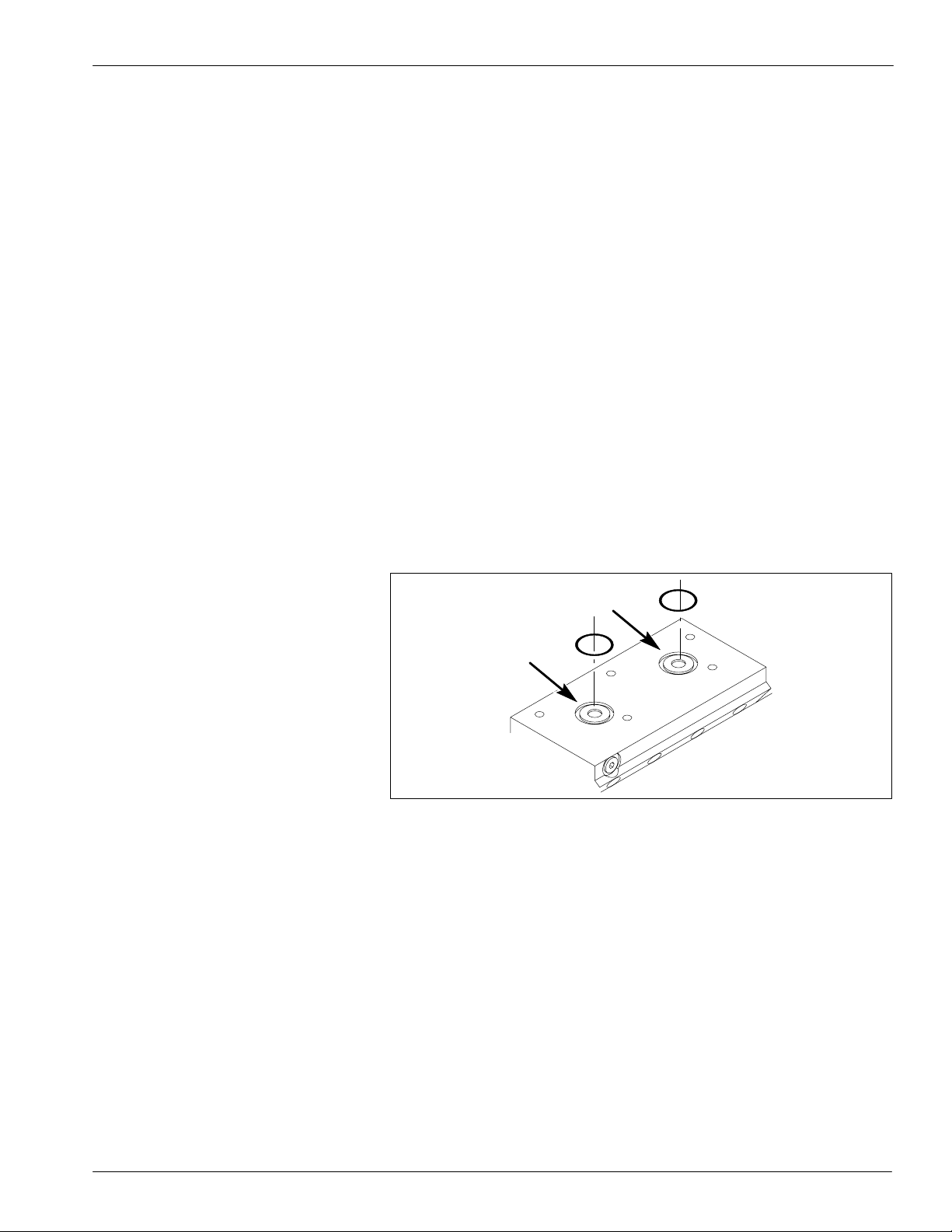
4. Insert the manifold washers and screws in the bottom of the manifold
and tighten them finger tight only. Then tighten the screws in the
sequence shown in Figure B 3-6. Tighten the screws to
5.4–6.8 NSm(4–5 ft-lb).
4130604A
1
2
3
4
5
Fig. B 3-6 Correct Sequence for Tightening Manifold Screws
5. Turn the reservoir and manifold over so that the reservoir’s open side
is up and wrap the insulation around the reservoir and manifold. Use
high-temperature duct tape to secure the insulation.
6. Reconnect the heater wires to the reservoir heater connections.
7. Hold the spacers in place and attach the reservoir and manifold to the
base of the melter with the screws and washers removed earlier. It
may be necessary to tilt the melter to gain access to the bottom of the
base. Tighten the screws to 10.9–13.6 NSm (8–10 ft-lb).
NOTE: Be sure you do not pinch the heater wires when you are
securing the reservoir and manifold to the base.
NOTE: To ease assembly, you can cut the heads off of four M8
screws that are longer than the spacers (do not use the screws
supplied with the service kit). Loosely thread the cut screws into the
tapped holes in the bottom of the manifold. Slip the spacers over the
screws. This will keep the spacers in line until you are ready to install
the supplied screws. When you are ready to install the supplied
screws, remove the cut screws. Ask an assistant to help you tilt the
melter and support it while you replace the screws and washers.
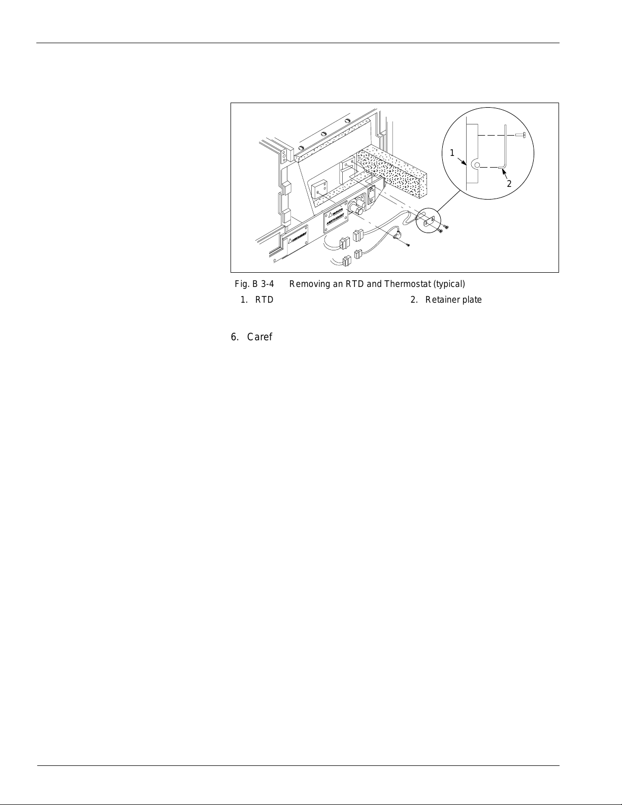
8. Apply thermal compound to the RTD and thermostat and install them
on the side of the reservoir. Make sure the RTD retainer plate is
installed as shown in Figure B 3-4.
9. Reconnect the ground wire (if present) to the reservoir.
10. If the melter was attached to a support platform, anchor it to the
platform now.
Reassembling the Reservoir
and Manifold (contd.)

Tank and Manifold B 3-9
E2000 Nordson Corporation
All rights reserved 41-3000
Issued 9/00 B3EN-03-[3-TANK]-3
Use this procedure to install the grid on the reservoir.
1. Place the grid insulator on top of the reservoir and align the insulator
and reservoir screw holes.
2. Carefully place the grid on the reservoir so that the alignment pins
and screw holes are correctly aligned.
3. Secure the grid to the reservoir with the screws, washers, and lock
washers you removed earlier. Tighten the screws to
5.4–6.8 N•m(4–5 lb-ft).
4. Apply thermal compound to the grid RTD and thermostat and install
them on the side of the grid. Make sure the RTD retainer plate is
installed as shown in Figure B 3-4.
5. Install the insulation on the grid. Use high-temperature duct tape to
secure the insulation.
6. Swing the hose-end panel (with its attached wiring harnesses) into
place on the melter. Make sure the wiring harnesses are properly
routed between the front panel and the insulation. If you removed a
wire channel during the disassembly procedure, replace it now, and
replace any wire ties that you cut. Then secure the panel with the two
screws that fasten the bottom of the panel to the frame.
7. Reattach the left, right, and center support brackets.
8. Make sure the air-line adapter is securely inserted in the recessed
area on the inside of the hose-end panel. Secure the adapter with
the screws you removed earlier.
9. Attach the ground wire to the rear panel of the melter. Slide the panel
into place and secure it with the captive screws.
10. Lubricate a new O-ring with O-ring lubricant and place it in the groove
on top of the grid.
Installing the Grid

Tank and Manifold
B 3-10
E2000 Nordson Corporation
All rights reserved
41-3000
Issued 9/00
B3EN-03-[3-TANK]-3
Follow this procedure to install the hopper.
1. Place the hopper on the grid and align the screw holes. Secure it
with the screws, washers, and lock washers you removed earlier.
Tighten the screws to 4.1–5.4 N•m (3–4 ft-lb).
2. Install the insulation on the hopper. Use high-temperature duct tape
to secure the insulation.
3. Attach the ground wire to the front panel. Slide the panel into place
and secure it with the captive screws.
4. Attach the ground wire to the rear panel of the melter. Slide the panel
into place and secure it with the captive screws.
Follow this procedure to reinstall the pump and restore the melter to
normal operation.
1. Install the pump. Refer to the Pump section for the pump installation
procedure.
2. Install and secure the pump cover.
3. Piston pump and MPC melters: Return the pump air pressure to
the normal operating setting.
4. Remove the lock-out and restore power to the melter.
Installing the Hopper
Restoring the Melter to Normal
Operation

Tank and Manifold B 3-11
E2000 Nordson Corporation
All rights reserved 41-3000
Issued 9/00 B3EN-03-[3-TANK]-3
Use these procedures to replace the pressure relief valve, drain valve, or
other manifold valves as applicable.
Follow this procedure to replace the pressure relief valve. The pressure
relief valve is installed in the bottom of the tank.
1. Drain as much adhesive from the tank as possible. Refer to Cleaning
the System in the Maintenance section for different ways to drain the
tank.
2. See Figure B 3-7. Use a socket wrench to loosen the pressure relief
valve; then carefully unscrew the valve and remove it.
3. Screw the new valve into the tank until it is finger-tight.
4. Use a socket wrench to tighten the valve. Tighten to
14–16 NSm (10–12 ft-lb).
5. Refill the tank with adhesive and resume normal operation.
4130835
1
2
Fig. B 3-7 Replacing the Pressure Control Valve (typical)
1. Pressure control valve 2. Tank
4. Valve Replacement
Procedures
Replacing the Pressure Relief
Valve

Tank and Manifold
B 3-12
E2000 Nordson Corporation
All rights reserved
41-3000
Issued 9/00
B3EN-03-[3-TANK]-3
Follow this procedure to replace the drain valve. Your melter may have
one or two drain valves. A standard manifold filter has one drain valve,
and a reverse-flush manifold filter has two drain valves. Refer to the
manifold parts list illustration in the Parts section as necessary as you
perform this procedure.
1. Make sure the melter is at operating temperature.
2. Relieve hydraulic pressure. Refer to Relieving Hydraulic Pressure in
the Maintenance section.
3. See Figure B 3-8. Remove the drain valve alignment screw (1) and
washer (2); then remove the valve (3) from the melter. Some
adhesive will flow from the valve.
4. Screw the new drain valve into the manifold until it is secure; then
adjust it as necessary to install and tighten the alignment screw and
washer.
5. Resume normal operation.
4130836
123
Fig. B 3-8 Drain Valve Components
1. Alignment screw
2. Washer 3. Drain valve
Replacing the Drain Valve

Tank and Manifold B 3-13
E2000 Nordson Corporation
All rights reserved 41-3000
Issued 9/00 B3EN-03-[3-TANK]-3
Depending on the configuration of your melter, the manifold may include
a circulation control valve, pressure control valve, or air-piloted pressure
control valve. Follow this procedure to replace any of these valves.
Refer to the manifold parts list illustration in the Parts section as
necessary as you perform this procedure.
1. Make sure the melter is at operating temperature.
2. Turn off the melter; disconnect and lock out electrical power to the
melter at the branch circuit disconnect switch, and disconnect and
lock out electrical power supplied through any I/O wiring.
3. Relieve hydraulic pressure. Refer to Relieving Hydraulic Pressure in
the Maintenance section.
4. If applicable, shut off and lock out the air supply to the melter.
5. Air-piloted pressure control valve: Disconnect the air line from the
air-piloted pressure control valve.
6. See Figure B 3-9. Unscrew the valve (1, 2, or 3) from the manifold.
Some adhesive will flow from the manifold when the valve is
removed.
7. Install the new valve and a new O-ring. The O-ring must be replaced
any time the valve is removed.
8. Restore air and power to the melter and resume normal operation.
4105077A
1
23
Fig. B 3-9 Replacing Other Manifold Valves
1. Circulation control valve
2. Pressure control valve 3. Air-piloted pressure control
valve
Replacing Other Manifold
Valves

Tank and Manifold
B 3-14
E2000 Nordson Corporation
All rights reserved
41-3000
Issued 9/00
B3EN-03-[3-TANK]-3
This manual suits for next models
1
Table of contents
Other Nordson Melting Machine manuals

Nordson
Nordson 3500V Series Parts list manual

Nordson
Nordson DuraDrum User manual

Nordson
Nordson Mesa Fulfill Reference guide

Nordson
Nordson VersaBlue VBN 50 User manual

Nordson
Nordson ProBlue 1028303 User manual

Nordson
Nordson 3500 Series Parts list manual

Nordson
Nordson ProBlue Flex User manual

Nordson
Nordson 3100 User manual

Nordson
Nordson ProBlue Flex User manual

Nordson
Nordson 3100V Series Reference guide