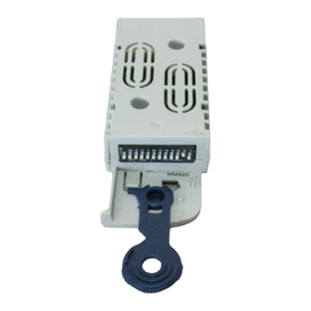
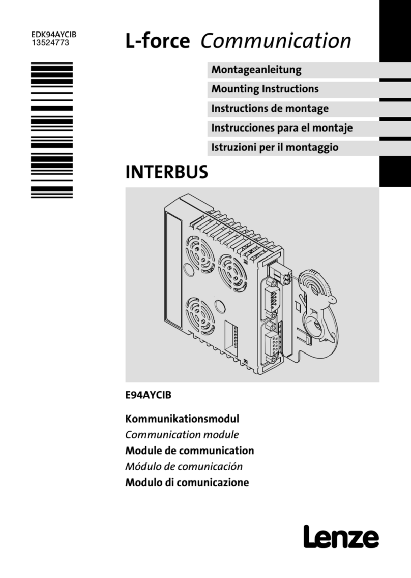
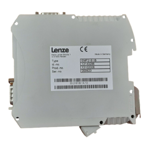
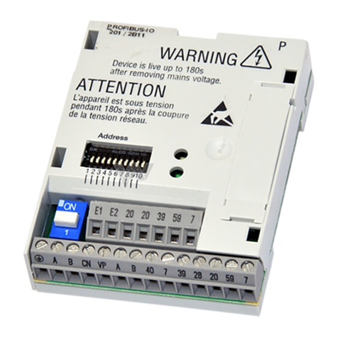
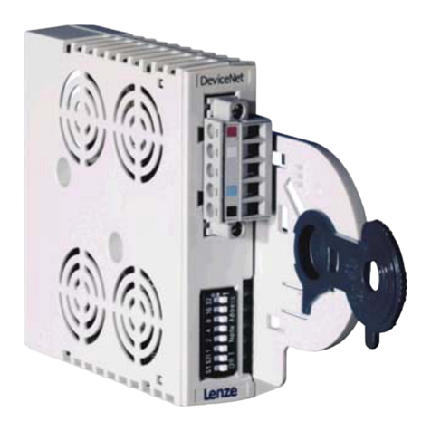
Lenze E82ZAFIC010 User manual

EDK82ZAFIC−010 DE/EN/FR 4.036
legende_kopfzeile−DUMMY_NUM_Reset
Legend for fold−out page
Pos. Description Detailed
information
Status of the INTERBUS communication (yellow) 66
Connection status to the drive controller (green)
DIP switch S1
lSetting for the last node = OFF
lSetting for all other nodes = ON
64
DIP switches S2 ... S4
lConfiguration of
– the process data words (PCD)
– the parameter data words (PCP)
– the ID code
63
Plug connector X3.1
lConnection for external voltage supply of the function module
48
Plug connector X3.2
lReference terminal GND1, e.g. for external voltage supply of the function
module
lReference terminal GND2, e.g. for external supply of the controller inhibit
(CINH)
Plug connector X3.3
lConnection for
– INTERBUS
– controller inhibit (CINH)
– internal supply of the controller inhibit (CINH)
Nameplate 45
0Fig. 0Tab. 0

Contents i
EDK82ZAFIC−010 DE/EN/FR 4.0 37
Inhalt
1 About this documentation 38. . . . . . . . . . . . . . . . . . . . . . . . . . . . . . . . . . . . . . . . . . .
Conventions used 39. . . . . . . . . . . . . . . . . . . . . . . . . . . . . . . . . . . . . . . . . . . . . . . . . .
Notes used 40. . . . . . . . . . . . . . . . . . . . . . . . . . . . . . . . . . . . . . . . . . . . . . . . . . . . . . . .
2 Safety instructions 42. . . . . . . . . . . . . . . . . . . . . . . . . . . . . . . . . . . . . . . . . . . . . . . . .
3 Product description 43. . . . . . . . . . . . . . . . . . . . . . . . . . . . . . . . . . . . . . . . . . . . . . . . .
Function 43. . . . . . . . . . . . . . . . . . . . . . . . . . . . . . . . . . . . . . . . . . . . . . . . . . . . . . . . .
Application as directed 43. . . . . . . . . . . . . . . . . . . . . . . . . . . . . . . . . . . . . . . . . . . . . .
Scope of supply 44. . . . . . . . . . . . . . . . . . . . . . . . . . . . . . . . . . . . . . . . . . . . . . . . . . . .
Identification 45. . . . . . . . . . . . . . . . . . . . . . . . . . . . . . . . . . . . . . . . . . . . . . . . . . . . . .
4 Technical data 46. . . . . . . . . . . . . . . . . . . . . . . . . . . . . . . . . . . . . . . . . . . . . . . . . . . . .
General Data 46. . . . . . . . . . . . . . . . . . . . . . . . . . . . . . . . . . . . . . . . . . . . . . . . . . . . . .
Operating conditions 47. . . . . . . . . . . . . . . . . . . . . . . . . . . . . . . . . . . . . . . . . . . . . . .
Protective insulation 47. . . . . . . . . . . . . . . . . . . . . . . . . . . . . . . . . . . . . . . . . . . . . . . .
Connection terminals 48. . . . . . . . . . . . . . . . . . . . . . . . . . . . . . . . . . . . . . . . . . . . . .
Dimensions 49. . . . . . . . . . . . . . . . . . . . . . . . . . . . . . . . . . . . . . . . . . . . . . . . . . . . . . .
5 Mechanical installation 50. . . . . . . . . . . . . . . . . . . . . . . . . . . . . . . . . . . . . . . . . . . . .
6 Electrical installation 51. . . . . . . . . . . . . . . . . . . . . . . . . . . . . . . . . . . . . . . . . . . . . . .
Use of plug connectors 51. . . . . . . . . . . . . . . . . . . . . . . . . . . . . . . . . . . . . . . . . . . . . .
Wiring according to EMC 52. . . . . . . . . . . . . . . . . . . . . . . . . . . . . . . . . . . . . . . . . . . .
Wiring to a host 53. . . . . . . . . . . . . . . . . . . . . . . . . . . . . . . . . . . . . . . . . . . . . . . . . . . .
Voltage supply 55. . . . . . . . . . . . . . . . . . . . . . . . . . . . . . . . . . . . . . . . . . . . . . . . . . . . .
Terminal assignment 57. . . . . . . . . . . . . . . . . . . . . . . . . . . . . . . . . . . . . . . . . . . . . . .
Cable cross−sections and screw−tightening torques 58. . . . . . . . . . . . . . . . . . . . . . .
7 Commissioning 59. . . . . . . . . . . . . . . . . . . . . . . . . . . . . . . . . . . . . . . . . . . . . . . . . . . .
Before switching on 59. . . . . . . . . . . . . . . . . . . . . . . . . . . . . . . . . . . . . . . . . . . . . . . .
Commissioning steps 60. . . . . . . . . . . . . . . . . . . . . . . . . . . . . . . . . . . . . . . . . . . . . . .
Control system configuration 62. . . . . . . . . . . . . . . . . . . . . . . . . . . . . . . . . . . . . . . .
Defining the user data length 63. . . . . . . . . . . . . . . . . . . . . . . . . . . . . . . . . . . . . . . .
Setting for last bus node 64. . . . . . . . . . . . . . . . . . . . . . . . . . . . . . . . . . . . . . . . . . . . .
Connecting the mains voltage 65. . . . . . . . . . . . . . . . . . . . . . . . . . . . . . . . . . . . . . . .
8 Diagnostics 66. . . . . . . . . . . . . . . . . . . . . . . . . . . . . . . . . . . . . . . . . . . . . . . . . . . . . . .
LED status displays 66. . . . . . . . . . . . . . . . . . . . . . . . . . . . . . . . . . . . . . . . . . . . . . . . .
1 About this documentation
EDK82ZAFIC−010 DE/EN/FR 4.038
H1_Über_die_Doku−TIP_download
1 About this documentation
Contents
This documentation includes ...
ƒ Information about the mechanical and electrical installation of the function module;
ƒ Information about the commissioning of the function module;
ƒ Safety instructions which you must observe in any case;
ƒ Data about the versions of Lenze standard devices to be used;
ƒ Technical data.
Validity information
The information given in this documentation is valid for the following devices:
Function module Type designation From hardware version From software version
INTERBUS PT E82ZAFIC010 4A 20
Target group
This documentation is directed at persons who install and commission the described
product according to the project requirements.
Tip!
Documentation and software updates for further Lenze products can be found
on the Internet in the "Services & Downloads" area under
http://www.Lenze.com

About this documentation
Conventions used
1
EDK82ZAFIC−010 DE/EN/FR 4.0 39
H2_Verw_Konventionen−Verw_Konv_MA_KommModule
Conventions used
This documentation uses the following conventions to distinguish between different types
of information:
Type of information Identification Examples/notes
Numbers
Decimal separator Point The decimal point is used throughout
this documentation.
Example: 1234.56
Symbols
Page reference Reference to another page with
additional information
Example: 16 = see page 16

1 About this documentation
Notes used
EDK82ZAFIC−010 DE/EN/FR 4.040
H2_Def_Hinweise−SIC_pikt_EN
Notes used
The following pictographs and signal words are used in this documentation to indicate
dangers and important information:
Safety instructions
Structure of safety instructions:
Danger!
(characterises the type and severity of danger)
Note
(describes the danger and gives information about how to prevent dangerous
situations)
Pictograph and signal word Meaning
Danger!
Danger of personal injury through dangerous electrical
voltage.
Reference to an imminent danger that may result in
death or serious personal injury if the corresponding
measures are not taken.
Danger!
Danger of personal injury through a general source of
danger.
Reference to an imminent danger that may result in
death or serious personal injury if the corresponding
measures are not taken.
Stop!
Danger of property damage.
Reference to a possible danger that may result in
property damage if the corresponding measures are not
taken.

2 Safety instructions
EDK82ZAFIC−010 DE/EN/FR 4.042
H1sic_EN−stop_statEntlad_FktModule
2 Safety instructions
Danger!
Inappropriate handling of the function module and the standard device can
cause serious injuries to persons and damage to material assets.
Observe the safety instructions and residual hazards included in the
documentation of the standard device.
Stop!
Electrostatic discharge
Electronic components within the function module can be damaged or
destroyed by electrostatic discharge.
Possible consequences:
ƒThe function module is defective.
Protective measures
ƒFree yourself from any electrostatic charge before you touch the module.

Product description
Function
3
EDK82ZAFIC−010 DE/EN/FR 4.0 43
−H1−TIP zu KHB
3 Product description
Function
The function module connects the standard device to the INTERBUS communication
system.
Application as directed
The function module ...
ƒ is an accessory module for use in conjunction with the following Lenze standard
devices:
Product series Device name From hardware version
Frequency inverter 8200 vector Vx14
ƒ is a device intended for use in industrial power systems.
Any other use shall be deemed inappropriate!
Tip!
More information about this function module is available in the corresponding
communication manual.
The PDF file can be downloaded from the Internet in the "Services &
Downloads" area at
http://www.Lenze.com

3 Product description
Scope of supply
EDK82ZAFIC−010 DE/EN/FR 4.0
44
H2_Lieferumf−Liefumfang E82ZAFIC010_Tab
Scope of supply
E82ZAFI014B, AFX006/007/011/012
Pos. Scope of supply
Function module E82ZAFIC010
Mounting Instructions
/ 2 plug connectors with spring connection, 3−pole
Plug connector with spring connection, 13−pole
Mounting Instructions

Product description
Identification
3
EDK82ZAFIC−010 DE/EN/FR 4.0 45
H2_Identifikation−Typschluessel_E82ZAFIC010
Identification
E82AF000P0B201XX
APPLICATION
010 / 3A22
A22A22
APPLICATION
010 / 3A22
L
Type
Id.-No.
Prod.-No.
Ser.-No.
E82ZAFX005
E82ZAF I C 010 4A 20
Product series
INTERBUS
Version
Variant: PT (plug terminal) with spring
connection
Hardware version
Software version

4 Technical data
General Data
EDK82ZAFIC−010 DE/EN/FR 4.046
H1_Daten−Komm_Daten_E82ZAFICxxx
4 Technical data
General Data
Area Values
Order designation E82TAFIC010
Communication medium RS485
Network topology Ring (go and return line in the same cable)
Number of bus nodes Dependent on INTERBUS master (e.g. Phoenix Contact G4 master).
For the following data, which depend on whether PCP
communication is used or not, always the smaller value applies:
lwith PCP communication: max. 62 or
lwithout PCP communication: max. 256/number of PCDs
Distance between two bus
nodes Max. 400 m
INTERBUS identification
(ID code)
lWith 1 word PCP: 227 (0xE3)
lWithout PCP: 3 (0x03)
Drive profile DRIVECOM profile "Drive technology 20"
INTERBUS node Slave
Baud rate 500 kbps
Process data words (PCD),
16 bits 1 ... 4 words
Parameter data words (PCP),
16 bits 0 or 1 word
PDU length Max. 64 bytes
Supported PCP services lInitiate
lAbort
lStatus
lIdentify
lGet−0V−long
lRead
lWrite
Communication time lSum of the cycle time and the processing time in the bus nodes.
The times are independent of each other.
lProcessing time in the standard device
– Parameter data (PCP): approx. 30 ms + 20 ms tolerance
– Process data (PCD): approx. 3 ms + 2 ms tolerance

Technical data
Operating conditions
4
EDK82ZAFIC−010 DE/EN/FR 4.0 47
−H2−Schutzisolierung
Operating conditions
Ambient conditions
Climate
Storage IEC/EN 60721−3−1 1K3 (−25 to +60 °C)
Transport IEC/EN 60721−3−2 2K3 (−25 to +70 °C)
Operation Corresponding to the data of the Lenze standard device used (see
documentation of the standard device).
Pollution EN 61800−5−1 Degree of pollution 2
Degree of protection IP20 (protection against accidental contact according to NEMA 250 type 1)
Protective insulation
Insulation between incoming bus and ... Type of insulation (to EN 61800−5−1)
l8200 vector/motec power section Reinforced insulation
lReference earth / PE Functional insulation
lTerminal X3.1/59 Functional insulation
lTerminal X3.3/20 Functional insulation
lTerminal X3.3/28 Functional insulation
Insulation between incoming bus and ... Type of insulation (to EN 61800−5−1)
Outgoing bus Functional insulation
Insulation between outgoing bus and ... Type of insulation (to EN 61800−5−1)
l8200 vector/motec power section Reinforced insulation
lReference earth / PE Functional insulation
lTerminal X3.1/59 No electrical isolation
lTerminal X3.3/20 No electrical isolation
lTerminal X3.3/28 Functional insulation

4 Technical data
Connection terminals
EDK82ZAFIC−010 DE/EN/FR 4.048
H2 DatenAnschlKlemmen−INS_Klembesch
Connection terminals
Terminal
X3.1/
Designation Function / level
59 External voltage supply of the function module
lU = 24 V DC (21.6 V − 0% ... 26.4 V + 0 %)
lCurrent consumption for 24 V DC: I = 90 mA
If the supply voltage is looped through to other bus nodes via
terminal 59, the current flowing must not exceed 3 A.
7 GND1 Reference potential for terminal X3.3/20
Terminal
X3.2/
Designation Function / level
7 GND1 Reference potential for terminal X3.3/20
39 GND2 Reference potential for controller inhibit (CINH) on terminal X3.3/28
Terminal
X3.3/
Designation Function / level
A /DO1
RS485 data line (incoming)
B DO1
C /DI1
D DI1
E GND3 Reference potential for incoming data line
F /DO2
RS485 data line (outgoing)
G DO2
H /DI2
J DI2
K GND1 Reference potential for outgoing data line
Additional HF shield termination
28 CINH Controller inhibit
lInput resistance: 3.3 kW
lStart = HIGH (+12 ... +30 V DC)
lStop = LOW (0 ... +3 V DC)
20 DC voltage source for internal supply of controller inhibit (CINH)
l+20 V DC (reference: GND1)
lImax = 10 mA

5 Mechanical installation
EDK82ZAFIC−010 DE/EN/FR 4.050
H1_MechINS−MechInst
5 Mechanical installation
Follow the notes given in the Mounting Instructions for the standard device for the
mechanical installation of the function module.
The Mounting Instructions for the standard device ...
ƒ are part of the scope of supply and are enclosed with each device.
ƒ provide tips for avoiding damage through improper handling.
ƒ describe the obligatory order of installation steps.

Electrical installation
Use of plug connectors
6
EDK82ZAFIC−010 DE/EN/FR 4.0 51
H1_E_INST−Umgang_m_Steckerleisten
6 Electrical installation
Use of plug connectors
Stop!
Observe the following to prevent any damage to plug connectors and
contacts:
ƒOnly pug in / unplug the plug connectors when the controller is
disconnected from the mains.
ƒWire the plug connectors before plugging them in.
ƒUnused plug connectors must also be plugged in.
Use of plug connectors with spring connection
E82ZAFX013

6 Electrical installation
Wiring according to EMC
EDK82ZAFIC−010 DE/EN/FR 4.052
H2_EMV_Verdraht−VorgehenVerdraht_EN
Wiring according to EMC
For wiring according to EMC requirements observe the following points:
ƒ Use an equalizing conductor with a cross−section of at least 16 mm2(reference: PE)
to avoid potential differences between the bus nodes.
ƒ Separate control/data cables from motor cables.
ƒ Connect the shields of control/data cables at both ends.
ƒ Observe the other notes concerning EMC−compliant wiring given in the
documentation for the standard device.
Wiring procedure
1. Observe the bus topology, do not use any stubs.
2. Follow the wiring notes given in the documentation for the control system.
3. Only use cables which comply with the specifications listed (54).
4. Observe the notes concerning the voltage supply of the function module (55).

Electrical installation
Wiring to a host
6
EDK82ZAFIC−010 DE/EN/FR 4.0 53
H2 VerdrahtLeitrechner−SpezifikInterbus
Wiring to a host
GG
+
E82ZAFICxxx
GG
+
E82ZAFICxxx
GG
+
E82ZAFICxxx
400 m 400 m
1
222
333
E82ZAFI008
No. Element Description
1 Master computer E.g. PC or PLC with INTERBUS master interface module
2Bus cable Connects the INTERBUS master interface module to the function
modules.
3INTERBUS slave Applicable standard device (GG, 43) with function module.
lSet DIP switch S1 ( 64):
– Setting for the last node = OFF
– Setting for all other nodes = ON

6 Electrical installation
Wiring to a host
EDK82ZAFIC−010 DE/EN/FR 4.054
H2 VerdrahtLeitrechner−SpezifikInterbus
Specification of the transmission cable
Specified characteristic Data
Number of conductors 3 x 2 (twisted in pairs, with common shielding)
Conductor cross−section Min. 0.2 mm2
Specific resistance Max. 9.6 W/ 100 m
Characteristic impedance 120 W±20 % for f = 0.064 MHz
100 W±15 Wfor f > 1 MHz
Electric strength
lConductor / conductor
lConductor / shield
1000 Veff, 1 min
Insulation resistance (according to
electric strength test) Min. 150 MW/ km
Coupling resistance for f = 30 MHz Max. 250 mW/ m
Effective capacitance for 800 Hz Max. 60 nF / km

Electrical installation
Voltage supply
6
EDK82ZAFIC−010 DE/EN/FR 4.0 55
H2_SpgVersorgg−INS_Klemm
Voltage supply
Internal DC voltage supply
The internal voltage ...
ƒ supplies the controller inhibit (CINH).
ƒ is available at terminal X3.3/20.
External voltage supply
Note!
Always use a separate power supply unit in every control cabinet and safely
separate it according to EN 61800−5−1 ("SELV"/"PELV") in case of external
voltage supply and larger distances between the control cabinets.
External voltage supply of the communication module is required if communication via the
fieldbus is to be maintained even when the power supply of the standard device fails.
Note!
With external voltage supply of the function module, the active bus
terminating resistor is fed independently of the operation of the standard
device. In this way, the bus system remains active even when the standard
device is switched off or fails.
Table of contents
Other Lenze Control Unit manuals

Lenze
Lenze 2102 User manual

Lenze
Lenze E94AYAE-SM301 User manual

Lenze
Lenze EtherCAT E84AYCET User manual

Lenze
Lenze S921 User manual

Lenze
Lenze EDK94AZMAC User manual

Lenze
Lenze EPM-H410 User manual

Lenze
Lenze L−force EPM-S1 Series User manual

Lenze
Lenze EtherCAT E84AYCET Use and care manual

Lenze
Lenze E94AYAD-SM300 User manual

Lenze
Lenze i950 Series User manual

Lenze
Lenze ECS series User manual

Lenze
Lenze E94AYCDN User manual

Lenze
Lenze 2131 User manual

Lenze
Lenze ETC Series User manual

Lenze
Lenze EPM-H312 User manual

Lenze
Lenze EPM-H515 User manual

Lenze
Lenze E84AYCER User manual

Lenze
Lenze ECS series User manual

Lenze
Lenze L-force 9400 User manual

Lenze
Lenze EPM-H315 User manual