manuals.online logo
Brands
  1. Home
  2. •
  3. Brands
  4. •
  5. Notável Móveis
  6. •
  7. Indoor Furnishing
  8. •
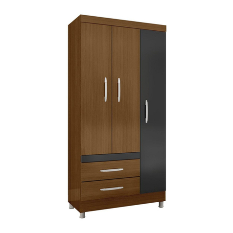
  9. Notável Móveis NT 5130 WARDROBE User manual

Notável Móveis NT 5130 WARDROBE User manual

TERMO DE GARANTIA
A presente garantia deverá ser exercida nos prazos aqui indicados,
mediante apresentação deste certificado e da nota fiscal.
Para que o produto esteja assegurado pela garantia conferida neste
documento, o cliente deverá adotar as seguintes orientações e cuidados
quanto à montagem, conservação e limpeza.
MONTAGEM
A montagem deverá ser feita obedecendo as instruções do manual
de montagem que será fornecido com o produto no momento da entrega.
Para o uso adequado e conservação do móvel deve-se evitar maus
tratos, como por exemplo: bater portas e gavetas, arrastar ou riscar o
móvel, umidade ou calor excessivos e exposição ao sol, para evitar
possível alteração na cor original dos móveis.
Não será de responsabilidade da Notável Móveis problemas que
tenham origem na utilização dos produtos de forma inadequada ou
quebra do móvel em função do excesso de peso por colocação de pedras
de granito, mármore e outros.
- O peso suportado por cada prateleira deverá obedecer os valores
indicados na ilustração.
Também não serão de responsabilidade da Notável Móveis,
problemas que tenham origem em:
- Instalações elétricas ou hidráulicas.
- Ações de cupins ou outras pragas.
- Armazenamento e deslocamento do móvel em locais impróprios e
não dedetizados periodicamente.
- Todo e qualquer recorte ou alteração nos móveis.
- Uso de produtos de limpeza ou abrasivos não recomendados.
CONSERVAÇÃO E LIMPEZA
Para maior durabilidade, recomenda-se que a limpeza dos móveis
seja feita da seguinte forma:
Nas partes externas (portas, laterais e frente de gaveta), internas,
vidros e espelhos, a limpeza deverá ser feita com pano limpo e levemente
umedecido em água e sabão neutro. Em seguida, deverá ser passado um
pano limpo e seco.
Em caso de transferência do móvel para local diverso, esta só
poderá ocorrer através de profissional especializado, sendo que para a
movimentação do móvel é necessário que o mesmo seja levantado do
chão. O produto não deve ser arrastado, pois avarias no manuseio e
transporte, não estão contempladas na garantia.
DOCUMENTO DE FIANZA
Esta garantía se ejerce dentro del
periodo en el presente documento, con
la presentación de este certificado y la
factura.
Para que el pr oducto e s t é
garantizado por la garantía dada en este
documento, el cliente debe tomar las
siguientes directrices y precauciones de
instalación, mantenimiento y limpieza.
MONTAJE
El montaje se realizará siguiendo
las instrucciones de ensamblaje que
serán proporcionadas con la entrega del
producto.
Para el uso adecuado y l a
conservación del mueble se debe evitar
los malos tratos, tales como: golpear
puertas y cajones, arrastrar o arañar los
muebles, humedad o el calor excesivos y
la exposición al sol para evitar un posible
cambio en el color original de los
muebles.
No será responsabilidad de
Notável Móveis problemas que se
originen en el uso de los productos de
forma inapropiada o ruptura del mueble
en función de exceso de peso mediante
la colocación de piedras de granito,
mármol y otros.
- El peso soportado por cada
estante debe cumplir con los valores
indicados en la ilustración.
Tampoco serán responsabilidad
de Notável Muebles los problemas que
se originan en:
- Instalaciones eléctricas o
hidráulicas.
- Acciones de termitas u otras
plagas.
- Almacenamiento y cambio del
mueble en locales inapropiados y no
fumigados periódicamente.
- Todo y cada corte o cambio en
los muebles.
- Uso de productos de limpieza o
abrasivos no recomendados.
CUIDADO Y LIMPIEZA
Para una mayor durabilidad, se
recomienda que la limpieza de los
muebles sea hecha como sigue:
En las partes externas (puertas,
laterales y frontales de cajón), internas,
vidrios y espejos, la limpieza debe ser
hecha con paño limpio y ligeramente
humedecido con agua y jabón suave. A
continuación, se debe pasar un paño
limpio y seco.
En el caso del traslado del mueble
a otro sitio, esto sólo puede ocurrir a
través de profesionales especializados,
y para el manejo del mueble se requiere
que el mismo sea levantado del piso. El
producto no debe ser arrastrado pues
daños en la manipulación y el transporte
no están cubiertos por la garantía.
WARRANTY TERM
This warranty shall be applied
within the time limits specified herein, by
presentation of this certificate and
invoice.
In order for the product to be
covered by the warranty provided in this
document, the client should follow the
following guidelines and precautions for
assembly, maintenance and cleaning.
ASSEMBLY
Assembly must be carried out
according to the instructions in the
assembly manual which is supplied with
the product at the time of delivery.
For proper use and conservation
of this furniture, mistreatment should be
avoided, such as hitting doors and
drawers, dragging or scratching the
furniture, excessive moisture or heat to
avoid possible changes in its original
color.
Problems from improper use of
the products as breaking of the furniture
due to the excess weight by installation
of granite, marble, and others will not be
the responsibility of Notável Móveis
- The weight withstood by each
shelf/drawer must comply with the
values indicated in illustration.
It will not be responsibility of the
Notável Móveis either problem from:
- E le c t r i c a l o r h y d r a u l i c
installations.
- Actions of termites or other pests.
- Storage and moving of the
furniture in inappropriate places and not
fumigated periodically.
- Any trimming or alteration in the
furniture.
- Use of cleaning agents or
abrasives not recommended.
UPKEEP AND CLEANING
For durability, it is recommended
that the furniture be cleaned this way:
In the outer parts (doors, sides
and drawer front), inside, glass and
mirrors, the cleaning should be done with
a cloth clean and lightly moistened with
mild soap and water. Then a clean, dry
cloth should be used.
In case of transfer of the furniture
to a different place, this can only be done
by specialized professionals, and for the
moving of the furniture it is necessary
that it is lifted off the ground. It should not
be dragged because malfunctions due to
handle and moving are not covered by
the warranty.
PRAZO DE GARANTIA
O prazo de garantia será de noventa (90) dias, conforme prevista no artigo 26 do Código
do Consumidor, a contar da efetiva entrega do produto, desde que observadas as condições
normais de uso e conservação. Essa garantia cobre defeitos de fabricação. A Indústria de
Móveis Notável não se responsabiliza pela garantia estendida adquirida pelos consumidores
junto aos lojistas e seguradoras, a garantia legal da fabricante é de 90 dias. Art. 26, II, CDC.”
PÁGINA | PAGINA | PAGE: 01
889988
18
18
18
1
2
2
4
3
67
10
11
15
14
16
5
17
11
12
22
22
20
13 21 21
13
21
20
21
3kg
8kg
8kg
3kg
A MARCAÇÃO DO NÚMERO DE LOTE E CÓDIGO DA PEÇA QUE APARECE NAS FITAS DE
BORDA É FACILMENTE REMOVIDA COM BORRACHA ESCOLAR OU COM PANO E ÁLCOOL
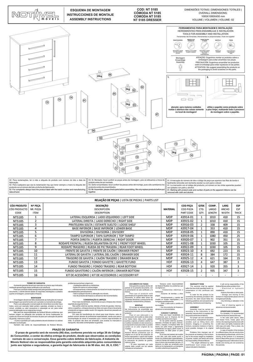
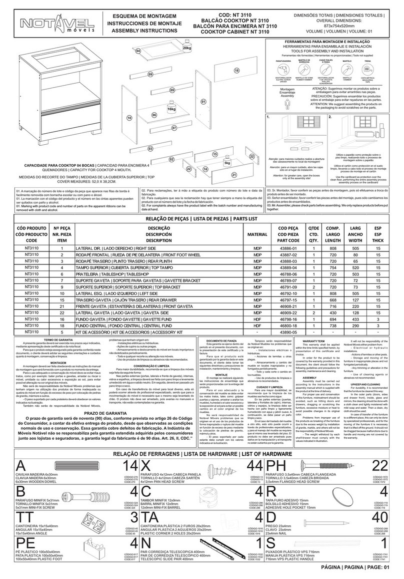
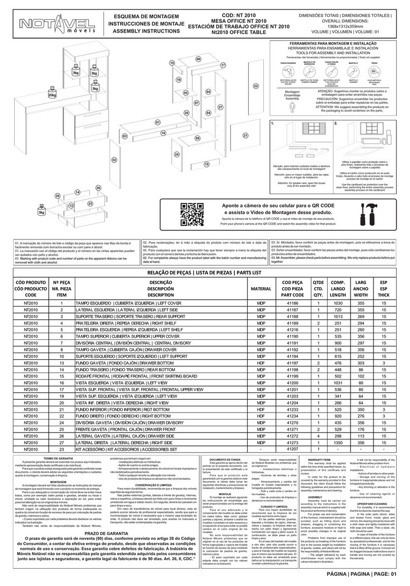
ESQUEMA DE MONTAGEM
INSTRUCCIONES DE MONTAJE
ASSEMBLY INSTRUCTIONS
COD: NT5130
GUARDA-ROUPA NT 5130
CLOSET NT 5130
NT 5130 WARDROBE
DIMENSÕES TOTAIS | DIMENSIONES TOTALES |
: 1870x1610x437mm OVERALL DIMENSIONS
VOLUME | VOLUMEN | VOLUME: 02
NT5130 1LATERAL ESQUERDA | LATERAL IZQUIERDA | LEFT SIDE MDP 49197-01 1 1820 422 12
NT5130 2 BASE DIR/ESQ | BASE DERECHA/IZQUIERDA | RIGHT/LEFT BASE MDP 49198-02 2 533 422 12
NT5130 3 DIVISORIA INF ESQ | DIV. INFERIOR IZQ | LEFT LOWER DIVISION MDP 49199-03 1 350 422 12
NT5130 4 TAMPO INF/ESQ | CUBIERTA INF/IZQ | LEFT LOWER TOP MDP 49263-04 1 1052 422 12
NT5130 5 TAMPO SUPERIOR | CUBIERTA SUPERIOR | UPPER TOP MDP 49200-05 1 1584 422 12
NT5130 6 DIVISORIA SUPERIOR | DIVISION SUPERIOR | UPPER DIVISION MDP 49264-06 1 1266 113 12
NT5130 7 DIVISORIA DIREITA | DIVISIÓN DERECHA | RIGHT DIVISORY MDP 49201-07 1 1628 422 12
NT5130 8 PORTA MAIOR | PUERTA MAYOR | GREATER DOOR MDP 47909-08 4 1636 263 15
NT5130 9 PORTA MENOR | PUERTA MENOR | MINOR DOOR MDP 47910-09 2 1274 263 15
NT5130 10 PRATELEIRA FIXA | REPISA FIJO | FIXED SHELF MDP 49265-10 1 520 420 12
NT5130 11 PRATELEIRA MÓVEL | ESTANTE SUELTO | MOBILE SHELF MDP 49266-11 2 520 420 12
NT5130 12 LATERAL DIREITA | LATERAL DERECHA | RIGHT SIDE MDP 49202-12 1 1820 422 12
NT5130 13 TRASEIRO GAVETA | TRASERO CAJÓN | REAR DRAWER MDP 47793-13 2 472 77 12
NT5130 14 RODAPÉ FRONTAL | RODAPIÉ FRONTAL | FRONT SKIRTING BOARD MDP 47794-14 1 1584 92 15
NT5130 15 RODAPÉ TRASEIRO | RODAPIÉ TRASERO | REAR SKIRTING BOARD MDP 47912-15 1 1584 92 15
NT5130 16 RODAPÉ CENTRAL | RODAPIÉ CENTRAL | CENTRAL SKIRTING BOARD MDP 47887-16 1 381 91 15
NT5130 17 RODA FORRO | RUEDO DEL FORRO | CEILING BOARD MDP 47888-17 1 1609 80 15
NT5130 18 FUNDO TRASEIRO | FONDO TRASERO | REAR BOTTOM HDF 47798-18 3 1660 533 3
NT5130 20 FRENTE GAVETA | FRONTAL CAJÓN | DRAWER FRONT MDP 49187-20 2 528 177 15
NT5130 21 LATERAL GAVETA | LATERAL CAJÓN | DRAWER SIDE MDP 49267-21 4 359 113 12
NT5130 22 FUNDO GAVETA | FONDO CAJÓN | DRAWER BOTTOM HDF 49268-22 2 495 362 3
NT5130 23 KIT ACESSÓRIOS | KIT ACCESORIOS | ACCESSORIES SET . 49203-23 1 . . .
RELAÇÃO DE PEÇAS
CÓD
PRODUTO
Nº
PEÇA DESCRIÇÃO MATERIAL QTDE COMP LARG ESPCOD PEÇA
Instalação
Instalación
Installation
01. A marcação do código da peça e do número de lote que aparece nas fitas de borda é facilmente
removida com borracha escolar ou com pano e álcool.
01. La marcación con el código del producto y el número en las cintas aparentes pueden ser quitados con
paño y alcohol.
01. Marking with product code and number of parts on the apparent ribbons can be removed with cloth and
alcohol.
02. Para reclamações, ter à mão a etiqueta do produto com número do lote e data da fabricação.
02. Para cualquiera que sea la reclamación hay que tener siempre a mano la etiqueta del producto con el
número del lote y la fecha de fabricación.
02. For complaints always have the product label with the batch number and manufacturing date at hand.
03. Sr. Montador, favor conferir as peças antes da montagem, pois só efetuamos a troca do produto antes de
ser montado.
03. Señor ensamblador, favor conferir las piezas antes del montaje, pues sólo cambiamos los productos antes
de ensamblados.
03. Mr. Assembler, please check parts before assembling. We only replace products before put together.
FERRAMENTAS PARA MONTAGEM E INSTALAÇÃO
HERRAMIENTAS PARA ENSAMBLAJE E INSTALACIÓN
TOOLS FOR ASSEMBLY AND INSTALLATION
Ferramentas não fornecidas | Herramientas no proporcionadas | Tools not supplied
Montagem
Ensamblaje
Assembly
ATENÇÃO: Sugerimos montar os produtos sobre
a embalagem para evitar arranhões nas peças.
PRECAUCIÓN: Sugerimos ensamblar los
productos sobre el embalaje para evitar
rayaduras en las partes.
ATTENTION: We suggest assembling the
products on the packaging to avoid scratches on
the parts.
DESTORNILLADOR
ELETRIC SCREW
DRIVER
MARTILLO
HAMMER
DESTORNILLADOR
Y DE CRUCETA
PHILLIPS
SCREWDRIVER
CINTA MÉTRICA
MEASURING
TAPE
5M
PARAFUSADEIRA CHAVE PHILIPS
E FENDA MARTELO TRENA
3
7
3
PASSO 1
PASO 1
STEP 1
PÁGINA | PAGINA | PAGE: 02
Faça a preparação de todas as peças, com os
acessórios e as quantidades dos mesmos.
1 - Posicione os calços de dobradiças M nas marcações
das peças 1 e 7 e fixe-os com os parafusos X (4x12mm);
2 - Para fixar o calço central na peça 7, encaixe a
dobradiça para então alinhar o calço na posição correta,
e fixe-os com os parafusos X (4x12mm), faça o mesmo
procedimento para fixar o calço superior na peça 1;
3 - Posicione 2 calços de dobradiças M alinhados aos
furos superiores da peça 7. Utilize os parafusos PC
(5X32mm) para fixar o conjunto com 2 calços, sendo um
de cada lado das peças;
4 - Encaixe os suportes calceiro LL nas peças 1 e 7.
Prepare todas las piezas, con accesorios y cantidades.
1 - Coloque los calzos de bisagra M en las marcas de
las partes 1 y 7 y fíjelos con los tornillos X (4x12 mm);
2 - Para fijar el calzo central en la parte 7, encajar la
bisagra para luego alinear el calzo en la posición
correcta, y fijarlos con los tornillos X (4x12mm), hacer el
mismo procedimiento para fijar el calzo superior en la
parte 1;
3 - Coloque 2 calzos de bisagra M alineados con los
agujeros superiores de la pieza 7. Utilice los tornillos PC
(5X32mm) para fijar el conjunto con 2 bloques, uno a
cada lado de las piezas;
4 - Montar los soportes LL en las piezas 1 y 7.
Prepare all parts, with accessories and quantities.
1 - Position the M hinge wedges at the markings on parts
1 and 7 and fix them with the X screws (4x12mm);
2 - To fix the central wedge on part 7, fit the hinge to then
align the wedge in the correct position, and fix them with
the X screws (4x12mm), do the same procedure to fix
the upper wedge on part 1;
3 - Position 2 M hinge wedges aligned with the top holes
of the piece 7. Use the PC screws (5X32mm) to fix the
set with 2 wedges, one on each side of the pieces;
4 - Fit the LL angle support to parts 1 and 7.
M9
X14
LL 2
1 7
PC 2
1 - Posicione o calço de dobradiça M na marcação da
peças 3 e fixe-os com os parafusos X (4x12mm)
2 - Posicione as corrediças N nas marcações das peças 3
e 7, fixe-as com os parafusos PP (3x12mm);
3 - Insira as cavilhas A (6x30mm) no topo e na base das
peças 3 e 7.
1 - Posicionar el calzo de bisagras M en la marca de las
piezas 3 y fijarlas con los tornillos X (4x12mm)
2 - Colocar las correderas N en las marcas de las piezas
3 y 7, fijarlas con tornillos PP (3x12mm);
3 - Inserte los pasadores A (6x30 mm) en la parte superior
e inferior de las partes 3 y 7.
1 - Position the hinge wedge M in the marking of the parts
3 and fix them with the screws X (4x12mm)
2 - Position slides N in the markings of parts 3 and 7, fix
them with PP screws (3x12mm);
3 - Insert pins A (6x30mm) on the top and bottom of parts
3 and 7.
N4
PP 8
A8
M1
X2
PASSO 2
PASO 2
STEP 2
CA 1
RELAÇÃO DE FERRAGENS
34
D
S
100
8
W16
N2
M18
R10
T8
X122
L9
4
PH 27
Y9
14
PE 6
PP 16
LL 2
PG 2
TA 4
KL 1
SUPORTE CABIDEIRO U CENTRAL
SOPORTE DE COLGADOR CENTRAL EN U
CENTRAL U HANGER SUPPORT
8
J
BATENTE - SUP. PARA PRATELEIRA PLÁSTICO 16x8x8mm
BATIENTE - SOP. ESTANTE PLASTICO 16X8X8MM
16X8X8MM STOPPER – PLASTIC SHELF SUPPORT
A
CAVILHA MADEIRA 6x30mm
CLAVIJA MADERA 6x30mm
6X30MM WOODEN DOWEL
FUNDO JUNÇÃO METÁLICO 13X13mm
FONDO JUNCIÓN METÁLICO 13x13mm
METALIC BOTTOM JUNCTION 13X13mm
EEE
PREGO 23x4mm
CLAVO 23x4mm
23X4MM NAIL
PARAFUSO 3,5X25MM CABEÇA CHATA
TORNILLO 3,5X25MM CABEZA PLANA
3.5X25MM FLAT HEAD SCREW
PARAFUSO 3,5x40mm CABEÇA CHATA
TORNILLO 3,5x40mm CABEZA PLANA
3.5X40MM FLAT HEAD SCREW
PARAFUSO 5x32mm CABEÇA CHATA COM PORCA
TORNILLO 5x32mm CABEZA PLANA CON TUERCA
SCREW CHATA HEAD WITH NUT 5x32mm
PC
DOBRADIÇA CURVA 26mm COM CALÇO 5mm - METÁLICA
BISAGRA CURVA 26mm CON CALZO 5mm - METÁLICA 26mm
METAL CURVE HINGE WITH 5mm PAG
PAR CORREDIÇA METÁLICA 350mm
PAR CORREDIZA METÁLICA 350mm
350MM PAIR OF SLIDES
PUXADOR PLÁSTICO 128mm
MANIJA PLÁSTICA 128mm
128MM PLASTIC HANDLE
CANTONEIRA PLÁSTICA 2 FUROS 18X18 mm
ANGULAR PLÁSTICA 2 AGUJEROS 18X18 mm
PLASTIC CORNER 2 HOLES 18X18 mm
CABIDEIRO
PERCHERO
HANGER
PARAFUSO 3X12mm CABEÇA CHATA
3X12mm CABEZA PLANA
3X12mm FLAT HEAD SCREW
SUPORTE PLASTICO CALCEIRO/CABIDEIRO
SOPORTO PANTALONERA/COLGADOR
12X12X6MM PLASTIC SLIDING SHOE
PÉ PLÁSTICO QUADRADO 40x98mm
PATA PLÁSTICA 40x98MM
PLASTIC LEG
PARAFUSO 3,5x40mm CABEÇA FLANGEADA
TORNILLO 3,5x40mm CABEZA BRIDADA
3.5X40MM FLANGED HEAD SCREW
SAPATA DESLIZADORA PLÁSTICA 12x12x6mm
ZAPATA DESLIZADORA PLÁSTICA 12x12x6mm
12x12x6mm PLASTIC SLIP SHOE
PARAFUSO 4X12mm CABEÇA PANELA
4X12mm CABEZA CUCHARA
4X12mm PAN HEAD SCREW
CANTONEIRA 15x15x40mm
ANGULAR 15x15x40mm
15X15X40MM ANGLE
TAPA FURO ADESIVO PLÁSTICO 15mm
TAPA-AGUJERO ADHESIVO PLÁSTICO 15mm
15MM PLASTIC ADHESIVE HOLE COVER
PARAFUSO 3,5X20mm CABEÇA CHATA
TORNILLO 3,5X20mm CABEZA PLANA
3,5X20MM FLAT HEAD SCREW
PASSO 3
PASO 3
STEP 3
1 - Posicione os calços de dobradiças M nas marcações
da peça 12 e fixe-os com os parafusos X (4x12mm);
2 - Para fixar o calço central na peça 12, encaixe a
dobradiça para então alinhar o calço na posição correta,
e fixe-os com os parafusos X (4x12mm);
3 - Encaixe os batentes J nas peças 7 e 12
1 - Coloque los calzos de bisagra M en las marcas de la
pieza 12 y fíjelos con los tornillos X (4x12mm);
2 - Para fijar la cuña central en la pieza 12, colocar la
bisagra para luego alinear la cuña en la posición
correcta, y fijarlas con los tornillos X (4x12mm);
3 - Montar los batientes en J en las piezas 7 y 12.
1 - Position the M hinge wedge at the markings on part
12 and fix them with the X screws (4x12mm);
2 - To fix the central shim on part 12, fit the hinge to then
align the shim in the correct position, and fix them with
the X screws (4x12mm);
3 - Fit the J stops on parts 7 and 12.
M3
X6
12
7
J8
6
.1 - Posicione os calços de dobradiças M nas marcações da
peça 6 e fixe-os com os parafusos X (4x12mm);
2 - Para fixar o calço central na peça 6, encaixe a dobradiça
para então alinhar o calço na posição correta, e fixe-os com
os parafusos X (4x12mm);
3 - Posicione 2 calços de dobradiças M alinhados aos furos
superiores da peça 6. Utilize os parafusos PC (5X32mm)
para fixar o conjunto com 2 calços, sendo um de cada lado
das peças;
4 - Insira as cavilhas A (6x30mm) no topo e base da peça 6.
1 - Coloque los calzos de bisagra M en las marcas de la
parte 6 y fíjelos con los tornillos X (4x12 mm);
2 - Para fijar el calzo central en la pieza 6, colocar la bisagra
para luego alinear el calzo en la posición correcta, y fijarlos
con los tornillos X (4x12mm);
3 - Colocar 2 calzos de bisagra M alineados con los orificios
superiores de la pieza 6. Utilizar los tornillos PC (5X32mm)
para fijar el conjunto con 2 calzos, uno a cada lado de las
piezas;
4 - Inserte los pines A (6x30mm) en la parte superior e
inferior de la parte 6.
.1 - Position the M hinge wedge at the markings on part 6
and secure them with the X screws (4x12mm);
2 - To fix the central wedge on part 6, fit the hinge to then
align the wedge in the correct position, and fix them with the
X screws (4x12mm);
3 - Position 2 M hinge wedge aligned with the upper holes of
the piece 6. Use the PC screws (5X32mm) to fix the set with
2 wedges, one on each side of the pieces;
4 - Insert A dowels (6x30mm) in the top and bottom of part 6.
M5
X6
PC 2
PASSO 4
PASO 4
STEP 4
A2
PASSO 5
PASO 5
STEP 5
1- Insira as cavilhas A (6x30mm) nas peças 2 e 10.
1 - Insertar las clavijas A (6x30mm) en las piezas 2 y 10.
1 - Insert A dowels (6x30mm) to parts 2 and 10.
A8
2
2
10
PASSO 6
PASO 6
STEP 6
5
4
1- Insira as cavilhas A (6x30mm) nas peças 4 e 5.
1 - Insertar las clavijas A (6x30mm) en las piezas 4 y 5.
1 - Insert the A dowels (6x30mm) to parts 4 and 5.
A8
PASSO 7
PASO 7
STEP 7
Y3
4
5
6
7
1 - Encaixe a peça 4 na 7 e a 6 na 4 e fixe-as com os
parafusos Y (3,5x40mm);
2 - Encaixe a peça 6 e 7 na 5 e fixe-as com o parafuso
PH (3,5X40mm)
1 - Montar las piezas 4 a 7 y 6 a 4 y fijarlas con tornillos
Y (3,5x40mm);
2 - Colocar la pieza 6 y 7 en la pieza 5 y fijarlas con el
tornillo PH (3,5X40mm)
1 - Fit part 4 to 7 and 6 to 4 and fix them with Y screws
(3.5x40mm);
2 - Fit part 6 and 7 to part 5 and fix them with the PH
screw (3.5X40mm)
YY
PH
PH 3
43
Y2
PASSO 8
PASO 8
STEP 8
1 - Encaixe a peça 3 na 4 e fixe-a com os parafusos Y
(3,5x40mm).
1 - Encaje la pieza 3 en la 4 y fijela con los tornillos Y
(3,5x40mm)
1 - Fix the piece 3 at 4 and fix them with Y screws
(3,5x40mm)
PH 4
PASSO 9
PASO 9
STEP 9
2
2
37
1 - Encaixe as peças 2 na 3 e 7 e fixe-as com os
parafusos PH (3,5x40mm).
1- Encaje las piezas 2 en la 3 y 7 y fijelas con los
tornillos PH (3,5x40mm)
1 - Fit the parts 2 at 3 and 7 and fix them with PH
screws (3,5x40mm)
PASSO 10
PASO 10
STEP 10
12
10
2
5
1 - Encaixe a peça 12 na 2, 5 e 10 e fixe-as com os
parafusos PH (3,5x40mm).
1 - Encaje la pieza 12 en la 2, 5 y 10 y fijelas con los
tornillos PH (3,5x40mm).
1 - Fit the piece 12 at 2, 5 and 10 and fix them with PH
(3,5x40mm)
PH 5
PASSO 11
PASO 11
STEP 11
1 - Fixe o cabideiro KL na marcação da peça 5 com os
parafusos PG (3,5x20mm);
2 - Antes de fixar a peça 1, encaixe o cabideiro CA no
suporte cabideiro KL;
3 - Em seguida, encaixe a peça 1 na 2,4 e 5 e fixe-as
com os parafusos PH (3,5x40mm).
1 - Fije el perchero KL a la marca de la pieza 5 con los
tornillos PG (3,5x20 mm);
2 - Antes de fijar la pieza 1, coloque el rack AC en el
soporte del rack KL;
3 - A continuación, coloque la pieza 1 en 2.4 y 5 y fíjelas
con tornillos PH (3.5x40mm).
1 - Secure the KL clothes rack to the marking of part 5
with the PG screws (3.5x20mm);
2 - Before fixing part 1, fit the AC rack to the KL rack
holder;
3 - Then, fit part 1 to 2.4 and 5 and fix them with PH
screws (3.5x40mm).
PH 6
KL 1
1
57
4
2
5
PG 2
CA 1
X8
T2
PASSO 12
PASO 12
STEP 12
14
15
16
12
1
1 - Encaixe a peça 14 e 15 entre as peças 1 e 12 e fixe-
as com os parafusos PH (3,5x40mm);
2 - Fixe a peça 16 centralizada entre as peças 14 e 15,
utilizado as cantoneiras T e os parafusos X (4x12mm);
1 - Montar las piezas 14 y 15 entre las piezas 1 y 12 y
fijarlas con tornillos PH (3,5x40mm);
2 - Fijar la pieza 16 centrada entre las piezas 14 y 15,
utilizando las escuadras T y los tornillos X (4x12mm);
1 - Fit part 14 and 15 between parts 1 and 12 and fix
them with PH screws (3.5x40mm);
2 - Fix part 16 centered between parts 14 and 15, using
the angle brackets T and the screws X (4x12mm);
PH 8
1 - Se optar por usar pés PE: fixe 4 pés entre as laterais e os
rodapés com os parafusos X (4x12mm);
2 - Fixe 2 pés entre o rodapé central e os rodapés frontal e
traseiro com os parafusos X (4x12mm);
3 - Se optar por usar sapatas L: fixe 2 sapatas em cada
lateral; 2 sapatas no rodapé frontal e 2 no rodapé traseiro; 1
sapata no rodapé central.
1 - Si opta por utilizar pies de PE: fije 4 pies entre los lados y
los zócalos con los tornillos X (4x12 mm);
2 - Fije 2 pies entre el rodapié central y los rodapiés
delantero y trasero con los tornillos X (4x12 mm);
3 - Si elige usar zapatos L: coloque 2 zapatos en cada lado;
2 zapatos en el pie de página delantero y 2 e
n el pie de página trasero; 1 zapato en el pie central.
1 - If you choose to use PE feet: fix 4 feet between the sides
and baseboards with the X screws (4x12mm);
2 - Secure 2 feet between the central baseboard and the
front and rear baseboards with the X screws (4x12mm);
3 - If you choose to use L shoes: attach 2 shoes on each
side; 2 shoes on the front footer and 2 on the rear footer; 1
shoe in the central footer.
PE 6
X18
PASSO 13
PASO 13
STEP 13
L9
PASSO 14
PASO 14
STEP 14
1 - Fixe a peça 17 alinhada nas laterais 1 e 12 e no
tampo 5 com as cantoneiras T e os parafusos X
(4x12mm).
1 - Fijar la pieza 17 alineada en los lados 1 y 12 y en la
parte superior 5 con los ángulos T y los tornillos X
(4x12mm).
1 - Fix the part 17 aligned on the sides 1 and 12 and on
the top 5 with the angles T and the screws X (4x12mm).
X24
6
T
17 5
1 - ATENÇÃO: Antes de fixar os fundos verifique o esquadro
do armário
2 - Alinhe uma peça 18 a lateral, ao tampo e a base do
armário e fixe-a com os pregos D
3 - Em se
guida, alinhe as demais peças 18 e fixe-as com os pregos D
4 - Na junção entre as peças 18 utilize os fixadores E em
conjunto com os pregos D
1 - ATENCIÓN: Antes de arreglar los fondos, verifique el
cuadrado del gabinete
2 - Alinear una pieza 18 con el lateral, la parte superior y la
base del mueble y fijarlo con clavos D
3 - En si
guiado, alinear las otras piezas 18 y fijarlas con clavos D
4 - Al unir las piezas 18, utilice los sujetadores E junto con los
clavos D
1 - ATTENTION: Before fixing the funds, check the square of
the cabinet
2 - Align a piece 18 with the side, the top and the base of the
cabinet and fix it with nails D
3 - In if guided, align the other pieces 18 and fix them with
nails D
4 - When joining pieces 18, use fasteners E together with
nails D
D80
E14
18
18
18
PASSO 15
PASO 15
STEP 15
PÁGINA | PAGINA | PAGE: 03
PASSO 16
PASO 16
STEP 16
1 - Insira as cavilhas A (6x30mm) nas peças 21
2 - Em seguida fixe as peças 21 na peça 13 com os
parafusos Y (3,5x40mm)
1- Introduzca las clavijas A (6x30mm) en las piezas 21.
2 - Luego, fije las piezas 21 en la pieza 13 con los
tornillos Y
(3,5x40mm).
1 - Insert pins A (6x30mm) into parts 21
2 - Then fix parts 21 to part 13 with the screw Y
(3.5x40mm)
Y4
A8
21
21 13
X8
TA 4
20
20
21 21
PASSO 17
PASO 17
STEP 17
1 - Encaixe a peça 20 no conjunto montado no passo
anterior
2 - Fixe as peças 21 na peça 20 utilizando as cantoneiras
TA e os parafusos X (4x12mm)
1 - Encaje la pieza 20 en el conjunto ensamblado en el
paso anterior.
2 - Fije las piezas 21 en la pieza 20 con las angulares TA
y los tornillos X (4x12mm)
1 - Fit the set assembled on the previous step to part 20
2 - Fit partes 21 into part 20 using TA angles and the X
screws (4x12mm)
PP 8
N2
D20
1 - Encaixe o fundo 22 na frente de gaveta e alinhe-o
as laterais e ao traseiro da gaveta. Fixe com os pregos
D.
2 - Encoste a corrediça N na frente de gaveta e no
fundo 22 e fixe-a com os parafusos PP (3x12mm)
1 - Encaje el fondo 22 en el frontal de cajón y alinéelo a
las laterales y al trasero del cajón. Fíjela con los clavos
D.
2 - Apoye la corrediza N en el frontal de cajón y en el
fondo 22 y fíjela con los tornillos PP (3x12mm).
1 - Fit the bottom 22 in front of drawer and align on
sides and rear of the drawer. Fix with D nails.
2 - Fit the N slides in front of drawer and on the bottom
22 and fix with (3x12mm) PP screws.
22
PASSO 18
PASO 18
STEP 18
PASSO 19
PASO 19
STEP 19
1 - Alinhe os puxadores S nos furos das frentes de
gaveta e fixe-os com os parafusos W (3,5x25mm)
1 - Alinee las manijas S en los agujeros de los frontales
de cajón y fíjelas con los tornillos W (3,5x25mm).
1 – Align the S Handles on the doors front holes, than
fasten them with (3,5x25mm) W screws.
W
S
4
2
1 - Insira as peças 11 sobre os batentes J já fixados na
peça 7 e 12.
1 - Insertar las piezas 11 sobre los batientes J fijados en
las piezas 7 y 12
1 - Insert parts 11 on the J stops already fixed on parts 7
and 12.
PASSO 20
PASO 20
STEP 20
11
11
712
PASSO 21
PASO 21
STEP 21
88
9
9
1 - Encaixe as dobradiças M nas portas 8 e 9 e fixe-as
com os parafusos X (4x12mm)
1 - Encaje las bisagras M en las puertas 8 y 9 y fíjelas
con los tornillos X (4x12mm).
1 – Fit the M Hinges to the doors 8 & 9, then fasten them
with 4x12mm X screws.
X
M
36
18
PASSO 22
PASO 22
STEP 22
W
S
12
6
1 - Alinhe os puxadores S nos furos das portas e fixe-os
com os parafusos W(3,5x25mm).
1 - Alinee las manijas S en los agujeros de las puertas y
fíjelas con los tornillos W (3,5x25mm).
1 – Align the S Handles on the doors holes and fasten
them with (3,5x25mm) W screws.
1 - Para montar a porta, encaixe as dobradiças M nos calços
M travando-a no parafuso indicado com o número 1 abaixo:
1 - Para ensamblar la puerta, encaje las bisagras M en los
calzos M trabándola al tornillo indicado con el nro. 1 abajo.
1 - To mount the door, fit the M hinges on the M hinge pads
by locking it to the screw indicated with # 1 below.
M
18
18
M
1
PASSO 23
PASO 23
STEP 23
PASSO 24
PASO 24
STEP 24
R10
1 - Encaixe as gavetas no armário
2 - Cole os tapa-furos adesivo R sobre os furos restantes
do produto.
1. Encaje los cajones el armario.
2. Coloque el tapa-agujero adhesivo R sobre los agujeros
restantes del producto.
1 – Fit the drawers into the cabinet.
2 – Place the R Hole cover on the other holes.
1
2
3
Para regulagem das portas siga as instruções conforme número abaixo:
1 - Se precisar subir ou abaixar um pouco a porta desaperte um pouco
os parafusos indicados com o número 1, reposicione e aperte
novamente.
2 - Se precisar empurrar a porta um pouco mais para dentro ou puxá-la
para fora, desaperte um pouco o parafuso indicado com o nº 2,
reposicione e aperte novamente.
3 - Se precisar alinhar as portas um pouco mais para o centro ou em
direção as laterais, utilize uma chave philips para girar o parafuso
indicado com o nº 3 até posicionar a porta da forma desejada.
Para ajustar las puertas, siga las instrucciones conforme a
continuación:
1 - Si tiene que subir o bajar un poco la puerta, afloje un poco los
tornillos que se indican con el número 1, reposicione y vuelva a apretar.
2 - Si tiene que empujar la puerta un poco más para el interior o hallarla
afuera, afloje un poco el tornillo que se indica con el número 2,
reposicione y vuelva a apretar.
3 - Si tiene que alinear las puertas un poco más hacia el centro o hacia
los lados, use un destornillador de cruceta para girar el tornillo indicado
con el número 3 hasta posicionar la puerta de forma deseada.
To adjust the doors, follow the instructions below:
1. If you need to raise or lower the door a little, loosen the screws
indicated with # 1, reposition and tighten again.
2. If you need to push the door a little further in or pull it out, loosen the
screw indicated with # 2, reposition it and tighten again.
3. If you need to align the doors a little further towards the center or
toward the sides, use a Philips screwdriver to rotate the screw indicated
with # 3 until you position the door the way you want.
PÁGINA | PAGINA | PAGE: 04

Other Notável Móveis Indoor Furnishing manuals

Notável Móveis NT1135 User manual

Notável Móveis

Notável Móveis NT1135 User manual

Notável Móveis NT 5185 User manual

Notável Móveis

Notável Móveis NT 5185 User manual

Notável Móveis SHOE CABINET ALASKA NEW 56126 User manual

Notável Móveis

Notável Móveis SHOE CABINET ALASKA NEW 56126 User manual

Notável Móveis NT1180 User manual

Notável Móveis

Notável Móveis NT1180 User manual

Notável Móveis NT 3110 User manual

Notável Móveis

Notável Móveis NT 3110 User manual

Notável Móveis NT 4020 MULTIPURPOSE User manual

Notável Móveis

Notável Móveis NT 4020 MULTIPURPOSE User manual

Notável Móveis NT 2005 User manual

Notável Móveis

Notável Móveis NT 2005 User manual

Notável Móveis NT 1195 User manual

Notável Móveis

Notável Móveis NT 1195 User manual

Notável Móveis NT 2000 User manual

Notável Móveis

Notável Móveis NT 2000 User manual

Notável Móveis NT 2010 User manual

Notável Móveis

Notável Móveis NT 2010 User manual

Notável Móveis 55012 User manual

Notável Móveis

Notável Móveis 55012 User manual

Notável Móveis NT5000 User manual

Notável Móveis

Notável Móveis NT5000 User manual

Notável Móveis NT 5015 User manual

Notável Móveis

Notável Móveis NT 5015 User manual

Notável Móveis 55002 User manual

Notável Móveis

Notável Móveis 55002 User manual

Notável Móveis 56118 User manual

Notável Móveis

Notável Móveis 56118 User manual

Notável Móveis NT5165 User manual

Notável Móveis

Notável Móveis NT5165 User manual

Notável Móveis NT3075 User manual

Notável Móveis

Notável Móveis NT3075 User manual

Notável Móveis CHICAGO 56100 User manual

Notável Móveis

Notável Móveis CHICAGO 56100 User manual

Notável Móveis NT 1195 User manual

Notável Móveis

Notável Móveis NT 1195 User manual

Notável Móveis NT 4015 User manual

Notável Móveis

Notável Móveis NT 4015 User manual

Notável Móveis PAINEL NT 1200 User manual

Notável Móveis

Notável Móveis PAINEL NT 1200 User manual

Notável Móveis NT 1205 User manual

Notável Móveis

Notável Móveis NT 1205 User manual

Notável Móveis NT 1295 User manual

Notável Móveis

Notável Móveis NT 1295 User manual

Notável Móveis NT 1200 User manual

Notável Móveis

Notável Móveis NT 1200 User manual

Popular Indoor Furnishing manuals by other brands

velda 3L PP180215 instructions

velda

velda 3L PP180215 instructions

Next 979185 Assembly instructions

Next

Next 979185 Assembly instructions

Poliman Moveis Roupeiro Lotus 3301 Assembling instructions

Poliman Moveis

Poliman Moveis Roupeiro Lotus 3301 Assembling instructions

Sauder Office Port 408294 manual

Sauder

Sauder Office Port 408294 manual

LumiSource Folia TV-FOLIA2 Series Assembly instructions

LumiSource

LumiSource Folia TV-FOLIA2 Series Assembly instructions

Amart Furniture NIARA 75437 Assembly instruction

Amart Furniture

Amart Furniture NIARA 75437 Assembly instruction

Form LINKS 3663602991595 Assembly instruction

Form

Form LINKS 3663602991595 Assembly instruction

Bilt TRINITY TBFZ-0960 owner's manual

Bilt

Bilt TRINITY TBFZ-0960 owner's manual

Next 360116 Assembly instructions

Next

Next 360116 Assembly instructions

PHI VILLA THD-E02GS010 Use and care guide

PHI VILLA

PHI VILLA THD-E02GS010 Use and care guide

Venjakob 1590 Assembly instructions

Venjakob

Venjakob 1590 Assembly instructions

ofichairs Orlando How to Adjust

ofichairs

ofichairs Orlando How to Adjust

aspenhome IUAB-301-1 Assembly instructions

aspenhome

aspenhome IUAB-301-1 Assembly instructions

bodhi 5059413684524 Assembly

bodhi

bodhi 5059413684524 Assembly

Next CHILTERN SMALL SIDEBOARD Assembly instructions

Next

Next CHILTERN SMALL SIDEBOARD Assembly instructions

Germania Kleiderschrank 0888 Assembly instruction

Germania

Germania Kleiderschrank 0888 Assembly instruction

Ehrenkind HB01 Instructions for use

Ehrenkind

Ehrenkind HB01 Instructions for use

Global Industrial 293232 user manual

Global Industrial

Global Industrial 293232 user manual

manuals.online logo
manuals.online logoBrands
  • About & Mission
  • Contact us
  • Privacy Policy
  • Terms and Conditions

Copyright 2025 Manuals.Online. All Rights Reserved.