manuals.online logo
Brands
  1. Home
  2. •
  3. Brands
  4. •
  5. Notável Móveis
  6. •
  7. Indoor Furnishing
  8. •
  9. Notável Móveis NT 1200 User manual

Notável Móveis NT 1200 User manual

TERMO DE GARANTIA
A presente garantia deverá ser exercida nos prazos aqui indicados,
mediante apresentação deste certificado e da nota fiscal.
Para que o produto esteja assegurado pela garantia conferida neste
documento, o cliente deverá adotar as seguintes orientações e cuidados
quanto à montagem, conservação e limpeza.
MONTAGEM
A montagem deverá ser feita obedecendo as instruções do manual
de montagem que será fornecido com o produto no momento da entrega.
Para o uso adequado e conservação do móvel deve-se evitar maus
tratos, como por exemplo: bater portas e gavetas, arrastar ou riscar o
móvel, umidade ou calor excessivos e exposição ao sol, para evitar
possível alteração na cor original dos móveis.
Não será de responsabilidade da Notável Móveis problemas que
tenham origem na utilização dos produtos de forma inadequada ou
quebra do móvel em função do excesso de peso por colocação de pedras
de granito, mármore e outros.
- O peso suportado por cada prateleira deverá obedecer os valores
indicados na ilustração.
Também não serão de responsabilidade da Notável Móveis,
problemas que tenham origem em:
- Instalações elétricas ou hidráulicas.
- Ações de cupins ou outras pragas.
- Armazenamento e deslocamento do móvel em locais impróprios e
não dedetizados periodicamente.
- Todo e qualquer recorte ou alteração nos móveis.
- Uso de produtos de limpeza ou abrasivos não recomendados.
CONSERVAÇÃO E LIMPEZA
Para maior durabilidade, recomenda-se que a limpeza dos móveis
seja feita da seguinte forma:
Nas partes externas (portas, laterais e frente de gaveta), internas,
vidros e espelhos, a limpeza deverá ser feita com pano limpo e levemente
umedecido em água e sabão neutro. Em seguida, deverá ser passado um
pano limpo e seco.
Em caso de transferência do móvel para local diverso, esta só
poderá ocorrer através de profissional especializado, sendo que para a
movimentação do móvel é necessário que o mesmo seja levantado do
chão. O produto não deve ser arrastado, pois avarias no manuseio e
transporte, não estão contempladas na garantia.
DOCUMENTO DE FIANZA
Esta garantía se ejerce dentro del
periodo en el presente documento, con
la presentación de este certificado y la
factura.
Para que el pr o ducto e s t é
garantizado por la garantía dada en este
documento, el cliente debe tomar las
siguientes directrices y precauciones de
instalación, mantenimiento y limpieza.
MONTAJE
El montaje se realizará siguiendo
las instrucciones de ensamblaje que
serán proporcionadas con la entrega del
producto.
Para el uso adecuado y la
conservación del mueble se debe evitar
los malos tratos, tales como: golpear
puertas y cajones, arrastrar o arañar los
muebles, humedad o el calor excesivos y
la exposición al sol para evitar un posible
cambio en el color original de los
muebles.
No será responsabilidad de
Notável Móveis problemas que se
originen en el uso de los productos de
forma inapropiada o ruptura del mueble
en función de exceso de peso mediante
la colocación de piedras de granito,
mármol y otros.
- El peso soportado por cada
estante debe cumplir con los valores
indicados en la ilustración.
Tampoco serán responsabilidad
de Notável Muebles los problemas que
se originan en:
- Instalaciones eléctricas o
hidráulicas.
- Acciones de termitas u otras
plagas.
- Almacenamiento y cambio del
mueble en locales inapropiados y no
fumigados periódicamente.
- Todo y cada corte o cambio en
los muebles.
- Uso de productos de limpieza o
abrasivos no recomendados.
CUIDADO Y LIMPIEZA
Para una mayor durabilidad, se
recomienda que la limpieza de los
muebles sea hecha como sigue:
En las partes externas (puertas,
laterales y frontales de cajón), internas,
vidrios y espejos, la limpieza debe ser
hecha con paño limpio y ligeramente
humedecido con agua y jabón suave. A
continuación, se debe pasar un paño
limpio y seco.
En el caso del traslado del mueble
a otro sitio, esto sólo puede ocurrir a
través de profesionales especializados,
y para el manejo del mueble se requiere
que el mismo sea levantado del piso. El
producto no debe ser arrastrado pues
daños en la manipulación y el transporte
no están cubiertos por la garantía.
WARRANTY TERM
This warranty shall be applied
within the time limits specified herein, by
presentation of this certificate and
invoice.
In order for the product to be
covered by the warranty provided in this
document, the client should follow the
following guidelines and precautions for
assembly, maintenance and cleaning.
ASSEMBLY
Assembly must be carried out
according to the instructions in the
assembly manual which is supplied with
the product at the time of delivery.
For proper use and conservation
of this furniture, mistreatment should be
avoided, such as hitting doors and
drawers, dragging or scratching the
furniture, excessive moisture or heat to
avoid possible changes in its original
color.
Problems from improper use of
the products as breaking of the furniture
due to the excess weight by installation
of granite, marble, and others will not be
the responsibility of Notável Móveis
- The weight withstood by each
shelf/drawer must comply with the
values indicated in illustration.
It will not be responsibility of the
Notável Móveis either problem from:
- E le c t r i c a l o r h y d r a u l i c
installations.
- Actions of termites or other pests.
- Storage and moving of the
furniture in inappropriate places and not
fumigated periodically.
- Any trimming or alteration in the
furniture.
- Use of cleaning agents or
abrasives not recommended.
UPKEEP AND CLEANING
For durability, it is recommended
that the furniture be cleaned this way:
In the outer parts (doors, sides
and drawer front), inside, glass and
mirrors, the cleaning should be done with
a cloth clean and lightly moistened with
mild soap and water. Then a clean, dry
cloth should be used.
In case of transfer of the furniture
to a different place, this can only be done
by specialized professionals, and for the
moving of the furniture it is necessary
that it is lifted off the ground. It should not
be dragged because malfunctions due to
handle and moving are not covered by
the warranty.
PRAZO DE GARANTIA
O prazo de garantia será de noventa (90) dias, conforme prevista no artigo 26 do Código
do Consumidor, a contar da efetiva entrega do produto, desde que observadas as condições
normais de uso e conservação. Essa garantia cobre defeitos de fabricação. A Indústria de
Móveis Notável não se responsabiliza pela garantia estendida adquirida pelos consumidores
junto aos lojistas e seguradoras, a garantia legal da fabricante é de 90 dias. Art. 26, II, CDC.”
01. A marcação do número de lote e código da peça que aparece nas fitas de borda é
facilmente removida com borracha escolar ou com pano e álcool.
01. La marcación con el código del producto y el número en las cintas aparentes pueden
ser quitados con paño y alcohol.
01. Marking with product code and number of parts on the apparent ribbons can be
removed with cloth and alcohol.
02. Para reclamações, ter à mão a etiqueta do produto com número do lote e data da
fabricação.
02. Para cualquiera que sea la reclamación hay que tener siempre a mano la etiqueta del
producto con el número del lote y la fecha de fabricación.
02. For complaints always have the product label with the batch number and manufacturing
date at hand.
03. Sr. Montador, favor conferir as peças antes da montagem, pois só efetuamos a troca do
produto antes de ser montado.
03. Señor ensamblador, favor conferir las piezas antes del montaje, pues sólo cambiamos los
productos antes de ensamblados.
03. Mr. Assembler, please check parts before assembling. We only replace products before put
together.
FERRAMENTAS PARA MONTAGEM E INSTALAÇÃO
HERRAMIENTAS PARA ENSAMBLAJE E INSTALACIÓN
TOOLS FOR ASSEMBLY AND INSTALLATION
Ferramentas não fornecidas | Herramientas no proporcionadas | Tools not supplied
Montagem
Ensamblaje
Assembly
ATENÇÃO: Sugerimos montar os produtos sobre a
embalagem para evitar arranhões nas peças.
PRECAUCIÓN: Sugerimos ensamblar los productos
sobre el embalaje para evitar rayaduras en las partes.
ATTENTION: We suggest assembling the products on
the packaging to avoid scratches on the parts.
DESTORNILLADOR
ELETRIC SCREW
DRIVER
MARTILLO
HAMMER
DESTORNILLADOR
Y DE CRUCETA
PHILLIPS
SCREWDRIVER
CINTA MÉTRICA
MEASURING
TAPE
5M
PARAFUSADEIRA CHAVE PHILIPS
E FENDA MARTELO TRENA
MARTILLO DE GOMA
RUBBER HAMMER
MARTELO DE
BORRACHA
1. 2.
atenção: para maiores cuidados
realize a abertura das caixas somente
no local de montagem!
utilize o papelão como proteção sobre
o piso limpo, realizando todo o processo
de montagem sobre o papelão.
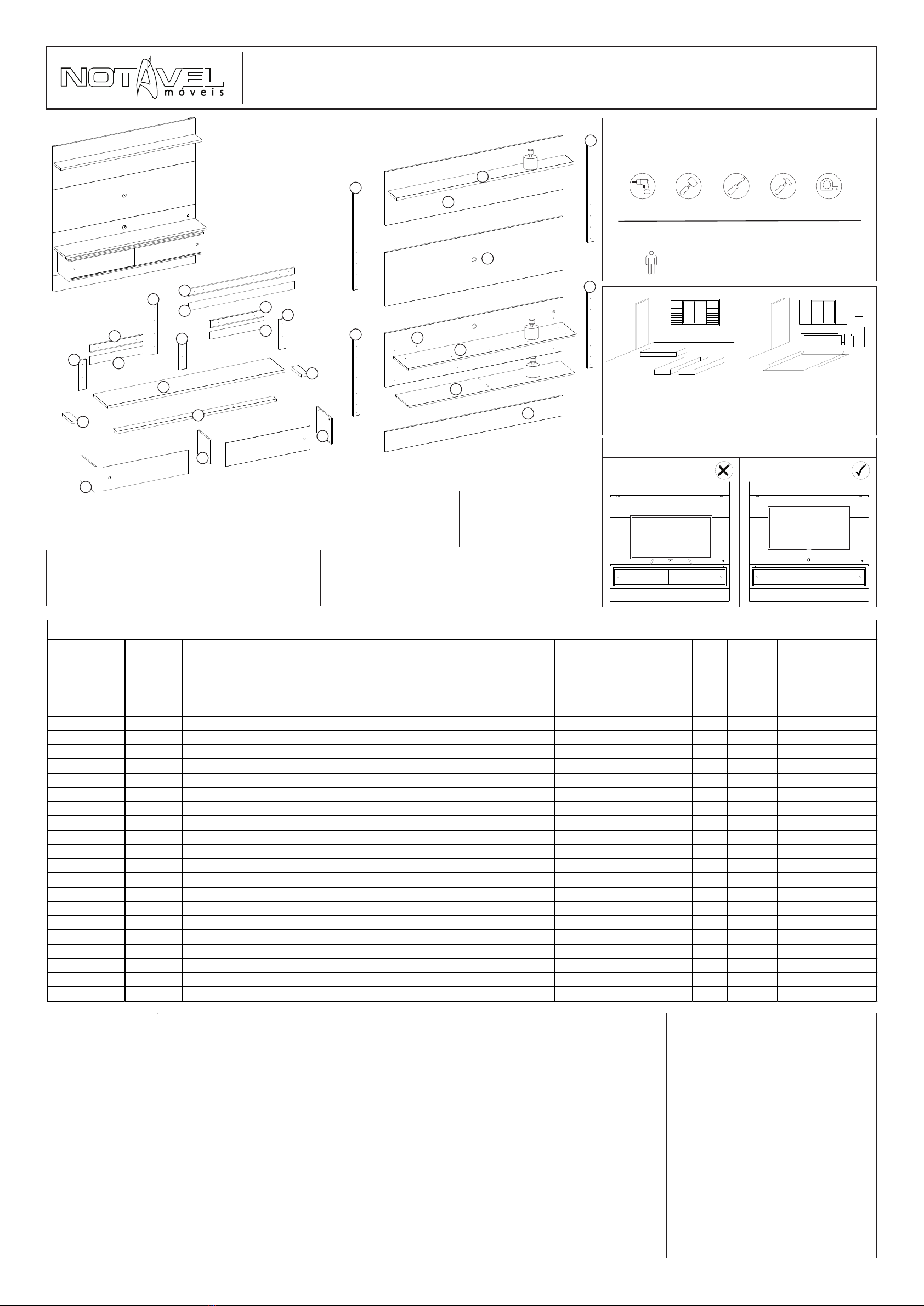
A TV deverá ser fixada no Painel. Não utilize a TV apenas apoiada sobre nicho.
ESQUEMA DE MONTAGEM
INSTRUCCIONES DE MONTAJE
ASSEMBLY INSTRUCTIONS
COD: NT 1200
PAINEL NT 1200
PANEL NT 1200
NT 1200 PANEL
DIMENSÕES TOTAIS | DIMENSIONES TOTALES |
: OVERALL DIMENSIONS
1808X1800X326 mm
VOLUME | VOLUMEN | VOLUME: 02
CAPACIDADE TV / CAPACIDAD TV / TV SIZE : 65'’
PÁGINA | PAGINA | PAGE: 01
CÓD PRODUTO
CÓD PRODUCTO
CODE
Nº PEÇA
NR. PIEZA
ITEM
DESCRIÇÃO
DESCRIPCIÓN
DESCRIPTION
MATERIAL
COD PEÇA
COD PIEZA
PART CODE
QTDE
CTD.
QTY.
COMP.
LARGO
LENGTH
LARG
ANCHO
WIDTH
ESP
ESP
THICK
NT1200 1 LATERAL ESQUERDA | LADO IZQUIERDO | LEFT SIDE MDP 43612-01 1 256 293 15
NT1200 2 BASE INFERIOR | BASE INFERIOR | BASE INFERIOR MDP 43613-02 1 1679 293 15
NT1200 3 DIVISORIA INFERIOR | PARTICIÓN INFERIOR | LOWER PARTITION MDP 43614-03 1 238 252 15
NT1200 4 LATERAL DIREITA | LADO DERECHO | RIGHT SIDE MDP 43615-04 1 256 293 15
NT1200 5 TAMPO NICHO | TAMPO NICHO | TOP NICHE MDP 43616-05 1 1714 295 15
NT1200 6 VISTA FRONTAL | VISTA FRONTAL | FRONT VIEW MDP 43617-06 1 1624 70 25
NT1200 7 VISTA LATERAL | VISTA LATERAL | SIDE VIEW MDP 43618-07 2 194 70 25
NT1200 8 TAMPO SUPERIOR | TAPA SUPERIOR | TOP TAMPO MDP 43619-08 1 1796 296 25
NT1200 22 PAINEL NICHO | PANEL NICHO | NICHO PANEL MDP 43932-22 1 1800 536 15
NT1200 10 SUPORTE 45° INF. PAREDE | SOPORTE DE PARED 45° INFERIOR | SUPPORT 45° BOTTOM WALL MDP 43621-10 2 540 78 15
NT1200 11 SUPORTE 45° INF. PAINEL | SOPORTE 45° PANEL INFERIOR | SUPPORT 45° BOTTOM PANEL MDP 43622-11 2 540 78 15
NT1200 12 PAINEL CENTRAL | PANEL CENTRAL | CENTER PANEL MDP 43623-12 1 1800 536 15
NT1200 23 PAINEL SUPERIOR | PANEL SUPERIOR | TOP PANEL MDP 43933-23 1 1800 536 15
NT1200 24 PRATELEIRA SUP | ESTANTE SUPERIOR | TOP SHELF MDP 43934-24 1 1796 173 25
NT1200 15 VISTA LATERAL SUPERIOR | VISTA LATERAL SUPERIOR | TOP SIDE VIEW MDP 43626-15 2 1008 71 15
NT1200 25 VISTA LATERAL INFERIOR | VISTA LATERAL INFERIOR | LOWER SIDE VIEW MDP 43935-25 2 800 71 15
NT1200 17 TRAVA | BLOQUEAR | LOCK MDP 43628-17 3 298 71 15
NT1200 18 SUPORTE TRAVA | GANCHO DE SUJECIÓN | LATCH BRACKET MDP 43629-18 1 540 71 15
NT1200 19 SUPORTE 45° SUP PAREDE | SOPORTE DE PARED 45° SUPERIOR | 45° TOP WALL BRACKET MDP 43630-19 1 1080 78 15
NT1200 20 SUPORTE 45° SUP PAINEL | SOPORTE DEL PANEL SUPERIOR A 45° | 45° TOP PANEL SUPPORT MDP 43631-20 1 1080 78 15
NT1200 26 PAINEL INFERIOR | PANEL INFERIOR | BOTTOM PANEL MDP 43936-26 1 1800 200 15
NT1200 21 KIT ACESSORIO | KIT DE ACCESORIOS | ACCESSORIES KIT - 43632-21 - - - -
RELAÇÃO DE PEÇAS | LISTA DE PIEZAS | PARTS LIST
5kg
5kg
5kg
05
22
02
26
12
23
24
15
15
25
25
07
07 06
03
04
01
08
17
17
17
11
10
10
11
20
19
18
LED
KIT LED
KIT LED
LED KIT
1
CÓDIGO:2652
CODIGO:2652
CODE:2652
RELAÇÃO DE FERRAGENS | LISTA DE HARDWARE | LIST OF HARDWARE
PÁGINA | PAGINA | PAGE: 02
A
CAVILHA MADEIRA 6x30mm
CLAVIJA MADERA 6x30mm
6x30mm WOODEN DOWEL
14
CÓDIGO:270
CODIGO:270
CODE:270
B
PARAFUSO MINIFIX 5x31mm
TORNILLO MINIFIX 5x31mm
5x31mm MINI-FIX SCREW
12
CÓDIGO:324
CODIGO:324
CODE:324
C
TAMBOR MINIFIX 12x9mm
BARRIL MINIFIX 12x9mm
12x9mm MINI-FIX BARREL
12
CÓDIGO:286
CODIGO:286
CODE:286
PD
PARAFUSO 4,5x60mm CABEÇA CHATA
TORNILLO 4,5x60mm CABEZA PLANA
4,5x60mm FLAT HEAD SCREW
21
CÓDIGO:11
CODIGO:11
CODE:11
PP
PARAFUSO 3,5x12mm CABEÇA CHATA
TORNILLO 3,5x12mm CABEZA PLANA
3,5x12mm FLAT HEAD SCREW
30
CÓDIGO:2202
CODIGO:2202
CODE:2202
BP
BUCHA PLÁSTICA 8mm
TACO PLASTICO 8mm
8mm PLASTC BUSHING
12
CÓDIGO:347
CODIGO:347
CODE:347
R
TAPA FURO ADESIVO 15mm
BOLSILLO ADHESIVO 15mm
ADHESIVE HOLE POCKET 15mm
8
CÓDIGO:119
CODIGO:119
CODE:119
AC
CAVILHA MADEIRA 8x20mm
CLAVIJA MADERA 8x20mm
8x20mm WOODEN DOWEL
4
CÓDIGO:897
CODIGO:897
CODE:897
W
PARAFUSO 3,5x25mm CABEÇA CHATA
TORNILLO 3,5x25mm CABEZA PLANA
3,5x25mm FLAT HEAD SCREW
38
CÓDIGO:2
CODIGO:2
CODE:2
Y
PARAFUSO 3,5x40mm CABEÇA CHATA
TORNILLO 3,5x40mm CABEZA PLANA
3,5x40mm FLAT HEAD SCREW
5
CÓDIGO:4
CODIGO:4
CODE:4
PM
PARAFUSO 6x70mm CABEÇA CHATA
TORNILLO 6x70mm CABEZA PLANA
6x70mm FLAT HEAD SCREW
12
CÓDIGO:1531
CODIGO:1531
CODE:1531
PS
PASSA FIO 46mm
PASA-CABLE 46mm
46mm THREAD GUIDE
2
CÓDIGO:1098
CODIGO:1098
CODE:1098
AN
CAVILHA MADEIRA 6x50mm
CLAVIJA MADERA 6x50mm
6x50mm WOODEN DOWEL
4
CÓDIGO:1498
CODIGO:1498
CODE:1498
SC
COLA SACHÊ 5 G
SOBRE DE COLA 5 G
COLA SACHET 5G
3
CÓDIGO:40
CODIGO:40
CODE:40
PV
PORTA DE VIDRO 3mm
PUERTA DE VIDRIO 3mm
GLASS DOOR 3mm
2
CÓDIGO:2295
CODIGO:2295
CODE:2295
T
PERFIL TRILHO 1679mm
PERFIL DE RIEL 1679mm
RAIL PROFILE 1679MM
2
CÓDIGO:2255
CODIGO:2255
CODE:2255
PASSO 01
PASO 01
STEP 01
1 - Insira as cavilhas A (6x30mm) nas peças 1, 2, 3, 4 e 8.
2 - Insira as cavilhas AN (6x50mm) na peça 24.
1 - Inserte los tornillos A (6x30mm) en las partes 1, 2, 3, 4 y 8.
2 - Inserte los tornillos AN (6x50mm) en la pieza 24.
1 - Insert the A bolts (6x30mm) in parts 1, 2, 3, 4, and 8.
2 - Insert the AN pegs (6x50mm) in part 24.
A 14
AN
A
A
24
AN 2
8
2
1
34
PASSO 02
PASO 02
STEP 02
1 - Fixe os minifix B (5x31mm) nas peças 1, 2, 4 e 5.
1 - Fije el minifix B (5x31mm) a las partes 1, 2, 4 y 5.
1 - Attach the minifix B (5x31mm) to parts 1, 2, 4, and 5.
B 12
PASSO 03
PASO 03
STEP 03
1 - Encaixe a peça 1 na peça 2. Encaixe os tambores minifix C
na peça 2 e gire até travar.
1 - Deslice la parte 1 en la parte 2. Introduzca los tambores
mini-fix C en la pieza 2 y gírelos hasta que encajen.
1 - Fit part 1 to part 2. Fit the minifix C drums into part 2 and
turn until they lock.
1
4
2
5
C 2
1
2
PASSO 04
PASO 04
STEP 04
1 - Encaixe a peça 3 na peça 2. Encaixe os tambores minifix C
na peça 3 e gire até travar.
1 - Deslice la parte 3 en la parte 2. Introduzca los tambores
mini-fix C en la pieza 3 y gírelos hasta que encajen.
1 - Fit part 3 to part 2. Fit the minifix C drums into part 3 and
turn until they lock.
C 2
2
3
PASSO 05
PASO 05
STEP 05
1 - Encaixe a peça 4 na peça 2. Encaixe os tambores minifix C
na peça 2 e gire até travar.
1 - Deslice la parte 4 en la parte 2. Introduzca los tambores
mini-fix C en la pieza 2 y gírelos hasta que encajen.
1 - Fit part 4 to part 2. Fit the minifix C drums into part 2 and
turn until they lock.
C 2
4
2
PASSO 06
PASO 06
STEP 06
1 - Passe cola SC em cima das peças 6 e 7 antes de
parafusar as mesmas.
2 - Insira as cavilhas AN na peça 5 transpassando-as nas
peças 6 e 8.
3 - Fixe os parafusos PD (4,5x60mm) transpassando as peças
5, 6 e 8.
4 - Em seguida alinhe a furação da peça 7 na furação da peça
a 5. Fixe as peças 5, 7 e 8 com os parafusos PD (4,5x60mm).
1 - Aplique cola SC en la parte superior de las piezas 6 y 7
antes de atornillarlas.
2 - Inserte los tornillos AN en la pieza 5 pasándolos a través
de las piezas 6 y 8.
3 - Fije los tornillos PD (4,5x60mm) a través de las piezas 5, 6
y 8.
4 - A continuación, alinee el taladro de la pieza 7 con el taladro
de la pieza 5. Fije las piezas 5, 7 y 8 con los tornillos PD
(4,5x60mm).
1 - Apply SC glue on top of parts 6 and 7 before screwing
them together.
2 - Insert the AN bolts in part 5 passing them through parts 6
and 8.
3 - Fasten the PD screws (4,5x60mm) passing through pieces
5, 6 and 8.
4 - Then align the drill of part 7 with the drill of part 5. Fix the
parts 5, 7 and 8 with the PD screws (4,5x60mm).
AN 2
PD 5
SC 1
PD
AN
87
6
5
7
PASSO 07
PASO 07
STEP 07
1 - Encaixe a peça 5 nas peças 1, 3 e 4. Encaixe os tambores
minifix C nas peças 1, 3 e 4 e gire até travar.
2 - Cole os adesivos R sobre os tambores C.
1 - Encaje la pieza 5 en las piezas 1, 3 y 4. Encaje los
tambores mini-fix C en las piezas 1, 3 y 4 y gírelos hasta que
encajen.
2 - Pega las pegatinas R en los tambores C.
1 - Assemble part 5 onto parts 1, 3 and 4. Assemble the minifix
drums C onto parts 1, 3 and 4 and rotate until they lock.
2 - Glue the R stickers on the C drums.
C 6
R 8
54
3
1
TM
SUPORTE METAL FIXAÇÃO 60x60mm
SUPORTE METAL FIJACIÓN 60x60mm
60x60mm METAL FIXING SUPPORT
5
CÓDIGO:1537
CODIGO:1537
CODE:1537
PÁGINA | PAGINA | PAGE: 03
PASSO 08
PASO 08
STEP 08
1 - Alinhe as peças 25 nas peças 22 e 26 e fixe-as com os
parafusos W (3,5x25mm).
2 - Fixe o suporte de metal TM entre as peças 22 e 26 com os
parafusos PP (3,5x12 mm).
1 - Alinee la pieza 25 con las piezas 22 y 26 y fíjelas con los
tornillos W (3,5x25mm).
2 - Fije el soporte metálico TM entre las piezas 22 y 26 con los
tornillos PP (3,5x12mm).
1 - Align the parts 25 on the parts 22 and 26 and fix them with
the screws W (3,5x25mm).
2 - Secure the TM metal bracket between parts 22 and 26 with
the PP screws (3,5x12mm).
W 12
TM 3
PP 12
PASSO 09
PASO 09
STEP 09
1 - Insira as cavilhas AC (8x20mm) nas peças 11. Em seguida
passe cola SC nas peças 11 e encaixe na peça 22.
2 - Encaixe a peça 22 nas cavilhas da peça 8 e fixe-as peças
11 na peça 22 com os parafusos PD (4,5x60mm) que irá
transpassar até a peça 8.
3 - Fixe a peça 22 na peça 8 com os parafusos PD
(4,5x60mm).
4 - Fixe a peça 22 na peça 2 com os parafusos Y (3,5x40mm).
1 - Inserte los tacos AC (8x20mm) en las piezas 11. Luego
pase un poco de cola SC en las piezas 11 y encaje la pieza
22.
2 - Insertar la pieza 22 en las espigas de la pieza 8 y fijar las
piezas 11 en la pieza 22 con los tornillos PD (4,5x60mm) que
pasarán por la pieza 8.
3 - Fijar la pieza 22 en la pieza 8 con los tornillos PD
(4,5x60mm).
4 - Fijar la pieza 22 en la pieza 2 con los tornillos Y
(3,5x40mm).
1 - Insert the dowels AC (8x20mm) in the pieces 11, then glue
the pieces 11 with SC glue and fit the piece 22.
2 - Fit the piece 22 on the pegs of the piece 8 and fix the
pieces 11 on the piece 22 with the PD screws (4,5x60mm) that
will go through to the piece 8.
3 - Fasten the part 22 on the part 8 with the PD screws
(4,5x60mm).
4 - Fasten the part 22 on the part 2 with the Y screws
(3,5x40mm).
PD 10
AC
26 22
25
25
22
8
11
11
PASSO 11
PASO 11
STEP 11
FIXAÇÃO DO NICHO NA PAREDE: 1- Se desejar que o
nicho fique a uma distância de 200 mm do chão, deverá
posicionar a peça 10 na parede e a uma distância de 638 mm
entre o chão e o começo da peça 10 como no desenho
abaixo.
2 - Passe a broca da furadeira pelos furos 5mm da peça 10 e
25 para marcar a parede, retire a peça 10 e 25 e insira as
buchas BP na parede.
3 - Fixe a peça 10 na parede com parafusos PM (6x70mm),
em seguida, encaixe o nicho no suporte da parede e fixe a
peça 25 com os parafusos PM (6x70mm).
FIJACIÓN DEL NICHO A LA PARED: 1- Si desea que la
hornacina se encuentre a una distancia de 200mm del suelo,
deberá colocar la pieza 10 en la pared y a una distancia de
638mm entre el suelo y el inicio de la pieza 10 como en el
dibujo inferior.
2 - Pase la broca por los orificios de 5 mm de las piezas 10 y
25 para marcar la pared, retire las piezas 10 y 25 e inserte los
tacos BP en la pared.
3 - Fije la pieza 10 en la pared con tornillos PM (6x70mm),
después, encaje el nicho en el soporte de la pared y fije la
pieza 25 con tornillos PM (6x70mm).
FASTENING THE NICHE TO THE WALL: 1- If you wish the
niche to find a distance of 200mm from the floor, you should
position piece 10 on the wall and at a distance of 638mm
between the floor and the start of piece 10 as in the drawing
below.
2 - Pass the drill bit through the 5mm holes of the piece 10
and 25 to mark the wall, remove the piece 10 and 25 and
insert the BP plugs in the wall.
3 - Fix the piece 10 on the wall with PM screws (6x70mm),
then fit the niche on the wall support and fix the piece 25 with
PM screws (6x70mm).
BP 8
PM
20 cm
63,8 cm
10
10
25
25
PAREDE
PARED
WALL PAREDE
PARED
WALL
PM 8
PASSO 10
PASO 10
STEP 10
1 - Passe os conectores do interruptor através do furo 23mm
da peça 22.
2 - Em seguida, encaixe o interruptor no furo da peça 22.
3 - Passe os conectores da luminiária através do furo indicado
com a letra B na peça 24.
4 - Encaixe a luminiária no furo indicado com a letra A na 24.
.1 - Pase los conectores del interruptor por el orificio de 23mm
de la pieza 22.
2 - A continuación, encaje el interruptor en el orificio de la
pieza 22.
3 - Pase los conectores de la luminaria por el orificio marcado
con una B en la pieza 24.
4 - Encaje la luminaria en el orificio indicado con la letra A en
el 24.
1 - Pass the switch connectors through the 23mm hole on part
22.
2 - Then fit the switch into the hole on piece 22.
3 - Pass the luminaire connectors through the hole indicated
with the letter B on the part 24.
4 - Fit the luminaire into the hole indicated with the letter A on
the 24.
22
PASSO 12
PASO 12
STEP 12
1 - Alinhe as peças 15 nas peças 12 e 23 e fixe-as com os
parafusos W (3,5x25mm).
2 - Fixe o suporte de metal TM entre as peças 12 e 23 com os
parafusos PP (3,5x12 mm).
1 - Alinee las piezas 15 sobre las piezas 12 y 23 y fíjelas con
los tornillos W (3,5x25mm).
2 - Fije el soporte metálico TM entre las piezas 12 y 23 con los
tornillos PP (3,5x12mm).
1 - Align the parts 15 on the parts 12 and 23 and fix them with
the screws W (3,5x25mm).
2 - Secure the TM metal bracket between parts 12 and 23 with
the PP screws (3,5x12mm).
W 16
TM 2
PP 8
W
W
12
23
15
15
PASSO 13
PASO 13
STEP 13
1 - Passe os conectores fixados na peça 24 pelo furo da 23.
2 - Encaixe a peça 24 na peça 23. Em seguida, passe cola SC
na peça 20 e encaixe a mesma na peça 23.
3 - Após encaixadas as peças 20 e 24 na peça 23. Fixe-as
com os parafusos PD (4,5x60mm).
4 - Fixe a peça 23 na peça 24 com os parafusos PD
(4,5x60mm).
1 - Pase los conectores fijados a la pieza 24 a través del
orificio de la pieza 23.
2 - Encajar la pieza 24 en la pieza 23. A continuación, pegar la
cola SC en la pieza 20 y encajarla en la pieza 23.
3 - Después de encajar las piezas 20 y 24 en la pieza 23.
Fíjelos con los tornillos PD (4,5x60mm).
4 - Fije la pieza 23 a la pieza 24 con los tornillos PD
(4,5x60mm).
1 - Pass the connectors attached to part 24 through the hole of
part 23.
2 - Fit part 24 to part 23. Then glue the SC glue on part 20 and
fit it to part 23.
3 - After the 20 and 24 are attached to the 23. Fix them with
the PD screws (4,5x60mm).
4 - Secure part 23 to part 24 with the PD screws (4,5x60mm).
INTERRUPTOR
1
LUMINÁRIA
2
24
A
B
SC 1
PD 6
24
23
20
PD
PD
PASSO 14
PASO 14
STEP 14
1 - Fixe-as peças 17 na peça 12 com os parafusos W
(3,5x25mm).
2 - Fixe-a peça 18 na peça 12 e 23 com os parafusos W
(3,5x25mm).
1 - Fije la pieza 17 en la pieza 12 con los tornillos W
(3,5x25mm).
2 - Fije la pieza 18 en las piezas 12 y 23 con los tornillos W
(3,5x25mm).
1 - Fasten part 17 on part 12 with the screws W (3,5x25mm).
2 - Fasten the part 18 on the part 12 and 23 with the screws W
(3,5x25mm).
W 10
W
12
23
18
17
17
17
PASSO 15
PASO 15
STEP 15
FIXAÇÃO DO PAINEL NA PAREDE: 1 - Posicione a peça
19 centralizada ao nicho na parede a uma distância de
760mm entre o final do painel 22 e o começo da peça 19
como no desenho abaixo.
2 - Passe a broca da furadeira pelos rasgos 6mm da peça 19
para marcar a parede, retire a peça 19 e insira as buchas BP
na parede.
3 - Em seguida fixe a peça 19 na parede com os parafusos
PM (6x70mm). Antes de encaixar o painel na parede conecte
os LEDS ao cabo de alimentação e ao interruptor, em seguida
encaixe o painel na parade.
FIJACIÓN DEL PANEL EN LA PARED: 1 - Colocar la pieza
19 centrada en la hornacina de la pared a una distancia de
760mm entre el final del panel 22 y el inicio de la pieza 19
como en el dibujo inferior.
2 - Pase la broca por las ranuras de 6 mm de la pieza 19 para
marcar la pared, retire la pieza 19 e inserte los tacos BP en la
pared.
3 - A continuación, fixe la pieza 19 a la pared con los tornillos
PM (6x70mm). Antes de instalar el panel en la pared, conecte
los LED al cable de alimentación y al interruptor y, a
continuación, instale el panel en la pared.
ATTACHING THE PANEL TO THE WALL: 1 - Position
piece 19 centered to the niche in the wall at a distance of
760mm between the final of the panel 22 and the beginning of
the piece 19 as in the drawing below.
2 - Pass the drill bit through the 6mm slots in piece 19 to mark
the wall, remove piece 19 and insert the BP plugs into the
wall.
3 - Then fixe the part 19 to the wall with the PM screws
(6x70mm). Before fitting the panel to the wall connect the
LEDS to the power cable and the switch, then fit the panel to
the wall.
BP 4
PM 4
PAREDE
PARED
WALL
76,0 cm
22
19
PM
PAREDE
PARED
WALL
19
2000mm
250mm
1000mm 1000mm
Fêmea
Fêmea
Macho
Macho Macho
RABICHO PARALELO 2X0,50MM
Fêmea
AC 4
SC 1
Y 5
Y
2
PÁGINA | PAGINA | PAGE: 04
PASSO 16
PASO 16
STEP 16
1 - Alinhe os trilhos T nas marcações das peças 2 e 5. Fixe os
parafusos PP (3,5x12mm) em somente três das cinco
marcações, igual está representado a baixo, e deixe duas das
marcações sem parafusar.
1 - Alinee los rieles en T con las marcas de las partes 2 y 5.
Fije los tornillos PP (3,5x12mm) sólo en tres de las cinco
marcas, como se muestra a continuación, y deje dos de las
marcas sin atornillar.
1 - Align the T rails on the markings of parts 2 and 5. Fix the
PP screws (3,5x12mm) on only three of the five markings as
shown below, and leave two of the markings unscrewed.
PP 6
TT 2
T
T
2
5
PASSO 17
PASO 17
STEP 17
1 - Como metade dos trilhos T não foi parafusada e está
flexível, assim, devemos puxar um pouco essa parte solta do
trilho para fora do nicho.
2 - Feito isso, iremos inserir e ir deslisando os vidros PV pelos
trilhos T até o final dos trilhos.
1 - Como la mitad de los raíles en T no estaban atornillados y
son flexibles, debemos tirar un poco de esta parte suelta del
raíl fuera del nicho.
2 - Una vez hecho esto, insertaremos y deslizaremos el
Acristalamiento PV a lo largo de los raíles T hasta el final de
los mismos.
1 - As half of the T-rails are unscrewed and flexible, we should
pull this loose part of the T-rail out of the niche.
2 - Once this is done, we will insert and slide the PV glass
through the T rails to the end of the rails.
PV 2
PV
PV
T
T
PASSO 18
PASO 18
STEP 18
1 - Deixe os dois vidros PV no lado que o trilho já está fixado,
assim, alinhe novamente ao nicho e fixe com os parafusos PP
(3,5X12mm) o lado dos trilhos que ainda estão soltos.
1 - Deje los dos vidrios PV en el lado que el riel ya está fijado,
entonces, alinee de nuevo al nicho y fije con los tornillos PP
(3,5X12mm) el lado de los rieles que aún están sueltos.
1 - Leave the two PV glasses on the side that the rail is
already fixed, so, align it again to the niche and fix with the PP
screws (3,5X12mm) the side of the rails that are still loose.
PP 4
PASSO 19
PASO 19
STEP 19
1 - Encaixe os passa fio PS nas peças 12 e 22.
1 - Coloque los ojales PS en las piezas 12 y 22.
1 - Attach the PS grommets to pieces 12 and 22.
PS 2
ACOMPANHE A NOTÁVEL MÓVEIS NAS REDES SOCIAIS.
SIGA EL NOTAVEL MOVEIS EN LAS REDES SOCIALES.
FOLLOW THE NOTAVEL MOVEIS ON THE SOCIAL NETWORKS
/NOTAVELMOVEIS @NOTAVELMOVEIS

Other Notável Móveis Indoor Furnishing manuals

Notável Móveis NT 2005 User manual

Notável Móveis

Notável Móveis NT 2005 User manual

Notável Móveis NT 1180 User manual

Notável Móveis

Notável Móveis NT 1180 User manual

Notável Móveis NT 1195 User manual

Notável Móveis

Notável Móveis NT 1195 User manual

Notável Móveis 55012 User manual

Notável Móveis

Notável Móveis 55012 User manual

Notável Móveis 56100 User manual

Notável Móveis

Notável Móveis 56100 User manual

Notável Móveis NT 1000 User manual

Notável Móveis

Notável Móveis NT 1000 User manual

Notável Móveis NT 4020 MULTIPURPOSE User manual

Notável Móveis

Notável Móveis NT 4020 MULTIPURPOSE User manual

Notável Móveis NT 1115 User manual

Notável Móveis

Notável Móveis NT 1115 User manual

Notável Móveis NT 5170 User manual

Notável Móveis

Notável Móveis NT 5170 User manual

Notável Móveis NT 1080 HOME User manual

Notável Móveis

Notável Móveis NT 1080 HOME User manual

Notável Móveis NT4010 User manual

Notável Móveis

Notável Móveis NT4010 User manual

Notável Móveis 55116 User manual

Notável Móveis

Notável Móveis 55116 User manual

Notável Móveis 52146 User manual

Notável Móveis

Notável Móveis 52146 User manual

Notável Móveis NT 3050 User manual

Notável Móveis

Notável Móveis NT 3050 User manual

Notável Móveis NT3075 User manual

Notável Móveis

Notável Móveis NT3075 User manual

Notável Móveis NT 1280 PANEL User manual

Notável Móveis

Notável Móveis NT 1280 PANEL User manual

Notável Móveis NT 3110 User manual

Notável Móveis

Notável Móveis NT 3110 User manual

Notável Móveis NT 5015 User manual

Notável Móveis

Notável Móveis NT 5015 User manual

Notável Móveis NT2050 User manual

Notável Móveis

Notável Móveis NT2050 User manual

Notável Móveis NT 5175 User manual

Notável Móveis

Notável Móveis NT 5175 User manual

Notável Móveis PAINEL NT 1115 User manual

Notável Móveis

Notável Móveis PAINEL NT 1115 User manual

Notável Móveis NT 2005 User manual

Notável Móveis

Notável Móveis NT 2005 User manual

Notável Móveis NT 3110 User manual

Notável Móveis

Notável Móveis NT 3110 User manual

Notável Móveis 51015 User manual

Notável Móveis

Notável Móveis 51015 User manual

Popular Indoor Furnishing manuals by other brands

HAMPTON BAY HARPER CREEK 725.0531.000 Assembly guide

HAMPTON BAY

HAMPTON BAY HARPER CREEK 725.0531.000 Assembly guide

Home Styles Monarch Kitchen Island 88 5020 941 Assembly instructions

Home Styles

Home Styles Monarch Kitchen Island 88 5020 941 Assembly instructions

agatameble NEVADA 2d4s Assembly instructions

agatameble

agatameble NEVADA 2d4s Assembly instructions

Moe's COLVIN SR-1030-24 Assembly instructions

Moe's

Moe's COLVIN SR-1030-24 Assembly instructions

Home Styles 5053-49 manual

Home Styles

Home Styles 5053-49 manual

SouthShore 4147-677 Assembly instructions

SouthShore

SouthShore 4147-677 Assembly instructions

NERI & HU 758 Assembly instructions

NERI & HU

NERI & HU 758 Assembly instructions

Twin Star Home OT6128 manual

Twin Star Home

Twin Star Home OT6128 manual

Happy Beds Chilton Ottoman Storage Bed 5ft Assembly instructions

Happy Beds

Happy Beds Chilton Ottoman Storage Bed 5ft Assembly instructions

HOMEDEPOT EMILY C-617 Assembly instructions

HOMEDEPOT

HOMEDEPOT EMILY C-617 Assembly instructions

Silver Fox 2246BN manual

Silver Fox

Silver Fox 2246BN manual

System Build 348487341COM9 manual

System Build

System Build 348487341COM9 manual

Home Styles 88 5318 95 Assembly instructions

Home Styles

Home Styles 88 5318 95 Assembly instructions

Polywood Quattro Adirondack Chair QLD200 Assembly instructions

Polywood

Polywood Quattro Adirondack Chair QLD200 Assembly instructions

System Build 7923414COM manual

System Build

System Build 7923414COM manual

3-form SimpleSpec 200.53-HooDoo installation manual

3-form

3-form SimpleSpec 200.53-HooDoo installation manual

Fromm&Starck STAR ATFE 05 user manual

Fromm&Starck

Fromm&Starck STAR ATFE 05 user manual

System Build 2484348COM Assembly instructions

System Build

System Build 2484348COM Assembly instructions

manuals.online logo
manuals.online logoBrands
  • About & Mission
  • Contact us
  • Privacy Policy
  • Terms and Conditions

Copyright 2025 Manuals.Online. All Rights Reserved.