manuals.online logo
Brands
  1. Home
  2. •
  3. Brands
  4. •
  5. Novus
  6. •
  7. Transmitter
  8. •
  9. Novus TxIsoRail0-10Vdc User manual

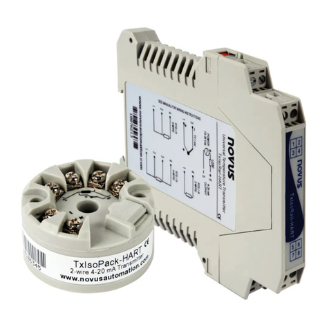
Novus TxIsoRail0-10Vdc User manual

INSTALLATION
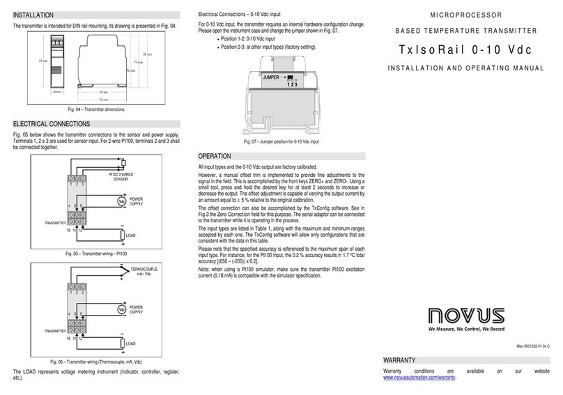
The transmitter is intended for DIN rail mounting. Its drawing is presented in Fig. 03.
Fig. 03 – Transmitter dimensions
ELECTRICAL CONNECTIONS
Fig. 04 below shows the transmitter connections to the sensor and power supply.
Terminals 1, 2 e 3 are used for sensor input. For 2-wire Pt100, terminals 2 and 3 shall
be connected together.
Fig. 04 – Transmitter wiring – Pt100
Fig. 05 – Transmitter wiring (Thermocouple, mA, Vdc)
The LOAD represents voltage metering instrument (indicator, controller, register,
etc.).
Electrical Connections – 0-10 Vdc input
For 0-10 Vdc input, the transmitter requires an internal hardware configuration change.
Please open the instrument case and change the jumper shown in Fig. 06.
Position 1-2: 0-10 Vdc input
Position 2-3: al other input types (factory setting).
Fig. 06 – Jumper position for 0-10 Vdc input
OPERATION
All input types and the 0-10 Vdc output are factory calibrated.
However, a manual offset trim is implemented to provide fine adjustments to the
signal in the field. This is accomplished by the front keys ZERO+ and ZERO-. Using a
small tool, press and hold the desired key for at least 2 seconds to increase or
decrease the output. The offset adjustment is capable of varying the output current by
an amount equal to 5 % relative to the original calibration.
The offset correction can also be accomplished by the TxConfig software. See in Fig.
02 the Zero Correction field for this purpose. The serial adaptor can be connected to
the transmitter while it is operating in the process.
The input types are listed in Table 1, along with the maximum and minimum ranges
accepted by each one. The TxConfig software will allow only configurations that are
consistent with the data in this table.
Please note that the specified accuracy is referenced to the maximum span of each
input type. For instance, for the Pt100 input, the 0.2 % accuracy results in 1.7 ºC total
accuracy [(650 – (-200)) x 0.2].
Note: when using a Pt100 simulator, make sure the transmitter Pt100 excitation
current (0.18 mA) is compatible with the simulator specification.
M I C R O P R O C E S S O R
B A S E D T E M P E R A T U R E T R A N S M I T T E R
T x I s o R a i l 0 - 1 0 V d c
I N S T A L L A T I O N A N D O P E R A T I N G M A N U A L
5001522 V1.0x E
www.GlobalTestSupply.com
Find Quality Products Online at: sales@GlobalTestSupply.com
SPECIFICATIONS
Sensor input: User defined. The supported sensors are listed in Table 01, along
with their maximum ranges.
Thermocouples: Types J, K, R, S, T, N, E and B, to IEC 60584 (ITS-90).
Impedance >> 1 M
Pt100: Excitation: 180 A, 2 or 3-wire connection (for 2-wire sensors,
tie terminals 2 and 3 together).
= 0.00385, according to IEC 60751 (ITS-90).
Voltage: 0 to 50 mVdc, 0 to 10 Vdc; Impedance: > 1 M
Current: 0 to 20 mAdc, 4 to 20 mAdc; Impedance: 15.0 (+ 1.9 Vdc)
Sensor Type Range
Minimum measurement span
Thermocouple K -150 to 1370 °C / -238 to 2498 ºF 100 °C
Thermocouple J -100 to 760 °C / -148 to 1400 ºF 100 °C
Thermocouple R -50 to 1760 °C / -58 to 3200 ºF 400 °C
Thermocouple S -50 to 1760 °C / -58 to 3200 ºF 400 °C
Thermocouple T -160 to 400 °C / -256 to 752 ºF 100 °C
Thermocouple N -270 to 1300 °C / -454 to 2372 ºF 100 °C
Thermocouple E -90 to 720 °C / -130 to 1328 ºF 100 °C
Thermocouple B 500 to 1820 °C / 932 to 3308 °F 400 °C
Pt100 -200 to 600 °C / -328 to 1112 ºF 40 °C
Voltage 0 to 50 mV 5 mV
0 to 10 V 1 V
Current 0 to 20 mA 2 mA
4 to 20 mA 2 mA
Table 01 – Transmitter input sensors
Output: 0 to 10 Vdc, linear with respect to the measured temperature.
Resolution: 0.0006 V (14 bits)
Maximum Current (Load): 2 mA
Total Accuracy: 0.25 % of the maximum span for thermocouples, 1 °C;
0.15 % for Pt100, mA and voltage (for voltage output above 100 mV).
Response Time: < 500 ms
Power Supply: 18 to 30 Vdc
Operating Temperature: -40 to 85 °C
Humidity: 0 to 90 % UR
Eletromagnetic Compatibility: EN 50081-2, EN 50082-2
Isolation between the sensor and the 4-20 mA loop (1000 V / 1 min).
Internal protection against polarity inversion.
Cold junction compensation for thermocouples.
Housing: ABS plastic. Dimensions: Refer to Fig. 03.
Certifications: CE, UKCA.
CONFIGURATION
If the transmitter is already configured as required by the application (sensor type,
range, etc), it may be installed and used right away. However, if a distinct
configuration is required, this can be done through the TxConfig software and the
TxConfig Interface.
The TxConfig Interface and Software can be purchased separately one of its
distributors. The latest release of this software can be downloaded from our web site.
Do not save the TxConfig software into a file which contains accent marks. To install,
run the Tx_setup.exe and follow the instructions. To install the configurator, run the
Tx_setup.exe file.
The TxConfig interface connects the transmitter to the PC, as shown in Fig. 01.
Fig. 01 – TxConfig Interface USB connections
Once the connection is accomplished, the software shows the configuration options
of the transmitter model attached. Access the Help for usage instructions.
The TxConfig screen in shown in Fig. 02.
Fig 02 – TxConfig main screen
The fields in the screen mean:
1. Sensor Input: Choose the desired temperature sensor among the available
options. See Table 01.
2. Measuring Range: Defines the output scale for the input sensor. Program here
the measurement Lower Range Value and the Upper Range Value.
When the Lower Range Value is configured with a value higher than the Upper
Range Value the voltage output swings from 10 to 0 V.
The values configured in these fields can not be beyond the sensor measuring
range. The minimum span value has to be observed as well (see Table 01).
3. Line Noise Rejection: The transmitter incorporates a digital filter to cancel the
induced noise from the 50 or 60 Hz systems. For better performance, select the
line frequency used in your country.
4. Sensor Failure Detection: Establishes the transmitter output behavior (upscale or
down-scale) in the presence of a sensor fail..
5. Zero Correction: Allows for small sensor corrections.
6. Device Information: The Device Information box contains relevant data
concerning a particular transmitter. Please pass along this information when
contacting the technical assistance department.
7. Apply: Sends a new configuration to the transmitter.
8. Read Configuration: Brings to the screen the Transmitter parameters
configuration.
Note: The factory default configuration is (unless otherwise specified or ordered):
Pt100 input, 0 to 100 °C
60 Hz filtering and upscale (20 mA) output for sensor fail.
During the configuration, the transmitter requires to be powered. Depending on the
PC used, the power can be supplied by the serial port. To assure proper
communication, it is recommended to apply external power to the transmitter.
The TxConfig interface has a complex electronic circuit. D
o not use any
other interface or cable connection to USB
; the product will be damaged
and this damage is not covered under warranty.
It is important to follow the recommendations below
Signal wires should be installed in grounded conduits and away from power or
contactor wires.
The instrument should have its own power supply wires, which should not be
shared with electrical motors, coils, contactors, etc.
Installing RC filters is strongly recommended at contactor coils or any other
inductors.
System failure should always be taken into account when designing a control
panel to avoid irreversible damage to equipment or people.
www.GlobalTestSupply.com
Find Quality Products Online at: sales@GlobalTestSupply.com
Other Novus Transmitter manuals

Novus TxIsoRail User manual

Novus

Novus TxIsoRail User manual

Novus RHT-WM-485-LCD User manual

Novus

Novus RHT-WM-485-LCD User manual

Novus NP785 User manual

Novus

Novus NP785 User manual

Novus TxRail User manual

Novus

Novus TxRail User manual

Novus TxIsoBlock-HRT User manual

Novus

Novus TxIsoBlock-HRT User manual

Novus RHT-WM-485-LCD User manual

Novus

Novus RHT-WM-485-LCD User manual

Novus RHT-XS User manual

Novus

Novus RHT-XS User manual

Novus TxIsoRail-HRT User manual

Novus

Novus TxIsoRail-HRT User manual

Novus RHT-Air User manual

Novus

Novus RHT-Air User manual

Novus NP600 User manual

Novus

Novus NP600 User manual

Novus TXRAIL Series User manual

Novus

Novus TXRAIL Series User manual

Novus TxIsoRail-HRT User manual

Novus

Novus TxIsoRail-HRT User manual

Novus RHT-WM User manual

Novus

Novus RHT-WM User manual

Novus TXMINI-M12-485 User manual

Novus

Novus TXMINI-M12-485 User manual

Novus NP620 User manual

Novus

Novus NP620 User manual

Novus TxBlock-USB User manual

Novus

Novus TxBlock-USB User manual

Novus RHT Climate WM User manual

Novus

Novus RHT Climate WM User manual

Novus TxRail User manual

Novus

Novus TxRail User manual

Novus TXMINI-DIN43650 User manual

Novus

Novus TXMINI-DIN43650 User manual

Novus TxBlock-USB User manual

Novus

Novus TxBlock-USB User manual

Novus NV-202VIP User manual

Novus

Novus NV-202VIP User manual

Novus TxRail-USB User manual

Novus

Novus TxRail-USB User manual

Novus TxRail-USB User manual

Novus

Novus TxRail-USB User manual

Novus NP785 User manual

Novus

Novus NP785 User manual

Popular Transmitter manuals by other brands

Seneca K120RTD installation manual

Seneca

Seneca K120RTD installation manual

Nautel GV40 installation manual

Nautel

Nautel GV40 installation manual

HumanTechnik cm-light operating instructions

HumanTechnik

HumanTechnik cm-light operating instructions

INOR APAQ C130 TC User instructions

INOR

INOR APAQ C130 TC User instructions

Linear DXS-64 operating instructions

Linear

Linear DXS-64 operating instructions

FeinTech ABT00102 instruction manual

FeinTech

FeinTech ABT00102 instruction manual

Geo Web Pack quick start guide

Geo

Geo Web Pack quick start guide

Inovonics EchoStream EN1210W installation instructions

Inovonics

Inovonics EchoStream EN1210W installation instructions

IKONNIK KA-6 quick start guide

IKONNIK

IKONNIK KA-6 quick start guide

Rohde & Schwarz SR8000 Series System manual

Rohde & Schwarz

Rohde & Schwarz SR8000 Series System manual

Audio Technica UniPak ATW-T93 Installation and operation

Audio Technica

Audio Technica UniPak ATW-T93 Installation and operation

NIVELCO EasyTREK SCA-300 Series Programming manual

NIVELCO

NIVELCO EasyTREK SCA-300 Series Programming manual

Honeywell 5816WMBR installation instructions

Honeywell

Honeywell 5816WMBR installation instructions

Kamstrup READy MTU Installation and operation guide

Kamstrup

Kamstrup READy MTU Installation and operation guide

Omega ZW Series user guide

Omega

Omega ZW Series user guide

ABB Field 264H Instructions for installation

ABB

ABB Field 264H Instructions for installation

Dejero EnGo 3x manual

Dejero

Dejero EnGo 3x manual

Rosemount 4600 Reference manual

Rosemount

Rosemount 4600 Reference manual

manuals.online logo
manuals.online logoBrands
  • About & Mission
  • Contact us
  • Privacy Policy
  • Terms and Conditions

Copyright 2025 Manuals.Online. All Rights Reserved.