NUVE NF 200 User manual

NÜVE SANAYİ MALZEMELERİ İMALAT VE TİCARET A.Ş.
Z14.K25.249 REV.NO.:10 REV.DATE:01/2018
NF200
BENCH TOP CENTRIFUGE
USER’S MANUAL

1
MANUFACTURER
NÜVE SANAYİ MALZEMELERİ İMALAT VE TİCARET A.Ş.
Saracalar Mah. Saracalar Kümeevleri No: 4/2
Akyurt 06750 Ankara
TEL: +(90) 312 399 28 30 (pbx)
FAX: +(90) 312 399 21 97
E-mail:satis@nuve.com.tr
WARRANTY CERTIFICATE
1. Nüve warrants that the equipment delivered is free from defects during material and
workmanship. This warranty is provided for a period of two years. The warranty period
begins from the delivery date.
2. Warranty does not apply to parts normally consumed during operation or general
maintenance or any adjustments described in the operating instructions provided with
the equipment.
3. Nüve does not accept any liability in the case where the goods are not used in
accordance with their proper intent.
4. The warranty may not be claimed for damages occurred during the shipment, for
damages resulting from improper handling or use, the defects in maintenance,
negligence, bad functioning of auxiliary equipment, in the case of force majeure or
accident and incorrect power supply.
5. In the event of failure, Nüve shall be under no liability for any injury, or any loss or
damage as the result of the failure other than the guarantee conditions.
•BEFORE OPERATING THE INSTRUMENT THIS MANUAL SHOULD BE READ
CAREFULLY.
•THE VALIDITY OF THE GUARANTEE IS SUBJECT TO THE OBSERVATION OF
THE INSTRUCTIONS AND PRECAUTIONS DESCRIBED IN THIS MANUAL.
•INFORMATION CONTAINED IN THIS DOCUMENT IS THE PROPERTY OF NÜVE. IT
MAY NOT BE DUPLICATED OR DISTRIBUTED WITHOUT PERMISSION.

2
DEAR NUVE USER
We would like to take this opportunity to thank you for preferring this Nüve product. Please
read the operating instructions carefully and keep them handy for future reference.
Please detain the packing material until you see that the unit is in good condition and it is
operating properly. If an external or internal damage is observed, contact the transportation
company immediately and report the damage. According to ICC regulations, this
responsibility belongs to the customer.
While you are operating the instrument please;
•obey all the warning labels,
•do not remove the warning labels,
•do not operate damaged instrument,
•do not operate the instrument with a damaged cable,
•do not move the instrument during operation.
In case of a problem contact your Nüve agent for an authorized service or maintenance.
The validity of the guarantee is subject to compliance with the instructions and precautions
described in this manual.
Nüve reserves the right to improve or change the design of its products without any
obligation to modify previously manufactured products.
Information contained in this document is the property of Nüve. It may not be duplicated or
distributed without its permission.
PLEASE REGISTER ONLINE TO VALIDATE WARRANTY:
To register your warranty online, please visit our web page www.nuve.com.tr and fill in WARRANTY
REGISTRATION FORM.

3
TABLE OF CONTENTS
SECTION 1 –INTRODUCTION.............................................................................................................. 4
1.1. USE AND FUNCTION............................................................................................................. 4
SECTION 2 –TECHNICAL SPECIFICATIONS...................................................................................... 5
2.1. TECHNICAL SPECIFICATIONS TABLE................................................................................. 5
2.2. ACCESSORIES FOR NF200.................................................................................................. 5
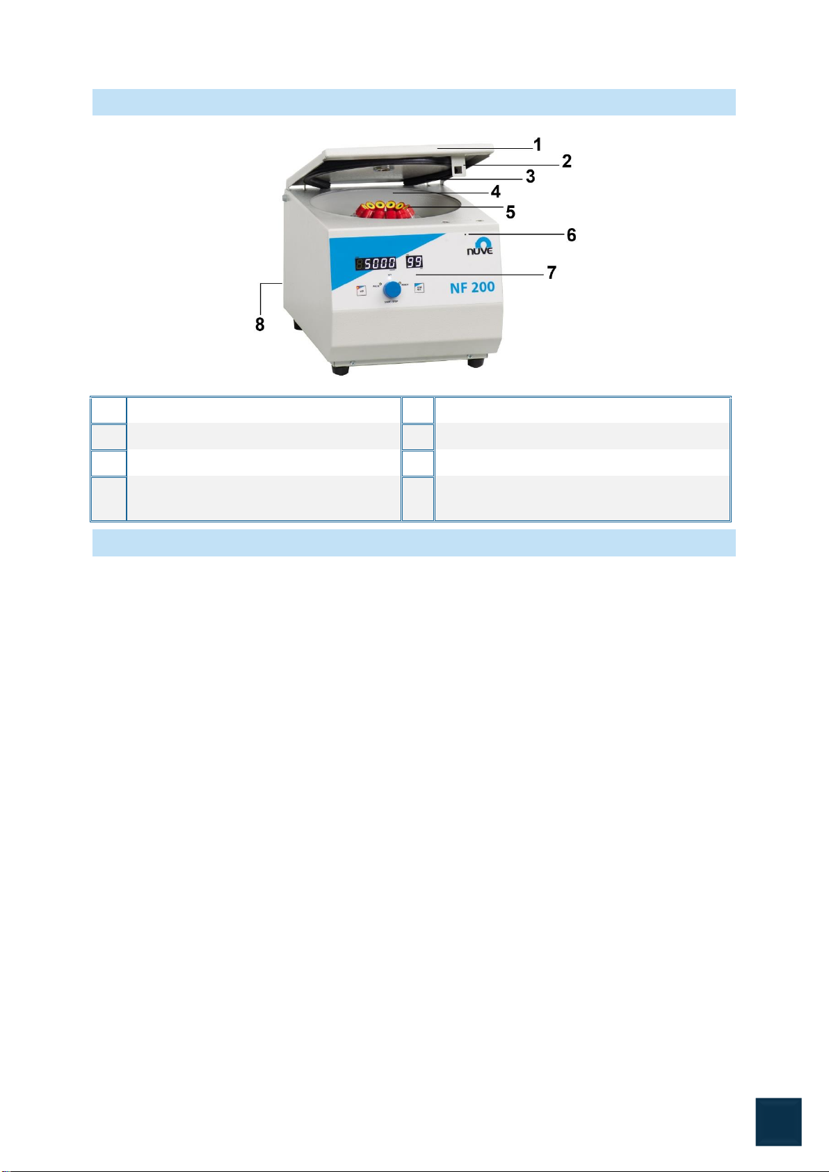
2.3. GENERAL PRESENTATION .................................................................................................. 6
2.4. RECAUTIONS AND USAGE LIMITATIONS........................................................................... 6
SECTION 3 –SYMBOLS........................................................................................................................ 7
SECTION 4 –INSTALLATION................................................................................................................ 7
4.1. LIFTING AND TRANSPORT................................................................................................... 7
4.2. UNPACKING ........................................................................................................................... 7
4.3. POSITIONING......................................................................................................................... 7
4.4. MAIN SUPPLY......................................................................................................................... 8
SECTION 5 –OPERATING UNIT........................................................................................................... 8
5.1. OPERATING............................................................................................................................ 8
5.2. DISPLAY AND CONTROL PANEL ......................................................................................... 8
5.3. MAKING PROGRAM............................................................................................................... 9
5.3.1 PULSE MODE................................................................................................................... 10
5.4 SAFETY INTERLOCK SYSTEM........................................................................................... 11
5.5 MANUAL LID OPENING ....................................................................................................... 11
SECTION 6 –OPERATING PRINCIPLES............................................................................................ 12
6.1 PREPARATION OF THE ROTOR TO RUN.......................................................................... 12
6.2 LOADING............................................................................................................................... 12
6.3 DRIVE SYSTEM.................................................................................................................... 13
SECTION 7 –CLEANING AND PERIODIC MAINTENANCE............................................................... 13
7.1 PERIODIC MAINTENANCE.................................................................................................. 13
7.2 STERILIZATION.................................................................................................................... 13
7.3 CORROSION INFORMATION .............................................................................................. 13
7.4 CLEANING ............................................................................................................................ 14
7.5 ELECTRICITY ....................................................................................................................... 14
SECTION 8 –DISPOSAL MANAGEMENT CONCEPT........................................................................ 14
BÖLÜM 9 –TROUBLESHOOTING ...................................................................................................... 15
SECTION 10 –ELECTRICAL CIRCUIT DIAGRAMS ........................................................................... 16
SECTION 11 –WARNING LABEL........................................................................................................ 17

4
SECTION 1 –INTRODUCTION
1.1. USE AND FUNCTION
NF 200 Bench Top Centrifuge is especially designed for the separation of blood samples,
sedimentation of urine particles and for the separation of substance or substance mixtures in
laboratories.
By means of the programmable microprocessor control system, speed, RCF value and time
could be programmed and the ‘pulse’ function allows the operator to run short spins.
NF 200 ensures safe operation by means of the locking system which does not allow the
centrifuge to operate if the lid is open the lid cannot be opened while the rotor is spinning.
There are audible and visible alarms to inform the operator when the lid is open, when the
program ends and when any error condition occurs. In case of a power failure, the lid could
be opened manually by using a manual lid opening tool. There is also an observation hole on
the lid to check the speed of the centrifuge by a tachometer.
NF 200 is delivered with 12x15 ml angle rotor made of polypropylene.
NF 200 Bench Top Centrifuges are manufactured according to the following
standards,
EN 61010-1, EN 61010-2-020, EN 61000-6-3, EN 50419, EN 61326-1.
This device is in compliance with WEEE Regulation.

5
SECTION 2 –TECHNICAL SPECIFICATIONS
2.1. TECHNICAL SPECIFICATIONS TABLE
Technical Specifications
NF 200
Maximum speed
5.000 rpm
Maximum RCF
2.822xg
Tube capacity
12 x 15 ml
Control system
Programmable Microprocessor Control System
Speed set range
1.000-5.000 rpm
Speed set step
10 rpm
Timer set range
1-99 min. and hold position
Timer set step
1 minute
Motor
Induction Motor
Power Supply
230 V, 50/60 Hz
Power Consumption
150 W
External Dimensions (WxDxH)
mm.
280x360x260
Packet Dimensions (WxDxH)
mm.
350x420x460
Net / Packed weight (kg)
12/16
2.2. ACCESSORIES FOR NF200
G 03 012
Adaptor for 1.5/2 ml tubes, max tube dia 11 mm
G 03 014
Adaptor for 7 ml vacuumed/ non vacuumed tubes, max tube dia 13 mm
G0 3 015
Adaptor for 5 ml vacuumed/ non vacuumed tubes, max tube dia 13 mm

6
2.3. GENERAL PRESENTATION
1
LID
5
Rotor
2
Lock pin
6
Manual LİD opening hole
3
Lid Gasket
7
Control panel
4
Bowl
8
Electrıcal cables inlet, On / off switch and
fuses
2.4. RECAUTIONS AND USAGE LIMITATIONS
•Do not use the device for any purpose other than the usage purpose.
•Prior to first use, the user’s manual should be read and the device is only to be used by
authorized and trained personnel. Only authorized technical personnel handle the
product in case of any failure.
•The working bench should be durable to the device weight and vibration isolated.
•Ensure that the rotor is placed correctly prior to usage.
•According to the standard IEC 61010-2-020, anyone and any hazardous materials
should not be in the 300 mm safety zone while centrifuge is running.
•Do not move the device while it is running.
•Do not open the lid while rotor is spinning.
•Apply the manual lid opening procedure in the case of power cut or in the case of any
error.
•Use only the the spare parts, rotors and accessories which are supplied by NUVE.
•Load the rotor according to the explanations in the user’s manual.
•Start the device after ensuring the rotor is loaded correctly.
•Do not use the centrifuge in areas which are in explosive danger.
•Do not centrifuge the explosive, flammable, radioactive, corrosive materials and the
materials which may react with each other.
•The centrifuge and the rotor are not microbiologically leak-proof. Use tubes with leak-
proof covers, if hazardous, toxic and pathogenic microorganisms are centrifuged.
•Do not use corrosive materials which may be harmful for the device integrity, rotor and
accessories.
•Do not use rotors and accessories with corrosion and mechanical damages.
•Mains supply should be appropriate to power of the device and grounded.
•Use tubes whose sizes are suitable to the rotor and accessories.
•Tubes which are used in the centrifuge should not be deformed by the effect of the
centrifuge force.

7
•Use glass tubes to balance, if glass tubes are used. Use plastics tubes to balance, if
plastics tubes are used.
•Do not start the device unless tubes are in balance.
•Imbalance loading may cause mixing the samples, broken tubes, and damages on the
rotor and motor shaft.
SECTION 3 –SYMBOLS
SECTION 4 –INSTALLATION
4.1. LIFTING AND TRANSPORT
Because of the heavy weight of the centrifuge, all lifting and transport must be carried out
using proper handling equipment. The centrifuge should be lifted from underneath and never
be turned over.
4.2. UNPACKING
Remove the packing cardboard box and the second nylon packing around the centrifuge.
The below written are provided with the instrument, please check them;
•1 ea. User’s manual
•1 ea. Warranty certification
•1 ea. Power cable
•1 ea. Manual lid opening tool
4.3. POSITIONING
•Check that no damage has occurred during transport.
•Check that the positioning is suitable for users.
•Lift the centrifuge (use proper handling equipment if necessary) underneath and carry it
to its place. Check that the centrifuge is stable on its four pads.
•The bench-top must be rigid enough to support the weight and vibrations.
•Leave 30 cm. free space on the every side of the centrifuge.
•Open the lid by using unlocking tool and check no substances left in the bowl.
•Make sure that the centrifuge does not occupy the utilization space of nearby
equipment or do damage to them.
•The user should be able to follow the centrifuge during the operation.
If mentioned warnings are not considered, nüve will not be responsible
from their results.
Symbol in the operating instructions: Attention, general hazard area.
This symbol refers to safety relevant warnings and indicates possibly
dangerous situations. The non-adherence to these warnings can lead to
material damage and injury to personal.
Symbol in the operating instructions: This symbol refers to important
circumstances.

8
4.4. MAIN SUPPLY
The centrifuge requires 230 V, 50 / 60 Hz. Please make sure that the supplied mains match
the required power ratings. If no, provide an extra line to support.
SECTION 5 –OPERATING UNIT
5.1. OPERATING
•Open the lid and check that there is no sample in the instrument.
•Turn the centrifuges on by using On/Off switch.
•See that the display and control panel activates.
•Learn the functions of the control panel.
•Set the values and start the operation.
5.2. DISPLAY AND CONTROL PANEL
According to the standard IEC 61010-2-020, anyone and any
hazardous materials should not be in the 300 mm safety zone while
centrifuge is running.
The centrifuges are designed to operate safely under the following
conditions:
- Indoor use only
- Ambient temperature: 5 °C to 25 °C.
- Maximum relative humidity of 80% for temperature up to 22 °C.
- Maximum altitude: 2000 m.
- Temperature for maximum performance: 15 °C / 25 °C.
Always plug the sterilizer/ovens to properly earthed sockets.
A supply fitted with a circuit breaker should be used for protection
against indirect contact in case of an insulation fault.

9
01- Status Display
This display shows the speed values (RPM or RCF) during programming. It also indicates
accelerating condition, braking condition, power failure condition, open lid condition and the
condition that occurs when Start is pressed while the lid is open by the expressions Acc, br,
E oFF, oPEn, cLoSE Lid, respectively. The error codes that occur in case of any failure
condition are also shown on this display.
02- Time Display
Display of the run time from 1 min. to 99 min. and hold position (H).
03- LID Key
Opens the lid if the lid indicator lights up
04- LID Indicator Led
It turns on if the lid remains open or is not properly closed.
05- ENCODER Button
This has two functional move. Turn clockwise and opposite clockwise, reach program menu,
set value and “READY” situation. By turning the Encoder button increase or decrease values
during programming stage. When Led is “READY” situation, by pushing Encoder button start
device. Stops the run by starting the braking phase manually.
06- READY Led
It indicates that the device ready to run.
07- RPM/RCF Key
Check the RPM or RCF value during the operation.
08- PULSE Led
It indicates that the user is on the program menu.
09- Set Menu Led
It indicates that the user is on the set value menu.
5.3. MAKING PROGRAM

10
Determine the rotor type, the speed and time, the acceleration and braking rates.
•Load the rotor with samples by paying attention to the dynamic and static balances.
•Set the all parameters for program.
•Close the lid, see that the lid open warning led turns off.
•Push the Encoder button.
5.3.1 PULSE MODE
•Load the rotor with samples by paying attention to the dynamic and static balances.
•Set the all parameters for program.
•Close the lid, see that the lid open warning led turns off.
•You can reach the desired speed by pressing and holding the Encoder button (6) within
the RPM speed limits you have set.
•In the PULSE mode, the rotor operates according to the set acceleration and braking
values you set.
•While operating in Pulse mode, press the Encoder button (6) and start counting from
the moment the rotor starts to accelerate. When you take your hand out of the Encoder
button, it will stop counting by braking.
The correct rotor type should be selected in order to see the correct
RCF values during the run.

11
5.4 SAFETY INTERLOCK SYSTEM
The safety interlock system prevents opening of the lid when the rotor is spinning.
The centrifuge does not operate until the lid is closed and the lid remains locked until the
rotor stops spinning. The “Lid Open” indicator turns on to warn the user if the lid is not closed
properly.
5.5 MANUAL LID OPENING
In case of a power cut or any defects, the instrument would be opened manually to be able to
get the samples.
To open the lid manually :
•Power off the instrument
•Insert the manual lid opening tool into the hole at the front side of the instrument.
•Push the tool while keeping it vertically until the lid is opened.
•After opening the lid manually, turn off and on device.
You may display the RPM or RCF value on the speed display during
the run by pushing the function button.
The centrifuge waits at the stand-by position with the program values of
the last program.
Please open the lid after every operation, otherwise the centrifuge
cannot be run again.
If power failure occurs, access to the samples is possible by opening
the lid with a special tool. Please see the manual lid opening section for
further information.
Before opening the lid manually, make sure that the rotor already
stopped spinning. Upon opening the lid, lift it by hand and observe the
rotor. If the rotor is still spinning, close the lid and wait approximately
10 minutes before repeating the operation. This operation must be
carried by someone who is informed of the danger and of the
precautions which must be undertaken.
After opening the lid manually, turn off and on device.

12
SECTION 6 –OPERATING PRINCIPLES
6.1 PREPARATION OF THE ROTOR TO RUN
Before installation, check the rotor for corrosion and cleanliness.
Chemical corrosion or mechanical corrosion may do severe damage to the rotor and the
centrifuge. Particles which are stuck inside the inserts cause the breakage of tubes and lead
to major imbalance please check to make sure that no particles are left on the rotor.
The central hole of the rotor and the motor shaft should also be clean and dry before all
centrifugal operations and they must be kept in that way all the time.
6.2 LOADING
•Each tube insert must be at the same weight as the one diametrically opposite for
balancing.
•In case the number of tubes which will be centrifuged is less than the capacity of the
rotor, the tubes must be placed in opposite inserts. If the number of tubes that will be
centrifuged is an odd number, use a water-filled tube at the same weight for balancing.
Examples of the proper and improper loading are shown below.
Figure 1
Imbalance of the rotor may cause major damage to the rotor and
centrifuge.
Never attempt to introduce liquids into the tube inserts.
Balance the rotor with glass tubes if you use glass tubes for
centrifugation.
Balance the rotor with plastic tubes if you use plastic tubes for
centrifugation.
Always use tubes which can withstand to the set speeds.

13
6.3 DRIVE SYSTEM
•The rotor is driven by a three phase asynchronous motor. The microprocessor control
system assures the correct drive speed.
•The force applied to the rotor is directly related to the shape of the rotor, the swing-out
rotor receives more load than the angle rotor does. Longer radius and more
accessories increase the load of the rotor and decrease the spinning speed.
•The centrifuge does not allow the rotor to spin at a speed which it cannot resist
mechanically.
•Please make that sure the correct type of rotor is selected during programming.
SECTION 7 –CLEANING AND PERIODIC MAINTENANCE
7.1 PERIODIC MAINTENANCE
•Disconnect the power cable and after the maintenance check the presence of the
mains grounding line.
•Rotors should be washed after every use, especially if a spillage has occurred, in warm
water containing a few drops of liquid soap. (A mild washing liquid is ideal as a
cleaner).
•Rotors and other accessorıes must be clean if any spillage or chemicals occur.
•You may use a nylon brush to clean the buckets and tube inserts of the rotor.
•Do not use metal brushes.
•Dry the rotor with a piece of soft absorber cloth. Please make sure that the buckets and
inserts are well dried, you may use hair dryer.
•The buckets of the swing-out rotors should be greased frequently with the oil provided
with the centrifuge. Please remove the light oil from the pins and put a small amount of
fresh oil every time you grease. This will ensure free swinging of the buckets. Most of
the imbalance problems are mostly raised by the users who do not clean and oil the
pins.
•Please do not leave the rotor on a metal surface, particularly stainless steel as
electrochemical reactions set off easily with the aluminum or magnesium in the rotor.
•Make sure that no deposit remains at the bottom of the bucket because the pressure of
a flask or tube from above during centrifugation will certainly increase the chance of
corrosion.
7.2 STERILIZATION
•Apply alcohol, for example %70 ethanol or isoprophanol, for 10 minutes against
bacteria and viruses.
•The rotors and buckets may be autoclaved at 121°C and under 215 kPa pressure for
20 minutes but please do not forget to remove all accessories.
•Do not use formaldehyde for the sterilization process.
•Phenol is a corrosive substance and should never be used.
•Glutaraldehyde is a toxic substance and increases the rate of fatty acid in the body.
7.3 CORROSION INFORMATION
•Nuve rotors which are made of aluminum are designed to spin at proper RCFs for
many years. When used properly, their resistance to corrosion and their life span
increases and the imbalance problems decrease.
•All accessories should be checked thoroughly and regularly as almost all laboratories
already have the conditions which lead to corrosion easily.

14
7.4 CLEANING
•Disconnect the centrifuge before cleaning.
•There is no need of daily cleaning unless a tube breakage occurs or any liquid spills.
7.5 ELECTRICITY
Centrifuged at high voltages are present behind the panels. These panels are electrically
disconnecting Do not open the centrifuge.
SECTION 8 –DISPOSAL MANAGEMENT CONCEPT
The currently valid local regulations governing disposal must be observed. It is in the
responsibility of the user to arrange proper disposal of the individual components.
Applicable local regulations for disposal have to be carefully observed.
The instruments and electronic accessories (without batteries, power packs etc.) must be
disposed off according to the regulations for the disposal of electronic components.
Batteries, power packs and similar power source have to be dismounted from
electric/electronic parts and disposed off in accordance with applicable local regulations.
If the centrifuged samples are corrosive, only rinsing with water is not
sufficient. The residuals dissolve in the water and humidity on the rotor
and in the buckets.
Some particles may stick to the tubes, buckets and adapters. These
particles crash and do harm to anodized surface during centrifugation
and ease the occurrence of corrosion.

15
BÖLÜM 9 –TROUBLESHOOTING
If the centrifuge fails to operate,
Check that,
•The on/off switch is on,
•The fuses are sound,
•The plug is not defective,
•The centrifuge is well connected to the supply,
•The electricity installation is not defective,
•Power is supplied.
In case of below written failures, related error codes are shown.
Error Codes
In case of below written failures, related error codes shown on the speed display, motor
starts braking.
Err 3:
•The communication between the display & main PCB and the motor driver PCB fails.
Err 4:
•Motor overheat failure. Please wait for the motor to cool down and start the centrifuge
again.
Err 6:
•Motor driver PCB is defective.
Lid open:
•This failure occurs when lid is opened during the centrifugation.
•Please close the lid properly and start the centrifuge again.
Eoff:
•It occurs in case of a power failure during the run. It dissapears if you wait for 2 minutes
or open and close the lid again.

16
SECTION 10 –ELECTRICAL CIRCUIT DIAGRAMS

17
SECTION 11 –WARNING LABEL
EARTHED FUSES
Other manuals for NF 200
1
Table of contents
Other NUVE Laboratory Equipment manuals
Popular Laboratory Equipment manuals by other brands

Macherey-Nagel
Macherey-Nagel NANOCOLOR VIS II quick start guide

probst
probst JM-VARIO-200-B operating instructions

Azure Biosystems
Azure Biosystems Azure 200 user manual

TESTO
TESTO 882 Brief instructions

Agilent Technologies
Agilent Technologies CrossLab RapidFire 400 quick start guide

IKA
IKA A10 basic operating instructions