Oce VarioPrint 6000 Ultra Line User manual

-
o
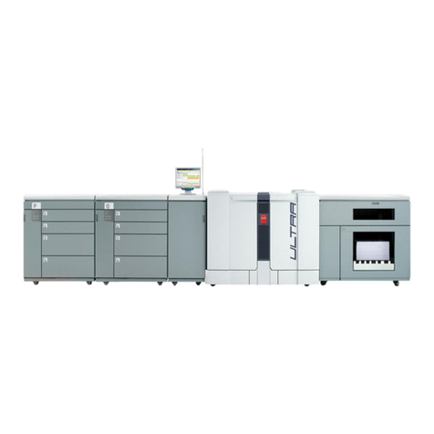
Océ
Océ VarioPrint®
6000 Ultra Line
Experience ultra
speed
User manual
Maintenance tasks

Copyright
© 2009 Océ
All rights reserved. No part of this work may be reproduced, copied, adapted, or transmitted
in any form or by any means without written permission from Océ.
Océ makes no representation or warranties with respect to the contents hereof and specifi-
cally disclaims any implied warranties of merchantability or fitness for any particular purpose.
Further, Océ reserves the right to revise this publication and to make changes from time
to time in the content hereof without obligation to notify any person of such revision or
changes.
Edition: 2009-08

Trademarks
List of trademarks
Océ, Océ VarioPrint® 6000 Ultra Line are registered trademarks of Océ-Technologies
B.V.
Products in this publication are referred to by their general trade names. In most, if not
all cases, these designations are claimed as trademarks or registered trademarks of their
respective companies.
3
Trademarks

Contents
Chapter 1
Introduction.........................................................................................................5
Notes for the reader...................................................................................6
Available documentation...........................................................................8
Introduction to the maintenance tasks.....................................................9
Determine the required maintenance.....................................................12
Chapter 2
Maintenance tasks - Level 1.............................................................................13
Replace the cleaners................................................................................14
Lock the clean unit (left)...........................................................................28
Lock the clean unit (right)........................................................................30
Chapter 3
Maintenance tasks - Level 2.............................................................................33
Remove sheets from the process modules............................................34
Clean the OPC belt (left)...........................................................................51
Clean the OPC belt (right)........................................................................56
Clean the glue cleaning rollers................................................................61
Appendix A
Miscellaneous....................................................................................................75
Reader's comment sheet.........................................................................76
Addresses of local Océ organisations ...................................................78
4
Contents

Chapter 1
Introduction

Notes for the reader
Introduction
This manual helps you to use the Océ VarioPrint® 6000 Ultra Line. The manual contains
a description of the product and guidelines to use and operate the Océ VarioPrint® 6000
Ultra Line.
Definition
Attention-Getters
Parts of this manual require your special attention. These parts can provide the following:
■Additional general information, for example, information that is useful when you
perform a task.
■Information to prevent personal injuries or property damage.
Warning, Caution and Note
The words Warning, Caution and Note draw your attention to important information.
Overview of the attention-getters#
IndicatesIconWord
Ignoring this warning could cause serious injury or
even death.
The Warning indication has several icons that warn
against various hazards. The icons are shown below.
Warning
General hazardWarning
Hot surfaceWarning
Electric shockWarning
Moving partsWarning
Chapter 1 - Introduction6
Notes for the reader

IndicatesIconWord
Laser beamWarning
Ignoring this warning could cause injury or damage to
property.
Caution
Indicates additional important information.Note
The use of heat-resistant gloves is mandatory when you
carry out these actions.
Safety information
Before using this Océ product, make sure that you read and understand the safety infor-
mation which is part of the user documentation. You can download the safety information
via http://global.oce.com/support/ or, if applicable, find it on the user documentation
CD/DVD that is delivered together with the machine or obtain the safety information
from your local Océ representative. To avoid potential hazards, maintenance is strictly
preserved to properly qualified and trained service technicians.
Chapter 1 - Introduction 7
Notes for the reader

Available documentation
Introduction
This machine is delivered with a documentation set that consists of the following items.
■A CD-ROM with all the manuals mentioned below
■Integrated Online Helps in the printer driver, the Settings Editor and other proprietary
applications.
Note:
Please check www.oce.com for the latest version of the documentation.
Main Content of the User Manuals
The following table provides an overview of the main content of the user manuals.
Main Content of the User Manuals#
Main contentUser Manual
■Overview of the main system components
■Working with the operator panel
■Handling and managing jobs on the operator panel
■Add media, toner and staples
Operating informa-
tion
■Replacing parts
■Cleaning parts
■Solve a paper jam in the engine module
Maintenance tasks
■Instructions for safe useSafety information
Chapter 1 - Introduction8
Available documentation

Introduction to the maintenance tasks
Introduction
This manual is intended for trained and certified operators who received the special
maintenance training for the printer. Therefore, this manual is only intended as a reference
guide for the described maintenance procedures.
On the operator panel, you must always press 'Next' to continue with the next step, or
'Finish' to complete a maintenance task. After you finished a maintenance task, the oper-
ator panel will also ask you to restart the system. The procedures in this manual only
describe the physical maintenance actions.
Note:
In this manual and on the operator panel, the trained and certified operator is referred
to as the key operator.
Note:
Only a key operator is allowed to perform the maintenance tasks that are described in
this manual. To make sure that only a key operator performs the maintenance tasks, it
is recommended to define a maintenance PIN in the Settings Editor. Then the operator
panel asks for the maintenance PIN when you start the first task of a maintenance session.
A maintenance session can involve more than 1 maintenance task. A maintenance session
ends when you leave the maintenance screen that displays the maintenance tasks. When
no maintenance PIN is defined in the Settings Editor, the operator panel will not ask
for a maintenance PIN.
The maintenance levels
The machine is a high-volume production printer. Therefore, a short downtime due to
required maintenance is very important to you. To help you reduce the downtime, 2
levels of maintenance tasks are defined which key operators can be allowed to do. The
following table gives an overview of the maintenance levels and the respective maintenance
tasks.
Chapter 1 - Introduction 9
Introduction to the maintenance tasks
Overview of the maintenance tasks#
Where to find more informa-
tion
Maintenance taskMaintenance level
‘Replace the cleaners’ on page 14Replace the cleaners1
■‘Lock the clean unit (left)’ on
page 28
■‘Lock the clean unit (right)’ on
page 30
Lock the clean units
‘Remove sheets from the process
modules’ on page 34
Solve paper jams in hot ar-
eas of the printer
2
■‘Clean the OPC belt (left)’ on
page 51)
■‘Clean the OPC belt (right)’
on page 56)
Clean the OPC belts
Begin maintenance
The maintenance section of the 'System' view shows the required or suggested maintenance
tasks. Here, you can only view the maintenance tasks.
[10] Begin maintenance
Chapter 1 - Introduction10
Introduction to the maintenance tasks
When you press the 'Start maintenance' button, the actual maintenance screen appears.
The maintenance screen
After you press the 'Start maintenance' button in the 'System' view, the maintenance
screen appears. The maintenance screen shows the required and suggested maintenance
tasks. A red icon indicates required tasks. A yellow icon indicates suggested tasks. These
tasks may be required soon. You can select a maintenance task from the list and press
'Start' to start the maintenance wizard.
Chapter 1 - Introduction 11
Introduction to the maintenance tasks

Determine the required maintenance
Introduction
The operator panel indicates that maintenance is required, and when maintenance is re-
quired. The operator panel also leads you through all the steps of each maintenance task.
This section describes how the operator panel indicates that the machine requires main-
tenance.
Replace the cleaners
The sheet cleaners and the spiral cleaners are consumables. The cleaners have counters.
If maintenance is required immediately or soon, the color of the maintenance icon changes.
The 'Maintenance' section of the 'System' view on the operator panel indicates that you
can or must replace the cleaners. There, the counter information is regularly updated.
The following table describes what you must do when the maintenance icon is blue, orange
or red.
When to replace the cleaners#
DescriptionMaintenance icon
The maintenance icon is blue. Maintenance is currently not
required.
The maintenance icon is orange. The machine can print another
20,000 images before you must replace the cleaners.
The maintenance icon is red. The counter is 0. The machine
stops. You must replace the cleaners. Only then, the machine
can continue printing.
Solve a paper jam in hot areas of the machine
When a paper jam occurs in the hot areas of the machine, the procedure is as follows.
■The machine stops.
■The operator panel displays the maintenance screen with this maintenance task.
■Select the maintenance task and press 'Start'.
■If applicable, enter the maintenance PIN.
■Follow the instructions on the operator panel to solve the paper jam.
Chapter 1 - Introduction12
Determine the required maintenance

Chapter 2
Maintenance tasks - Level
1

Replace the cleaners
Introduction
This procedure describes how to replace the charge unit.
When to do
If the maintenance icon in the dashboard indicates that maintenance is required soon or
immediately.
Before you begin
Make sure that you have 2 new spiral cleaners and 2 new sheet cleaners at hand.
Required tool
■D-wrench (supplied with the machine)
■Socket wrench 10 (supplied with the machine)
■Heat-resistant gloves (supplied with the machine)
■Adhesive tape (supplied with the machine)
Caution:
Certain parts of the machine may be hot. Therefore, always use the special heat- and oil-
resistant fuser gloves.
Open the doors and covers
1. Use socket wrench 10 to loosen the bolt of the front doors (1).
Chapter 2 - Maintenance tasks - Level 114
Replace the cleaners

2. Open the front doors (2).
1
2
[14] Open the front doors
3. Lift the right-hand top cover to the upper position (1).
4. Lift the left-hand top cover to the upper position (2).
21
[15] Lift the top covers
Caution:
Hot area. Use heat-resistant gloves.
Caution:
Make sure that the left-hand inner cover is locked in the upper position.
5. Unlock the left-hand upper cover and lift the left-hand inner cover to the upper position
(1).
Chapter 2 - Maintenance tasks - Level 1 15
Replace the cleaners

6. Unlock and lower the right-hand top cover (2).
2
1
[16] Lift the left-hand inner cover
Caution:
Make sure that the right-hand inner cover is locked in the upper position.
7. Lift the right-hand inner cover to the upper position.
[17] Lift the right-hand inner cover
Unlock the clean units
Caution:
Hot area. Use heat-resistant gloves.
1. Use the D-wrench to turn N1 counter-clockwise.
Chapter 2 - Maintenance tasks - Level 116
Replace the cleaners

2. Use the D-wrench to turn M1 counter-clockwise.
[18] Unlock the clean units
Lift the clean units
Caution:
Hot area. Use heat-resistant gloves.
Caution:
Make sure that both clean units are locked in the upper position.
1. Use the red handle to lift the right-hand clean unit to the upper position (1).
2. Use the red handle to lift the left-hand clean unit to the upper position (2).
12
[19] Lift the clean units
Chapter 2 - Maintenance tasks - Level 1 17
Replace the cleaners

Remove the sheet cleaners
Caution:
Hot area. Use heat-resistant gloves.
Attention:
Do not remove a layer of the sheet cleaner when the cleaner is inside the machine.
1. Press both red leaf springs at the end of the right-hand sheet cleaner outwards.
[20] Press the red leaf springs outwards
Chapter 2 - Maintenance tasks - Level 118
Replace the cleaners

2. Remove the sheet cleaner.
[21] Remove the sheet cleaners
3. Repeat the steps 1 and 2 for the left-hand sheet cleaner.
Remove the spiral cleaners
Caution:
Hot area. Use heat-resistant gloves.
Chapter 2 - Maintenance tasks - Level 1 19
Replace the cleaners

1. Press both red leaf springs at the end of the right-hand spiral cleaner outwards.
[22] Press the red leaf springs outwards
Chapter 2 - Maintenance tasks - Level 120
Replace the cleaners

Other manuals for VarioPrint 6000 Ultra Line
1
Table of contents
Other Oce All In One Printer manuals

Oce
Oce cm2510 Installation and operating manual

Oce
Oce VarioPrint 6000 MICR series User manual

Oce
Oce cm2520 User manual

Oce
Oce CM4520 User manual

Oce
Oce im4530 Configuration guide

Oce
Oce PP18C User manual

Oce
Oce VarioLink 5022 User manual

Oce
Oce im4511 Manual

Oce
Oce FX3000 SERIES User manual

Oce
Oce VarioLink 6022 User manual