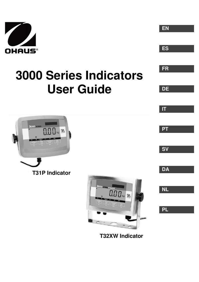
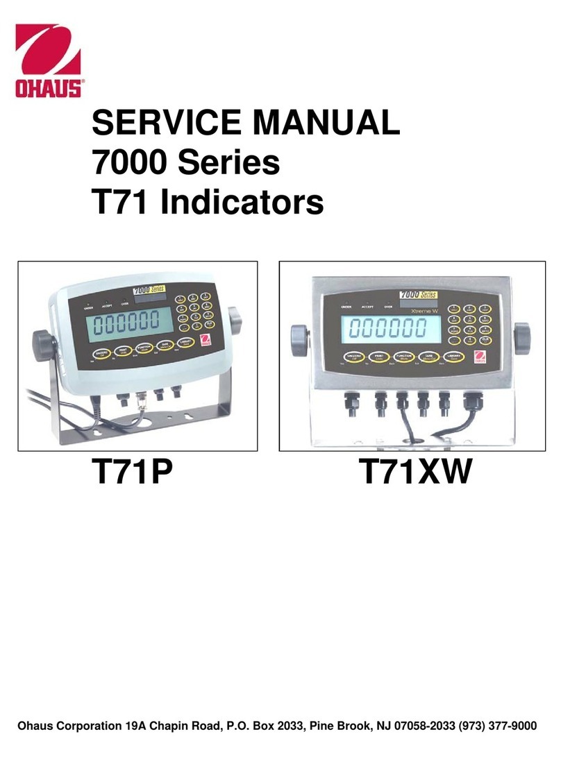
OHAUS CKW-55 User manual

Ohaus Corporation 19A Chapin Road, P.O. Box 2033, Pine Brook, NJ 07058 (973) 377-9000
CKW-55 INDICATOR
SERVICE MANUAL
T


The information contained in this manual is believed to be accurate at the time of publication,
but Ohaus Corporation assumes no liability arising from the use or misuse of this material.
Reproduction of this material is strictly prohibited.
Material in this manual is subject to change.
© Copyright 2006 Ohaus Corporation, all rights reserved.
® Registered trademark of Ohaus Corporation.
CKW-55 Indicator
CKW-55 Indicator
SERVICE MANUAL
T


i
TABLE OF CONTENTS
CHAPTER 1 INTRODUCTION
Page
1. Introduction ........................................................................................................ 1-1
1.1 Service Facilities .................................................................................................. 1-1
1.2 Tools and Equipment ........................................................................................... 1-2
1.2.1 Standard Tools and Test Equipment .......................................................... 1-2
1.2.2 Special Tools ......................................................................................... 1-2
1.3 Calibration Masses Required................................................................................. 1-2
1.4 Service Strategy ................................................................................................... 1-3
1.5 Safety and Environmental Protection ...................................................................... 1-3
CHAPTER 2 DIAGNOSIS
2. Diagnosis .......................................................................................................... 2-1
2.1 Basic Examination .............................................................................................. 2-1
2.2 Preliminary Checks .............................................................................................. 2-1
2.3 Troubleshooting Tables ........................................................................................ 2-1
2.4 Error Code Table .................................................................................................. 2-6
CHAPTER 3 CKW-55 INDICATOR TESTING
3. Indicator Testing.................................................................................................. 3-1
3.1 Membrane Switch Testing ..................................................................................... 3-1
3.2 Main PC Board Testing......................................................................................... 3-3
3.2.1 Voltage Measurements ............................................................................ 3-3
3.2.2 Simulator Testing .................................................................................... 3-6
3.3 Power Supply Testing ........................................................................................... 3-7
3.3.1 Voltage measurements ............................................................................ 3-7
3.4 Battery Testing .................................................................................................... 3-8
3.4.1 General Information ................................................................................ 3-8
3.4.2 Troubleshooting the Battery ...................................................................... 3-9
3.5 Recharge Board Testing ..................................................................................... 3-10
3.5.1 Recharge Board Information................................................................... 3-10
3.5.2 Recharge Board Testing......................................................................... 3-11
3.5.3 Voltage Measurements .......................................................................... 3-12
3.6 Relay Board Testing ........................................................................................... 3-13
3.6.1 Relay Kit Information ............................................................................. 3-13
3.6.2 Relay Testing........................................................................................ 3-13
3.7 RS322, RS422/485 Communication Testing ........................................................ 3-16
3.7.1 RS422/485 Communication Board Information ........................................ 3-16
3.7.2 RS232 Testing...................................................................................... 3-16
3.7.3 RS422/485 Testing............................................................................... 3-18
3.8 External Input Testing ......................................................................................... 3-20
3.9 Operational Testing ............................................................................................ 3-21
3.9.1 Indicator Display Segment Test- Power On Sequence ................................ 3-21
3.9.2 Turning Off the Indicator ......................................................................... 3-22
3.9.3 Performance Testing ............................................................................. 3-22
3.9.4 Checking Menu Library Settings .............................................................. 3-23
ii
TABLE OF CONTENTS (Cont.)
CHAPTER 3 CKW-55 INDICATOR TESTING (Cont.)
3.10 Specifications .................................................................................................... 3-25
3.11 Calibration using an External Base ...................................................................... 3-26
3.12 Calibration3-28
3.12.1 Span Calibration ................................................................................... 3-27
3.12.2 Linearity Calibration............................................................................... 3-28
3.14.3 Calibration Test ..................................................................................... 3-29
3.13 Geographical Adjustment Factor .......................................................................... 3-30
3.14 Calibration Verification using Load Cell Simulator ................................................... 3-32
3.14.1 Calibration Test Using a Simulator........................................................... 3-33
CHAPTER 4 REPAIR PROCEDURES
4. Repair Procedures................................................................................................ 4-1
4.1 Opening the Indicator Housing .............................................................................. 4-1
4.2 Replacing the Membrane Switch ............................................................................ 4-1
4.3 Replacing the Main PC Board ............................................................................... 4-2
4.4 Replacing the Power supply .................................................................................. 4-2
4.5 Replacing the Optional Recharge Board .................................................................. 4-3
4.6 Replacing the Optional Relay Board ....................................................................... 4-3
4.6.1 Relay Board Replacement Procedure ......................................................... 4-3
4.6.2 Relay Replacement ................................................................................. 4-4
4.7 Replacing the Optional RS422/485 Communication Board ...................................... 4-4
4.8 Replacing the Optional Rechargeable Battery .......................................................... 4-5
4.9 Replacing the Real-Time Clock (RTC) Battery .......................................................... 4-6
CHAPTER 5 PARTS LISTS
5. Parts Lists .......................................................................................................... 5-1
5.1 CKW-55 Indicator Exploded View .......................................................................... 5-2
5.2 CKW-55 Indicator Parts List.................................................................................. 5-3
5.3 CKW-55 Column Exploded View ........................................................................... 5-4
APPENDIX A SERVICE MODE ........................................................................................ A-1
A.1 Service Mode ...................................................................................................... A-1
A.1.1 Service Mode Commands ........................................................................ A-1

iii
TABLE NO. TITLE PAGE
1-1 Calibration Masses .............................................................................................. 1-2
2-1 Indicator Will Not Turn On With AC Power ............................................................... 2-1
2-2 Indicator Will Not Turn On Using Battery Power (Optional) ........................................ 2-2
2-3 Indicator Does Not Respond To Front Panel Controls ............................................... 2-3
2-4 No LED or Bar Display or Partial Display ................................................................ 2-3
2-5 RS232 Communication Failure.............................................................................. 2-4
2-6 RS422/485 Communication Failure (Optional Board) .............................................. 2-4
2-7 Relay Operation Failure (Optional board)................................................................ 2-4
2-8 Indicator Display Incorrect or Unstable ................................................................... 2-5
2-9 Unable to Maintain Time and Date Functions........................................................... 2-5
2-10 Error Code Table ................................................................................................. 2-6
3-1 Membrane Switch Continuity Test .......................................................................... 3-2
3-2 Serial Interface Commands Table ........................................................................ 3-17
3-3 External Input Selections ..................................................................................... 3-20
3-4 Specifications .................................................................................................... 3-25
3-5 Geographical Adjustment Values ......................................................................... 3-31
3-6 Load Cell Output Readings for CKW Bases ........................................................... 3-34
5-1 CKW-55 Indicator Parts List .................................................................................. 5-3
5-2 CKW-55 Column Parts List ................................................................................... 5-4
A-1 Service Mode Commands ..................................................................................... A-1
A-2 ASCII Number to Character Conversion ................................................................... A-2
LIST OF TABLES

iv
FIGURE NO. TITLE PAGE
3-1 Scale Membrane Switch Wiring Diagram ................................................................ 3-2
3-2 Interconnection Diagram ...................................................................................... 3-4
3-3 Component Layout Diagram ................................................................................. 3-5
3-4 Power Supply Location Diagram ........................................................................... 3-7
3-5 Battery Charging Indications ................................................................................. 3-8
3-6 Battery and Recharge Board location Diagram ........................................................ 3-9
3-7 Relay Board With Terminal Cover ........................................................................ 3-14
3-8 Relay Board Without Terminal Cover .................................................................... 3-14
3-9 RS422/485 Typical 4-wire Duplex Connection ...................................................... 3-18
3-10 RS422/485 Typical 2-Wire Half Duplex Connection ............................................... 3-18
3-11 RS422/485 Location in Housing ......................................................................... 3-19
3-12 Main Printed Circuit Board .................................................................................. 3-26
3-13 Open and Shorted Jumpers ................................................................................ 3-28
3-14 Main Printed Circuit Board Connections ................................................................ 3-32
3-15 Open and Shorted Jumpers ................................................................................ 3-32
4-1 RTC Battery Removal/Installation ........................................................................... 4-6
5-1 Exploded View of CKW-55 Indicator....................................................................... 5-2
5-2 Exploded View of CKW Column ............................................................................. 5-4
LIST OF ILLUSTRATIONS

1-1
CHAPTER 1 INTRODUCTION
1. INTRODUCTION
This service manual contains instructions for the diagnosis and repair work to be performed by qualified
Ohaus service technicians or Ohaus authorized service centers. Knowledge of the operation of the CKW-
55 Indicator is assumed. Instruction manuals may be required with this service manual. For complete
information on operation, refer to the CKW-55 Indicator and CKW Series Scale Instruction Manual.
This manual covers troubleshooting, repair and testing of the CKW-55 Indicator.
The contents of this manual are contained in five chapters and an Appendix with service menu instructions.
Chapter 1 Introduction - Contains information about service facilities, tools, test equipment, test
masses, and service strategy.
Chapter 2 Diagnosis - Contains information on problem verification, indicator examination, preliminary
checks, troubleshooting tables, interconnection diagrams and wiring diagrams.
Chapter 3 CKW-55 Indicator Testing and Calibration - Contains testing procedures, performance tests,
specifications and calibration of the CKW-55 Indicator.
Chapter 4 Repair Procedures - Contains detailed repair procedures for all major assemblies of the CKW-
55 Indicator including the optional Relay Board, RS422/485 Communication Board, the Recharge Board
and Battery.
Chapter 5 Parts Lists - Contains an exploded view identifying all serviceable replacement assemblies
with associated parts lists.
Appendix A CKW-55 Indicator Service Menu - Contains RS232 commands for the CKW-55 Indicator
in a service mode.
1.1 SERVICE FACILITIES
The service area should be a stable environment.
The bench area should be clean and should contain an antistatic mat with a personnel-grounding clip
to protect internal circuit boards. The ideal electrical power source for the indicator should be a dedicated
line to avoid sudden fluctuations or voltage drops caused by external equipment drawing heavy current.
The service area for the indicator should be away from direct sunlight, overhead heating or air conditioning
ducts, magnetic fields such as motors or large transformers or near vibrating sources such as machinery,
motors or vibrating equipment.
The power outlet should be grounded for safety. Sufficient space should be provided around the indicator
as not to be affected by other equipment. This will ensure that the indicator is operated under ideal
conditions.

1-2
CHAPTER 1 INTRODUCTION
1.2 TOOLS AND EQUIPMENT
1.2.1 Standard Tools and Test Equipment
The service shop should contain the following equipment:
1. Digital Voltmeter (DVM).
2. Megohmeter
3. Standard Electronics tool kit.
4. Desk magnifier on a stand.
5. Grounding mat and clip.
6. Flat blades and holder.
1.2.2 Special Tools
To service the CKW-55 Indicator, the following equipment is recommended:
1. A Load Cell Simulator
2. A computer
3. RS232 Cable Printer SF42 PN 80500574
4. RS232 Cable/PC 25-pin PN 80500553
5. RS232 Cable/PC 9-pin PN 80500552
1.3 CALIBRATION MASSES REQUIRED
The calibration masses required is dependent on the capacity and readability of the base used. The masses
required to test the CKW-55 Indicator when connected to an Ohaus CKW base must meet the requirements
of ASTM Class 4 or OIML F2. The mass values are listed in Table 1-1.
TABLE 1-1. CALIBRATION MASSES
MODEL Span Cal Linearity Cal
Cal in kg: Masses Totaling Masses Totaling
CKW3R55 3kg 1kg & 3kg
CKW6R55 6kg 3kg & 6kg
CKW15L55 15kg 7kg & 15kg
CKW30L55 30kg 15kg & 30kg
NOTE: During span calibration, a new span value may be entered. The span allowable range is 1kg or
1lb to 100% full scale. During linearity calibration a new midpoint value may be entered, the allowable
range is 25% to 75% full-scale capacity (whole numbers only). Values closest to 1/2 span capacity
will result in more accurate linearity.

1-3
CHAPTER 1 INTRODUCTION
1.4 SERVICE STRATEGY
The repair method for the CKW-55 Indicator is the direct replacement of major assemblies.
The CKW-55 Indicator contains the following replaceable assemblies: Cover Assembly with Membrane
Switch, Main PC Board with LED and Bar Displays, and Power Supply PCB. Optional assemblies consist
of: NiMH Rechargeable Battery, Battery Recharge PCB, RS422/485 Communication PCB, and an AC or
DC Relay Board.
This service manual contains sufficient information to isolate the problem, replace the assembly, test and
restore the Indicator to original factory specifications.
1.5 SAFETY AND ENVIRONMENTAL PROTECTION
When carrying out service or repair work, always observe the following.
• Before opening the Indicator, isolate it from the AC power line (pull out the
plug).
• The Indicator contains sensitive electronic components that are sensitive to
electrostatic discharge. We recommend that you wear a grounding wrist
strap when doing any work in the interior of the Indicator, in order to prevent
any electrostatic charge building up. Grounding wrist straps are commercially
available from electronic component suppliers. Use only ground straps that
include a protective series resistor in the assembly.
• Indicators have a built-in memory backup battery and may contain an optional
rechargeable battery. These contain heavy metals which could be hazardous
to the environment. Batteries must not be disposed of as normal domestic
refuse. Please ensure that used, non-working batteries are disposed of
correctly in accordance with the relevant local regulations.
• When this symbol is displayed, important information regarding mainte-
nance instructions should be carefully read before proceeding.

1-4
CHAPTER 1 INTRODUCTION

2-1
CHAPTER 2 DIAGNOSIS
SYMPTOM
Indicator will not turn on with
AC Power supply connected.
PROBABLE CAUSE
Power cord defective.
REMEDY
Check the power cord for cuts or abra-
sions. If OK, proceed.
Refer to section 4.1 and open the indi-
cator.
CAUTION:
Hazardous voltages are present; use
extreme care when making measure-
ments.
Check ac voltage at the Power
Supply Board, on connector CN1. Move
the power cord and see If the ac line
voltage remains constant on the con-
nector. If not, replace the power cord. If
OK, proceed.
2. DIAGNOSIS
This section contains information needed to properly evaluate the reported problem and diagnose its
cause.
2.1 BASIC EXAMINATION
Set up the Indicator according to the Instruction manual. Allow the Indicator to stabilize to room
temperature. Examine the Indicator for signs of corrosion or physical damage.
2.2 PRELIMINARY CHECKS
Connect the Indicator’s power cord to a suitable AC power source. Turn the Indicator on. Refer to Section
3.9.1 and observe and record power on information codes and software revision. Record all menu
settings if possible as received. See section 3.9.4. On indicators equipped with an optional battery, allow
the battery to charge up completely at least 4 hours with the indicator turned off. The front panel bar LED’s
will indicate a full charge when the first green segment begins to blink. If the battery fails to charge, “Lo-
Bat” may display when the Indicator is turned on. If a battery problem exists, refer to section 3.7 for
corrective actions and testing.
NOTENOTE
NOTENOTE
NOTE: This manual covers only Indicator problems. Some testing requires the Indicator to be connected
to a known good base. For base problems, refer to the Base Service Manual. If the Indicator is not supplied
with a base, testing will be done using a known good base and or Loadcell Simulator.
2.3 TROUBLESHOOTING TABLES
Troubleshooting tables 2-1 through 2-10 identify problems that could be encountered with the Indicator.
The troubleshooting tables refer to interconnection and wiring diagrams in this section to assist in locating
the problem.
2-1 INDICATOR WILL NOT TURN ON WITH AC POWER.

2-2
CHAPTER 2 DIAGNOSIS
SYMPTOM
Indicator will not turn on with
AC Power supply connected
(Cont.).
PROBABLE CAUSE
Power Supply defective.
Membrane Switch defective.
Main PC Board is defective.
REMEDY
Refer to section 3.3 and test the Power
Supply. Replace if necessary. See Re-
pair Procedure 4.4. If Power supply is
OK, proceed.
Refer to section 3.1 and test the Mem-
brane Switch. Replace if necessary. See
Repair Procedure 4.2. If Membrane
Switch is OK, proceed.
The Main PC Board should be tested in
accordance with section 3.2. The Main
PC Board if defective should be replaced.
See Repair Procedures 4.3. After repair,
perform Operational Tests in section 3.9.
2-1 INDICATOR WILL NOT TURN ON WITH AC POWER (Cont.)
SYMPTOM
Indicator will not turn on using
battery power.
PROBABLE CAUSE
Battery discharged or defec-
tive.
Wiring harness defective or
battery connection broken.
Recharge Board defective.
Membrane Switch defective.
REMEDY
Refer to section 3.7 and test the battery.
Replace if necessary. See Repair Proce-
dure 4.8.
Refer to section 4.1 and open the scale.
Refer to section 3.7 and test the battery
harness. If OK, proceed.
Refer to section 3.5 and test the Re-
charge Board. Replace if necessary.
See Repair Procedure 4.5. If Recharge
Board is OK, proceed.
Refer to section 3.1 and test the Mem-
brane Switch. Replace if necessary. See
Repair Procedure 4.2
TABLE 2-2 INDICATOR WILL NOT TURN ON USING BATTERY POWER (OPTIONAL).

2-3
CHAPTER 2 DIAGNOSIS
SYMPTOM
Indicator will not turn on using
battery power (Cont.).
PROBABLE CAUSE
Main PC Board is defective.
REMEDY
The Main PC Board should be tested in
accordance with section 3.2. The Main
PC Board if defective should be replaced.
See Repair Procedures 4.3. After repair,
perform Operational Tests in section 3.9.
TABLE 2-2 INDICATOR WILL NOT TURN ON USING BATTERY POWER (OPTIONAL)(Cont.).
SYMPTOM
Indicator does not respond to
front panel controls.
PROBABLE CAUSE
Membrane Switch is defec-
tive.
Main PC Board defective
Locked out key function.
REMEDY
Refer to section 3.1 and test the Mem-
brane switch. Replace if necessary. See
Repair Procedure 4.2.
If membrane switches are OK, refer to
section 3.2 and test the Main PC Board.
If defective, replace the Main PC Board.
See Repair Procedures 4.3. After repair,
perform Operational Tests in section
3.9.
Review lockout menu in user manual.
TABLE 2-3 INDICATOR DOES NOT RESPOND TO FRONT PANEL CONTROLS.
SYMPTOM
Display is not on or partial
characters are displayed.
PROBABLE CAUSE
Main PC Board is defective
or LED may be defective.
REMEDY
The Main PC Board is replaced as a
whole assembly. Check procedures in
Table 2-1 first and verify that other prob-
lems do not exist. Then, refer to section
3.2 and test the Main PC Board.
Replace Main PC Board. See Repair
Procedures 4.3. After repair, perform
Operational Tests in section 3.9.
TABLE 2-4 NO LED OR BAR DISPLAY OR PARTIAL DISPLAY.

2-4
CHAPTER 2 DIAGNOSIS
SYMPTOM
Cannot communicate using
optional RS422/485 board.
NOTE: The RS232 must be op-
erational or the RS422/485 will
not function.
PROBABLE CAUSE
Menu settings improperly set.
Loose wiring connections.
RS422/485 PC board defec-
tive.
Main PC board defective.
REMEDY
Refer to the Instruction Manual and
check the menu settings. If OK, pro-
ceed.
Refer to Figure 3-2 for proper cable
connections.
Refer to section 3.7 and test the RS422/
485 board. If defective replace, see
section 4.7. After repair, perform Op-
erational Tests in section 3.9.
The Main PC Board should be tested in
accordance with section 3.2. The Main
PC Board if defective should be re-
placed. See Repair Procedures 4.3.
After repair, perform Operational Tests
in section 3.9.
TABLE 2-6 RS422/485 COMMUNICATIONS FAILURE (OPTIONAL BOARD).
SYMPTOM
Cannot communicate using
RS232.
PROBABLE CAUSE
Menusettings improperly set.
Main PC board defective.
REMEDY
Refer to the Instruction Manual and
check the menu settings. Test the
RS232 communications, see section
3.7.2.
If communications cannot be estab-
lished, the Main PC Board should be
tested in accordance with section 3.2.
The Main PC Board if defective should
be replaced. See Repair Procedures
4.3. After repair, perform Operational
Tests in section 3.9.
TABLE 2-5 RS232 COMMUNICATIONS FAILURE.
TABLE 2-7 RELAY OPERATION FAILURE (OPTIONAL BOARD).
SYMPTOM
Relay functions not working.
PROBABLE CAUSE
Menusettings improperly set.
Relay Board defective.
REMEDY
Refer to the Instruction Manual and
check the menu settings.
Refer to section 3.6 and test the Relay
board. If OK, proceed. If defective
replace, see section 4.6. After repair,
perform Operational Tests in section
3.9.

2-5
CHAPTER 2 DIAGNOSIS
SYMPTOM
Incorrect.
Unstable.
PROBABLE CAUSE
Menusettings improperly set.
Loose or improper wiring.
Improper calibration.
Check base used with the
indicator.
Main PC Board defective.
TABLE 2-8 INDICATOR DISPLAY INCORRECT OR UNSTABLE.
REMEDY
Refer to instruction manual and check
the menu settings. Perform Opera-
tional Tests in section 3.9.
Check wiring on connector J2.
Recalibrate properly. See section 3.11.
Examine the base and check settings
on the indicator or test using load cell
simulator.
The Main PC Board should be tested in
accordance with section 3.2. The Main
PC Board if defective should be re-
placed. See Repair Procedures 4.3.
After repair, perform Operational Tests
in section 3.9.
SYMPTOM
Fails to maintain set time and
date.
PROBABLE CAUSE
Real Time Clock (RTC) bat-
tery depleted.
Main PC Board defective.
TABLE 2-9 UNABLE TO MAINTAIN TIME AND DATE FUNCTIONS.
REMEDY
Replace the Real Time Clock battery.
Refer to section 4.9. After repair, reset
the time and date in accordance with
user's local area. If time and date
cannot be set with a new battery, pro-
ceed.
The Main PC Board should be tested in
accordance with section 3.2. The Main
PC Board if defective should be re-
placed. See Repair Procedures 4.3.
After repair, perform Operational Tests
in section 3.9.
TABLE 2-7 RELAY OPERATION FAILURE (OPTIONAL BOARD) (Cont.).
SYMPTOM
Relay functions not working
(Cont.).
PROBABLE CAUSE
Main PC Board defective.
Loose or improper wire con-
nections.
REMEDY
The Main PC Board should be tested in
accordance with section 3.2. The Main
PC Board if defective should be re-
placed. See Repair Procedures 4.3.
After repair, perform Operational Tests
in section 3.9.
Refer to Figure 3-2 for proper wiring.

2-6
CHAPTER 2 DIAGNOSIS
SYMPTOM
Err 1
Err 2
Err 3 (LFT mode only)
Err 7
Err 10
Err 14
Err 21
PROBABLE CAUSE
Overload condition, the load
on the Platform exceeds the
rated capacity of the base
used with the Indicator
Underload condition.
Poweron zero exceeds +10%
of original calibration zero.
EEPROM data incorrect on
Main PC board.
Library or Real Time Clock
(RTC) data incorrect.
Zero value exceeds the % zero
setting value.
Calibration incorrect.
REMEDY
Remove excess load. Turn Indicator off
then on. Perform calibration. Refer to
section 3.11 when using a base or
section 3.14 when using a simulator.
Replace platform if removed, cycle power
off then on, see section 3.11 or 3.14 and
calibrate the Indicator.
Clear platform of excess mass, or
recalibrate to establish a new zero point.
Go through all menus and re-establish
all settings or go to each menu and reset
to default settings. Check operation of
Indicator , see section 3.9. If this fails,
the Main PC board is defective. Refer to
section 4.3 and replace the Main PC
board. Check operation of Indicator , see
section 3.9.
Replace RTC (Lithium) back-up battery.
Refer to section 4.9 and replace the
battery.
Remove excess load from the base or
platform. Select a higher Zero Range
value,(Non-LFT only.) in the Setupmenu.
Performcalibration using propermasses.
Perform Operational Tests, see section
3.8.
2.4 ERROR CODE TABLE
The CKW-55 Indicator is equipped with software which will display an error code under certain conditions.
Review the listed codes and follow instructions to correct the problem.
TABLE 2-10. ERROR CODES

2-7
CHAPTER 2 DIAGNOSIS
SYMPTOM
Lo bAt
CLr.Pan
PROBABLE CAUSE
Battery is discharged.
Battery is defective.
Power on zero exceeds
+10% of original calibra-
tion zero.
REMEDY
Connect Indicator to AC power and al-
low battery to charge.
Refer to section 3.4 and test the battery.
Replace if necessary. See Repair Proce-
dure 4.8.
Clear platform of excess masses, or
recalibrate to establish a new zero point.
Refer to section 3.11.
NoteNote
NoteNote
Note: After several seconds, NON-LFT
units will accept the new zero point. LFT
enabled units will change to Err 3 if
condition is not corrected.
TABLE 2-10. ERROR CODES (Cont.)

2-8
CHAPTER 2 DIAGNOSIS
Other manuals for CKW-55
2
Table of contents
Other OHAUS Touch Panel manuals

OHAUS
OHAUS 3000 Series T31P User manual

OHAUS
OHAUS T32ME User manual

OHAUS
OHAUS CD-31 User manual

OHAUS
OHAUS T71P User manual

OHAUS
OHAUS T51P User manual

OHAUS
OHAUS T51P User manual

OHAUS
OHAUS 5000 Series User manual

OHAUS
OHAUS 3000 Series T32XW User manual

OHAUS
OHAUS T71P User manual

OHAUS
OHAUS TD52 User manual
Popular Touch Panel manuals by other brands

Avalue Technology
Avalue Technology FPC 17 W Series Quick reference guide

panel
panel PSG201-FM Series user manual

Scaime
Scaime eNodTouch-M instruction manual

Pixsys
Pixsys TD Series quick start guide

AMX
AMX Modero ViewPoint MVP-8400 Operation/reference guide

ICOP Technology
ICOP Technology PPC-150P-EHL Series user manual