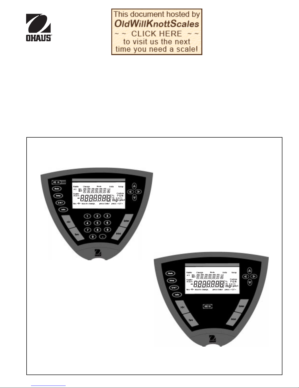
OHAUS CD-31 User manual

1
CD Indicators
INSTRUCTION MANUAL
Models CD-31 and CD-33 Indicators
Ohaus CorporationOhaus Corporation
Ohaus Corporation
29 Hanove
r
Road
Flo
r
ha
m
Pa
r
k,NJ
07932-0900

2
CD Indicators
IEC1010-1 & EN60950:1992 Safety Regulations
IEC1010-1 & EN60950:1992 Sicherheitsbestimmungen
IEC1010-1 & EN60950:1992 Consignes de sécurité
IEC1010-1 & EN60950:1992 Disposiciones sobre seguridad
IEC1010-1 & EN60950:1992 Prescrizioni . di sicurezza
EN55022:1987 Emissions
EN50082-1:1992 Immunity
NOTE: The displayed value may be adversely affected under
extreme electromagnetic influences, eg. when using a radio unit in the
immediate vicinity of the device. Once the interference has been
rectified, the product can once again be used for its intended purpose.
EN55022:1987 Funkstörungen
EN50082-1:1992 Immunität
Hinweis: Unter extremen elektromagnetischen Einflüssen z.B. bei
Betreiben eines Funkgerätes in unmittelbarer Nähe des Gerätes kann
eine Beeinflussung des Anzeigewertes verusacht werden. Nach Ende
des Störeinflusses ist das Produkt wieder bestimmungsgemäss
benutzbar.
EN55022:Emissions parasites
EN50082-1:1992 Immunité
Remarque: Dans des conditions d'influences électromagnètiques
extrêmes, par exemple en cas d'exploitation d'un appareil radio à
proximité immédiate de l'appareil la valeur d'affichage risque d'être
influencée. Une fois que l'influence parasite est terminée, le produit
peut être de nouveau utilisé de manière conforme aux prescriptions.
EN55022:1987 Radiointerferencias
EN50082-1:1992 Inmunidad
Nota: Bajo influencias electromagnèticas extremas, p.ej. cuando
funciona una radio en las inmediaciones del aparato, se pueden
alterar los valores del display. Cuando concluye el efecto perturbador,
el producto puede ser utilizado de nuevo, de acuerdo con lo
estipulado.
EN55022:1987 Radiointerferenze
EN50082-1:1992 Immunità
Nota: ll valore visualizzato può essere influenzato negativamente dalla
presenza di forti interferenze elettromagnetiche, per esempio quando
viene usata una radio in prossimità della bilancia. Eliminata la fonte
dell'interferenza, il prodotto può essere nuovamente utilizzato per le
funzioni cui è preposto.
EU 73/23 Low Voltage
EU 73/23 Niederspannung
EU 73/23 Basse tension
EU 73/23 Baja tensión
EU 73/23 Bassa tensione
EU 89/336, 92/31, 93/68
Electromagnetic compatibility
EU 89/336, 92/31, 93/68
Elektromagnetische Verträglichkeit
EU 89/336, 92/31, 93/68
Compatibilité électromagnétique
EU 89/336, 92/31, 93/68
Compatibilidad electromagnética
EU 89/336, 92/31, 93/68
Compatibilità elettromagnetica
Ohaus Corporation, 29 Hanover Road, Florham Park, New Jersey, 07932, USA
Declaration of Conformity We, Ohaus Corporation, declare under our sole responsibility that the instrument models listed below marked with
“CE” - are in conformity with the directives and standards mentioned.
Konformitätserkärung Wir, die Ohaus Corporation, erklären in alleiniger Verantwortung, dass die untenstehenden Waagentypen, instrument
mit “CE” - mit den genannten Richtlinien und Normen übereinstimmen.
Déclaration de conformité Nous, Ohaus Corporation, déclarons sous notre seule responsabilité, que les types de instrument ci-dessous cité
- munis de la mention «CE» - sont conformes aux directives et aux normes mentionnées ci-après.
Declaración de Conformidad Nostras, Ohaus Corporation, declaramos bajo responsabilidad exclusiva que los modelos de instrumento
indicados a continuación - con el distintivo ,CE’ - están conformes con las directivas y normas citadas.
Dichiarazione di conformità Noi, Ohaus Corporation, U.S.A, dichiariamo sotto nostra unica responsabilità, che i tipi di strumento specificati di
seguito - contrassegnati con la marcatura “CE” - sono conformi alle direttive e norme citate.
Instrument Type/Waagentyp/Type de instrument/Modelo de instrumento/Tipo di strumento CD-31/CD-33 Indicators
Marked with: Directive Standard
Gekennzeichnet mit: Richtlinie Norm
Munis de la mention: Directive Norme
Con el distintivo: Directiva Norma
Contrassegnati con la Direttiva Norma
Marcatura:

3
CD Indicators
NOTE: THIS EQUIPMENT HAS BEEN TESTED AND FOUND TO COMPLY WITH THE LIMITS FOR A CLASS A DIGITAL
DEVICE, PURSUANT TO PART 15 OF THE FCC RULES.
THESE LIMITS ARE DESIGNED TO PROVIDE REASONABLE PROTECTION AGAINST HARMFUL INTERFERENCE
WHEN THE EQUIPMENT IS OPERATED IN A COMMERCIAL ENVIRONMENT. THIS EQUIPMENT GENERATES,
USES, AND CAN RADIATE RADIO FREQUENCY ENERGY AND, IF NOT INSTALLED AND USED IN ACCORDANCE
WITH THE INSTRUCTION MANUAL, MAY CAUSE HARMFUL INTERFERENCE TO RADIO COMMUNICATIONS. OP-
ERATION OF THIS EQUIPMENT IN A RESIDENTIAL AREA IS LIKELY TO CAUSE HARMFUL INTERFERENCE IN
WHICH CASE THE USER WILL BE REQUIRED TO CORRECT THE INTERFERENCE AT HIS OWN EXPENSE.
THIS DIGITAL APPARATUS DOES NOT EXCEED THE CLASS A LIMITS FOR RADIO NOISE EMISSIONS FROM
DIGITAL APPARATUS AS SET OUT IN THE INTERFERENCE-CAUSING EQUIPMENT STANDARD ENTITLED “DIGI-
TAL APPARATUS”, ICES-003 OF THE DEPARTMENT OF COMMUNICATIONS.
CET APPAREIL NUMERIQUE RESPECTE LES LIMITES DE BRUITS RADIOELECTRIQUES APPLICABLES AUX
APPAREILS NUMERIQUES DE CLASSE A PRESCRITES DANS LA NORME SUR LE MATERIEL BROUILLEUR :
“APPAREILS NUMERIQUES”, NMB-003 EDICTEE PAR LE MINISTRE DES COMMUNICATIONS.
Unauthorized changes or modifications to this equipment are not permitted.
Before plugging in the Indicator, make sure that the
voltage of the power adapter and plug match.

4
CD Indicators
TABLE OF CONTENTS
OVERVIEW OF CONTROLS ........................................................................................................................ 1
OVERVIEW OF DISPLAY INDICATORS ...................................................................................................... 2
1. GETTING TO KNOW YOUR INDICATOR ............................................................................................................ 3
1.1 Introduction3
2. INSTALLATION ................................................................................................................................................... 3
2.1 Unpacking and Checking .................................................................................................................................... 3
2.2 Selecting the Location ........................................................................................................................................ 3
2.3 Connecting the Indicator to a Scale base ........................................................................................................... 4
2.4 Connecting the RS232 Interface ......................................................................................................................... 4
2.4.1 Hardware .................................................................................................................................................. 4
2.5 Connecting Power ............................................................................................................................................... 5
2.5.1 Cautionary Notes ...................................................................................................................................... 5
2.5.2 Turning On the Indicator ............................................................................................................................ 5
2.5.3 Power ON/OFF ......................................................................................................................................... 5
2.6 Scale Base Setup ............................................................................................................................................... 6
3. SETTING UPYOUR INDICATOR ...................................................................................................................... 10
3.1 Setting Time and Date ...................................................................................................................................... 10
3.2 Readout ..................................................................................................................................................... 11
3.3 Good Manufacturing Practices (GMP) Data ...................................................................................................... 13
3.4 Good Manufacturing Practices (GMP) Set ........................................................................................................ 14
3.5 Print ..................................................................................................................................................... 15
3.6 RS232 ..................................................................................................................................................... 16
3.7 Legal for Trade (LFT) ......................................................................................................................................... 17
3.8 Mode ..................................................................................................................................................... 18
3.9 Units ..................................................................................................................................................... 19
3.10 Global ..................................................................................................................................................... 19
3.11 Custom Unit ............................................................................................................................................... 21
3.12 Menu Lock-Out Protection .......................................................................................................................... 22

5
CD Indicators
TABLE OF CONTENTS (Cont.)
4. OPERATINGYOUR INDICATOR ....................................................................................................................... 23
4.1 Calibration23
4.1.1 Span Calibration ..................................................................................................................................... 24
4.1.2 User Calibration ...................................................................................................................................... 25
4.1.3 Linearity Calibration ................................................................................................................................ 26
4.1.4 Calibration Test ....................................................................................................................................... 37
4.1.5 Calibration GMP Printout ........................................................................................................................ 28
4.2 Weighing 29
4.2.1 Manual Taring .......................................................................................................................................... 29
4.2.2 Preset Taring ........................................................................................................................................... 30
4.3 Percent Weighing .............................................................................................................................................. 31
4.4 Parts Counting .................................................................................................................................................. 32
4.5 Animal Weighing ............................................................................................................................................... 33
4.6 Checkweigh34
4.7 Printing Data............................................................................................................................................... 35
4.7.1 RS232 Commands .................................................................................................................................. 35
4.7.2 Output Formats....................................................................................................................................... 35
5. CARE AND MAINTENANCE ............................................................................................................................ 38
5.1 Troubleshooting ................................................................................................................................................. 38
5.2 Error Codes List ................................................................................................................................................ 39
5.3 Service Information ........................................................................................................................................... 40
5.4 Replacement Parts ........................................................................................................................................... 40
5.5 Accessories40
5.6 Technical Data .................................................................................................................................................. 40

6
CD Indicators
OVERVIEW OF CONTROLS
3
4
2
5
6
8
9
10
7
11
No. Designation Function
1Mode button Selects standard weighing, percent, parts counting, check weighing and animal weighing.
2Setup button Selects various submenus: scale, calibration, date, time, readout, GMP data, GMP set,
print, RS232, LFT, mode, units, global, custom.
3 G/N/T button Selects Gross, Net or Tare weights.
4 Units button Selects weighing units: grams, kilograms, pounds, custom, parts counting, percent.
5>0< button When pressed, zero's scale.
6 Tare button When pressed, performs tare function.
7 Numeric keypad 0 to 9 keys and decimal point keypad, used to enter numerical data on Model CD-33.
8Display LCD display indicates weight, modes and setup information.
9 Arrow buttons when pressed, travels up through submenus. button when pressed, travels
down through submenus. button when pressed, travels to the left through menus.
button when pressed, travels to the right through menus. Arrow buttons are also
used to enter numerical data on Model CD-31.
10 Enter button When in menus, selects item on display. Also used to turn power on when in sleep mode.
11 Print button When pressed, prints data.
1

7
CD Indicators
OVERVIEW OF DISPLAY INDICATORS
No. Function
1
2
3
4
5
678910 11
12
13
14
15
16
1718
No. Function
1 Use (Pointer Group) keys to change - used to
prompt the user while navigating through the
menu system.
2Standard (7) segment numeric characters. Seven
characters are available and are used for displaying
weight values.
3Center of Zero - Indicates display is within ± 1/4d
of zero.
4 P - Displayed if preset tare weight.
5T - Displayed with tare weight.
6 Stable - Indicates that the measured value has
become stable.
7B/G - Displayed with gross weight.
8 Change - Is displayed together with Mode, Units
or Setup signifying that a change to balance
settings is being performed.
9 Mode - Is displayed when the Mode button is
pressed. Allows the user to know what area of
the balance menu is being addressed.
10 Units - Is displayed when the Units button is
pressed. Allows the user to know what area of the
balance menu is being addressed.
11 Setup - Is displayed when the Setup button is
pressed. Allows the user to know what area of the
balance menu is being addressed.
12 (British Flag) - Are (14) segment alpha numeric
characters. Seven characters are used to present
features and functions.
13 Custom - The user can input a factor to meet
unique unit measure applications.
14 Symbols for weighing modes, include:
g- Grams.
kg - Kilograms.
lb - Pounds.
PC - Parts counting.
%- Percent weighing.
15 Press >O/T< -This symbol is not used.
16 - This sysmbol is not used.
17 Press Enter - Used as a prompt to the user to
press the Enter button. The menu item displayed
is accepted/selected.
18 NET - Displayed with net weight.

8
CD Indicators
2. INSTALLATION
2.1 Unpacking and Checking
Open the package and remove the instrument and the accessories. Check the completeness of the delivery. The
following accessories are part of the standard equipment of your new Indicator.
• Remove packing material from the instrument.
• Check the instrument for transport damage. Immediately inform your Ohaus dealer if you have complaints or
parts are missing. Your Indicator package should contain:
• Indicator CD-31 or CD-33
• AC Adapter, 9 V dc, 500 ma output
• Instruction Manual
• Warranty card
• Capacity label
• Plain screwdriver
• Lead & wire calibration seal
• Cover plate and (2) screws
• Store all parts of the packaging. This packaging guarantees the best possible protection for the transport of your
instrument.
1. GETTING TO KNOW YOUR INDICATOR
1.1 Introduction
Thank you for deciding to purchase a CD-31/CD-33 Indicator from Ohaus. It offers a high level of operating conve-
nience and useful functions to make accurate measurements. A unique LCD panel has a large 7 digit, 7 segment
display which indicates the weight value of an item being measured and a 7 digit British Flag display (14 segments)
which spells out items selected in the submenus. In addition, the display contains English text to indicate the status
of the scale. Arrow indicators in the display provide a prompt as to what panel buttons are to be pressed to initiate a
change. The maximum capacity which can be displayed on the Indicator is 199,999 pounds or kilograms. The
Indicator can be table mounted, wall mounted, or tower mounted.
The Indicator is designed to operate with a wide variety of Ohaus scale bases and other scale bases that contain up
to 4-350 ohm load cells.
Behind your instrument stands OHAUS, a leading manufacturer of precision Indicators, Scales and Balances. An
Aftermarket Department with trained instrument technicians is dedicated to provide you with the fastest service
possible in the event your instrument requires servicing. OHAUS also has a Customer Service Department to answer
any inquiries regarding applications and accessories.
To ensure you make full use of the possibilities offered by your CD-31/CD-33 Indicator, please read the manual
completely before installation and operation.
2.2 Selecting the Location
The Indicator should be used in an environment which is free from corrosives, vibration, and temperature or humidity
extremes. These factors will affect displayed weight readings. Scale bases used with the Indicator should be located
on a stable level surface and kept away from vibrating sources such as large machinery. Maximum accuracy will be
achieved when the area is clean and vibration free.

9
CD Indicators
2.3 Connecting the Indicator to a
Scale Base
• Turn the Indicator over.
NOTE:Check the wiring instructions of your scale base.
• The Terminal Block located at the left side of the
access area is used to connect a scale base using
a 4-wire cable and ground. If a 6-wire cable is
supplied with the scale base, tie the +SENSE and
+EXC leads together and connect to the +EXC
connector. Tie the -SENSE and -EXC leads together
and connect it to the -EXC connector on the Indica-
tor.
• Connect the wires to the Terminal Block. Tighten all
screws securely.
• To provide a strain relief, dress the wire cable from
the scale base in the channel provided on the
bottom of the indicator.
• If the Indicator is not used in a legal for trade
application, install the sealing plate at the bottom of
the Indicator and secure with two screws as shown
on the illustration.
2.4 Connecting the RS232 Interface
CD-31/CD-33 Indicators are equipped with a standard
IBMTM compatible, bi-directional RS232 interface for
communication with printers and computers.When the
Indicator is connected directly to a printer or Program-
mable Logic Controller (PLC), displayed data can be
recorded at any time by simply pressing the PRINT
button.
Connecting the Indicator to a computer or PLC enables
you to operate several functions of the Indicator from the
computer, as well as receive data such as displayed
weight, weighing mode, stability status, etc.
2.4.1Hardware
A 9-pin “D” connector is located inside of the recessed
area at the bottom of the indicator. Pin connections are
shown in the adjacent illustration.
Connect an Ohaus RS232 cable to the Indicator. Refer to
paragraph 5.5 Accessories.
Remote Tare Option
External PRINT and/or TARE switches may be installed
as shown in the diagram to the right. Momentary contact
switches must be used.
1 N/C
2 Data In (RXD)
3 Data Out (TXD)
4 Data Terminal Ready (DTR)
5 Ground
6* Tare (External signal)
7 Request To Send (RTS)
8 Clear To Send (CTS)
9* Print (External signal)
RS-232 Connector Pin Layout.

10
CD Indicators
• Plug the AC adapter to an appropriate power supply. Power is now applied to the Indicator.
• The Indicator performs a self-test. This test is finished when the display indicates WEIGH.
.
2.5 Connecting Power
Connect the AC Adapter supplied to the connector located at the bottom of the Indicator. Route the wire from the AC
Adapter through the channel in the bottom of the Indicator. This will relieve stress on the connector and hold the wire
in place.
2.5.1 Cautionary Notes
• Models CD-31 and CD-33 Indicators must not be operated in hazardous areas.
• Before connecting the AC adapter, verify that the voltage printed on it corresponds to the local mains
voltage. If this is not the case, please contact your local Ohaus dealer.
• Model CD-31 and CD-33 Indicators may only be used in a dry environment.
2.5.2 Turning On the Indicator
NOTICE:
The socket/outlet must be installed near
the equipment and shall be easily accessible.
Stabilization
Before initially using the Indicator, allow time for it to adjust to its new environment. When the CD-31/CD-33 is first
plugged in, the recommended warm up period is five (5) minutes. The internal circuits of the Indicator are powered
whenever it is plugged into a power source
2.5.3 Power ON/OFF
The CD-31 and CD-33 Indicators consume minimum power. The Indicator does not have an ON/OFF button for power.
It is recommended not to remove power from the Indicator to ensure longer life of the circuitry and display. If you
desire to use the sleep mode, refer to paragraph 3.2 under Readout for settings. NOTE: Sleep mode when set on
removes power only from the display after 5 minutes. Power remains applied to the Indicator at all times when con-
nected to a power source.

11
CD Indicators
The indicator itself has three basic menus; each is selected by front panel buttons marked Mode, Units and Setup.
Mode Button
The Mode button, when pressed, permits the selection of 5 weighing modes which are: weigh, percent, count, animal
weighing and checkweigh. These modes are controlled by an ON or OFF selection made in the Setup menu under the
submenu Mode as displayed.
Units Button
The Units button, when pressed, allows the Indicator to display values in a selected measuring unit of either grams,
kilograms, pounds, custom, parts counting or percent.
Setup Button
The Setup button, when pressed, allows entry into 14 submenus which allows you to set the Indicator for specific
operating parameters. Each of the 14 submenus contain settings which are user selectable. The table which follows
the scale base setup illustrates the various submenus and the functions which are selectable. The items shown on
the menu, which are bolded, are the factory default settings. In other words, if you did not enter the Setup menu, the
Indicator would function in the basic manner shown by the various settings which are bolded. The setup submenus
shown are arranged in the order as displayed in the Indicator.
2.6 Scale Base Setup
In this section, you will enter the menu for the first time. Do not worry if you are unfamiliar with the function of the
buttons on the panel, the display provides the necessary coaching as you go along. Before the Indicator can be used,
the parameters for the scale base being used with the Indicator must be set first in order to calibrate and perform any
functions.
Scale Menu
The Scale menu is the first menu presented when the Setup button is pressed. This menu allows you to set the proper
parameters of the scale base such as zero setting, calibration unit, graduations, full scale capacity and to lock all
settings. The definitions are as follows:
•Zero - The percentage of capacity which the user is allowed to zero the scale base and can be set
to 2%,18% or 100%. If the weight on the scale base is greater than the selected percent-
age, the >0< button will not respond.
•Cal Unit - kg, lb are used to set the scale base capacity and calibrate the unit. If the display units are
the same as the Cal unit, then weight displayed on the Indicator will be a multiple of the
Grad setting.
•Grad - The display increment of the scale base can be set to .0005, .001, .005, .01, .02, .05, .1,
.2, .5, 1, 2, 5, 10, 20, 50, 100. The weight displayed on the scale will always be a multiple
of the Grad (graduation).
•Full Sc - This represents full scale base capacity and the user may enter 7 digits. Number may be
entered using the arrow or numeric buttons. This number must be between 1 and 199999.
Review the Indicator menus on the next page before proceeding.

12
CD Indicators
RS232
Baud 300, 600, 1200, 2400, 4800,
9600
Parity None, -E-, -Odd-, -0-, -1-
Data 7or 8
Stop 1 or 2
Lock ON/OFF
Exit
MODE
Weigh ON/OFF
Percent ON/OFF
Count ON/OFF
Animal ON/OFF
Checkweigh ON/OFF
Lock ON/OFF
Exit
PRINT
Auto Print OFF, Cont, Inter, On Stb
Interval Enter 1seconds
Stable ON/OFF
Numeric ON/OFF
GMP Cont ON/OFF
GMP Tare ON/OFF
Reference ON/OFF
Lock ON/OFF
Exit
LEGAL FOR TRADE
LFT Lock ON/OFF
(Locked using switch)
Exit
DATE
Type m/d/y
Set Date
Exit
TIME
Type 12 Hour/24 Hour
Set Time
Exit
GMP DATA
User Number Enter 7 digits
Project Number Enter 7 digits
Scale ID Enter 7 digits
Lock ON/OFF
Exit
GMP SET
Time ON/OFF
Scale ID ON/OFF
User Number ON/OFF
Project Number ON/OFF
Difference ON/OFF
Name ON/OFF
Lock ON/OFF
Exit
SETUP SUBMENUS
UNITS
Grams ON/OFF
Kilo ON/OFF
Pounds ON/OFF
Custom ON/OFF
Lock ON/OFF
Exit
GLOBAL
List NO/YES
Reset NO/YES
Version Software No.
Lock ON/OFF
Exit
CUSTOM
Factor Enter 7 digits
Exponent Enter +3 to -3
LSD .5, 1, 2, 5, 10, 100
Lock ON/OFF
Exit
READOUT
Stable .5d, 1d, 2d, 5d
Auto 0 OFF, .5d, 1d, 3d
Filter -0-, -1-, -2-, -3-
Sleep ON/OFF
Lock ON/OFF
Exit
CALIBRATION
Span Calibration
User Calibration
Linearity Calibration
Calibration Test (No Lock)
Lock ON/OFF
Exit
SCALE
Zero 2%, 18%, 100%
Calunit kg, lb
Grad .0005, .001, .002,
.005, .01....100
Full SC Enter 7 digits
Lock ON/OFF
Exit
2.6 Scale Base Setup (Cont.)

13
CD Indicators
2.6 Scale Base Setup (Cont.)
Review the specifications of the scale base to be used with the Indicator. Make sure the settings you select in the
indicator are compatible with the scale base. Alternate displays are shown in this procedure to save space.
Procedure
• Press the Setup button, SCALE is displayed.
ZERO
Zero specifies the percentage of full capacity load (2%,
18% or 100%) that may be cleared by pressing >0<.
Limits may be required in certain applications.
NOTE: 2% Zero capacity is used for hopper scales or
other large scales where accidental zero would lose the
current weight. Bench and counter scales normally use
100% Zero capacity. Legal for trade applications use
2%.
• Press Enter button, ZERO is displayed.
• Press Enter button, ZERO 2% (default) is displayed.
• Press and select either 2%, 18% or 100%.
• Press Enter button, SAVED is momentarily displayed
then CALUNIT is displayed.
• Press Enter button, CALUNIT kg is displayed.
• Press and select either kg or lb, then press
Enter button, SAVED is momentarily displayed then
GRAD.
• Press Enter button, GRAD .01 is displayed.
• Press and select desired setting from .0005
to 100 for scale graduation.
• Press Enter button, SAVED is momentarily displayed
and FULL SC is displayed.
• Press Enter button, FULL SC with a 7 digit number is
displayed, with the first digit flashing. Illustration
indicates a 40 kg scale setting.
• Press and or and enter the
desired scale base capacity when using Model CD-31.
The numerical keypad can be used for Model CD-33.
Remember that this number represents either pounds
or kilograms, whatever was previously set for cal unit.
• Press Enter button, SAVED is momentarily displayed
followed by LOCK.

14
CD Indicators
• Press Enter button, LOCK OFF is displayed, select
either ON or OFF using or buttons, then
press Enter button SAVED is momentarilydisplayed
followed by EXIT.
When LOCK OFF= jumper on the bottom is in place,
Setup is unlocked.
When LOCK ON= jumper was removed, setup is
locked.
• Press Enter button, Indicator returns to a weigh mode.
The Indicator is now matched up with the scale base and
the Indicator parameters may now be set and calibrated.
2.6 Scale Base Setup (Cont.)

15
CD Indicators
3. SETTING UP YOUR INDICATOR
3.1 Setting Date and Time
Your Indicator provides date and time data which can be viewed on a computer or printed out on an external printer.
When you put your new instrument into operation for the first time, you should enter the current date and the time.
These settings are retained as long as the Indicator remains connected to a power source.
Time
Time is a feature which enables the Indicator to be set to
the current time in either 12 hour or 24 hour periods. The
default setting is 12 hours.
Date
Date is a feature which enables the Indicator to be set to
a U.S.A. date standard or European date standard. U.S.
standard has the month, date, followed by the year, each
separated by (/) in the printout. The European date
standard has the day first, followed by the month and
then the year; each separated by a period. The default
setting is U.S.A. Standard.
Procedure
• Press the Setup button, SCALE is displayed.
• Press or button and select Date from the
menu.
• Press Enter button, TYPE is displayed.
• Press Enter button, TYPE M d y, d M y, y M d, M y d,
y d M, or d y M is displayed.
• Press or button and select type of date.
• Press Enter button, SAVED is displayed, then SET is
displayed.
• Press Enter button, first digit of date is flashing.
• Using arrow buttons or numerical buttons, enter the
correct date.
• When the correct date is entered, press Enter button,
SAVED displays momentarily and EXIT appears.
• Press Enter button, Indicator returns to a weighing
mode.
Procedure
• Press the Setup button, SCALE is displayed.
• Press or button and select Time from the
menu.
• Press Enter button, TYPE is displayed.
• Press Enter button, TYPE 12 hr is displayed.
• Press or button and select 12 hr or 24 hr.
• Press Enter button, SAVED is displayed momentarily
then SET is displayed.
• Press Enter button, SET with the time is flashing.
• Using arrow buttons or numerical buttons, enter the
correct time.
• When the correct time is entered, press Enter button,
SAVED displays momentarily and EXIT appears.
• Press Enter button, Indicator returns to a weighing
mode.

16
CD Indicators
3.2 Readout
The Readout menu is used to adapt the Indicator to environmental conditions. It contains five submenus: Stable,
Auto 0, Filter, Sleep, Lock and Exit. Lock enables you to lock the settings. Review the settings available below
before proceeding.
Stability
The stability range specifies the weighing results and must be within a preset tolerance limit for a certain time to turn
the stability indicator ON. When a displayed weight changes beyond the allowable range, the stability indicator turns
OFF, indicating an unstable condition. Factory default setting is shown in bold type.
.5 d Smallest range: stability indicator is ON only
when displayed weight is stable within .5 divisions.
1 d Normal range.
2 d Medium range.
5 d Largest range, stability indicator is ON even though displayed weight
changes slightly.
When the RS232 communication parameters are configured to print stable data only, the stability range also governs
data output. Displayed data will only be output if it is within the selected stability range.
Auto-0 (Auto-Zero)
Auto-0 minimizes the effects of temperature changes and shift on the zero reading. The Indicator maintains the zero
display until the threshold is exceeded. Factory default setting is shown in bold type.
OFF Turns Auto-Zero OFF.
.5 d Sets threshold to .5 divisions.
1 d Sets threshold to 1 division.
3 d Sets threshold to 3 divisions.
Filter
Filter compensates for vibration or excessive air currents. Default settings is shown in bold type.
-0- reduced stability, fastest stabilization time
-1- normal stability, normal stabilization time
-2- more stability, slow stabilization time.
-3- maximum stability, slowest stabilization time.
Sleep On/Off
When set ON, power will be removed from only the display in 5 minutes after last weighing. When set OFF, power
remains on all of the time to the Indicator circuitry and display. To turn power ON, press Enter.
Lock
Lock ON/OFF can only be changed when the hardware Lock Switch is set OFF/disabled (jumper on). A menu is
locked when the menu software lock is set ON and the physical Lock Switch is enabled. Lock (jumper removed), when
selected and turned on, locks all of the entries made under the Readout menu. In the locked condition, items may be
looked at in the menu but not changed. When set off, entries may be changed. OFF is the default setting.
NOTE: When Lock Switch jumper on the bottom of the Indicator is in place, Lock is OFF and Readout menu can be
changed. When Lock Switch jumper is removed, Lock is ON and Readout menu cannot be changed.

17
CD Indicators
Procedure
• Press the Setup button, SCALE is displayed.
• Press button until READOUT is displayed.
• Press Enter button, STABLE is displayed.
• Press Enter button, STABLE .5d is displayed.
• Press or button and select either .5d, 1d, 2d,
or 5d. 1d is the default setting.
• Press Enter button, SAVED is momentarily displayed.
Display advances to AUTO 0.
• Press Enter button, AUTO 0 .5d is displayed.
• Press or button and select either .OFF, .5d,
1d, or 3d. .5d is the default setting.
• Press Enter button, SAVED is momentarily displayed.
Display advances to FILTER.
• Press Enter button, FILTER -1- is displayed.
• Press or button and select either .-0-, .-1-,
-2-, or -3-. -1- is the default setting.
• Press Enter button, SAVED is momentarily displayed.
Display advances to SLEEP.
• Press Enter button, SLEEP OFF is displayed.
• Press or button and select either ON or OFF.
• Press Enter button, SAVED is displayed momentarily.
display advances to LOCK.
• Press Enter button, LOCK OFF is displayed.
• Press or button and select either ON or OFF.
• Press Enter button, SAVED is displayed momentarily.
display advances to EXIT.
• Press Enter button to save settings. Indicator returns
to weigh mode.
3.2 Readout (Cont.)

18
CD Indicators
3.3 Good Manufacturing Practices (GMP) Data
The GMP Data submenu enables the storage of a user identification number (7 digits), a project number (7 digits), and
a Scale ID number (7 digits). When entered into the Indicator, the identification number, project number and Scale ID
are available when printing providing they are turned on in the GMP Set submenu. A lock setting is also available
which locks the settings. Procedure
To select any of the items in the GMP Data menu,
proceed as follows:
• Press the Setup button, SCALE is displayed.
• Press or button until GMP DATA is dis-
played.
• Press Enter button, USER NO is displayed.
• Press Enter button to continue.
• Press or buttons or numerical
buttons and enter a 7 digit number for the user USER
NO number.
• Press Enter button to save setting, PROJ NO is dis-
played.
• Press Enter button to continue.
• Press or buttons or numerical
buttons and enter a 7 digit number for the project
number.
• Press Enter button to save setting, SCALE ID is dis-
played.
• Press Enter button to continue.
• Press or buttons or numerical
buttons and enter a 7 digit number for the balance ID
number.
• Press Enter button to continue, LOCK is displayed.
• Press Enter button. Using arrow buttons, select ON or
OFF. When Lock Switch jumper is in place, LOCK
OFF = data can be changed. When Lock Switch
jumper is removed, LOCK ON= data is locked and
cannot be changed.
• Press Enter button, EXIT is displayed, press Enter
button, Indicator saves settings and returns to weigh
mode.

19
CD Indicators
Procedure
To select any of the items in the GMP Set menu, proceed
as follows:
3.4 Good Manufacturing Practices (GMP) Set
Good Manufacturing Practices (GMP) Set submenu allows the selection of:Time, Scale Identification Number, User
Identification Number, Project Number, Difference and Name data to be printed. When the selected items are set to
ON, these items are displayed. The default setting is OFF. When an external printer is used, and all items are set ON
and the Indicator is calibrated, the printer will print out calibration data for audit trail purposes and will indicate date,
and time. (It should be noted that the User ID number and Project number must be entered in the GMP Data submenu
before printed data is available).
• Press the Setup button, SCALE is displayed.
• Press button until GMP SET is displayed.
• Press Enter button to save setting.
• Press or button until either TIME, SCALE
ID, USER NO, PROJ NO, DIFF, NAME, LOCK or
EXIT is displayed. Use the next four steps to
turn each entry ON or OFF and to advance to next
menu item.
• Press Enter button to enter submenu.
• Press or button and select either ON or
OFF.
• Press Enter button to save setting.
• Press or button to continue or EXIT.
• Press Enter button to save setting.

20
CD Indicators
3.5 Print
The Print menu provides a number of options which can be turned ON or OFF. It contains 8 submenus: Auto Print,
Inter, Stable, Numeric, GMPCont, GMPTare, Reference and Lock. See descriptions below.
Procedure
• Press the Setup button, SCALE is displayed.
• Press or button until PRINT is displayed.
• Press Enter button to continue.
• Press or button until either AUTOPRT,
INTER, STABLE, NUMERIC, GMPCONT, GMPTARE,
REFEREN, LOCK or EXIT is displayed.
• Press Enter button to continue.
• Press or button and select either menu
setting or ON or OFF.
• Press Enter button to save setting.
• Press or button to select next item or EXIT.
• Press Enter button to continue.
Auto Print Feature
When enabled, the Auto Print feature causes the Indicator to automatically output display data in one of three ways:
continuously, at user specified time intervals, or upon stability. Default settings are shown bold.
OFF when set on turns off the auto print feature
Cont when set on, outputs printed data continuously
Inter provides a user specified printing interval
On Stb provides printed data only when a stable reading is achieved
Interval
Can be set to provide a specified printing interval between 1 and 3600 seconds.
Print Stable Data Only
When set On, permits only stable display data to be output. OFF is the default setting.
Print Numeric Data Only
When Numeric Data Only function is turned ON, this allows the indicator to output numeric data only for RS232 output.
OFF is the default setting.
GMP Continuously
When the GMP Continuously function is set ON, it allows the Indicator to output the GMP selections each time a
weight value is printed to the printer. OFF is the default setting.
GMP Once After Tare
When the GMP Tare function is set ON, it allows the Indicator to output the GMP selections once after tare when the
weight value is printed to the printer. OFF is the default setting.
Reference
When the Reference function is set ON, it prints the value of weight used as a reference in either Percent and Parts
Counting modes. OFF is the default setting.
Lock
Lock ON/OFF can only be changed when the hardware Lock Switch is disabled (jumper on). A menu is locked when
the menu lock is set ON and the Lock Switch is enabled (jumper off). Lock when selected and turned on, locks all of
the entries made under the Print menu. In the locked condition, items may be looked at but not changed in the menu.
When set off, entries may be changed. OFF is the default setting.
This manual suits for next models
1
Table of contents
Other OHAUS Touch Panel manuals

OHAUS
OHAUS Ranger 3000 Series User manual

OHAUS
OHAUS TD52 User manual

OHAUS
OHAUS T21P User manual

OHAUS
OHAUS Ranger 3000 Series User manual

OHAUS
OHAUS T71P User manual

OHAUS
OHAUS 3000 Series T32XW User manual

OHAUS
OHAUS 3000 Series T31P User manual

OHAUS
OHAUS T51P User manual

OHAUS
OHAUS CKW-55 User manual

OHAUS
OHAUS 5000 Series User manual