OHAUS Ranger 3000 Series User manual

3000 Series Indicators
User Guide
EN
PT
SV
DA
PL
NL

EN-2 2000 SERIES INDICATORS

EN-1
1. SAFETY INFORMATION
Definition of Signal Warnings and Symbols
WARNING For a hazardous situation with medium risk, possibly resulting in injuries or death if not avoided.
CAUTION For a hazardous situation with low risk, resulting in damage to the device or the property or in loss
of data, or injuries if not avoided.
Attention For important information about the product.
Note For useful information about the product.
Warning Symbols
General hazard
Electrical shock
Safety Precautions
CAUTION: Read all safety warnings before installing, making connections, or servicing this equipment.
Failure to comply with these warnings could result in personal injury and/or property damage. Retain all
instructions for future reference.
Verify that the local AC power supply voltage is within the input voltage range printed on the equipment’s or AC adapter’s
ratings label.
Only connect the AC power cord or AC adapter to a compatible grounded socket.
Position the instrument such that the AC power cord or AC adapter can be easily disconnected from the socket.
Position the power cord so that it does not pose a potential obstacle or tripping hazard.
Operate the equipment only under ambient conditions specified in the user instructions.
Do not operate the equipment in hazardous or explosive environments.
Disconnect the equipment from mains power before cleaning or servicing.
Service should only be performed by authorized personnel.
Intended Use
Use the instrument exclusively for weighing as described in the operating instructions. Any other type of use and operation
beyond the limits of technical specifications without written consent from OHAUS, is considered as not intended.
This instrument complies with current industry standards and the recognized safety regulations; however, it can constitute a
hazard in use.
If the instrument is not used according to these operating instructions, the intended protection of the instrument may be
compromised and OHAUS assumes no liability.
2. INSTALLATION
2.1 External Connections
RS232 Interface Cable
Connect the optional RS232 cable to the RS232 connector.
Pin
Connection
1
N/C
2
TXD
3
RXD
4
N/C
5
GND
6
N/C
7
N/C
8
N/C
9
N/C
AC Power Cord/Adapter Installation
Connect the AC mains/adapter power cord to the instrument's power input connector, and then connect the AC plug to a
suitable electrical outlet.
Attention: Only use an AC adapter specified by OHAUS

EN-2 3000 SERIES INDICATORS
Mounting Bracket
Align the mounting bracket over the threaded holes in the side of the indicator and install the knobs. Adjust the indicator to the
desired angle and tighten the knobs.
2.2 Internal Connections
Some connections require the housing to be opened.
WARNING: ELECTRICAL SHOCK HAZARDS EXIST WITHIN THE HOUSING. THE HOUSING SHOULD
ONLY BE OPENED BY AUTHORIZED AND QUALIFIED PERSONNEL. REMOVE ALL POWER
CONNECTIONS TO THE UNIT BEFORE OPENING.
Opening the Housing
Remove the four Phillips head screws from the rear housing. Remove the front housing being careful not to disturb the
internal connections. Once all connections are made, reattach the front housing.
Connecting the Scale Base
Pass the load cell cable through the strain relief and attach it to terminal block J5.
Re-tighten the strain relief to ensure a watertight seal.
Pin
Connection
J7-1
+ Excitation
J7-2
+ Sense
J7-3
+ Signal
J7-4
GND
J7-5
–Signal
J7-6
–Sense
J7-7
–Excitation
Jumper connections
For a 4-wire load cell with no sense wires: Jumpers W1 and W2 must be shorted.
For a 6-wire load cell that includes sense wires, see figure below. Jumpers W1 and W2 must be opened.
For load cells with an extra ground shield wire: Connect the shield to the center position (GND) of J7.
After wiring is completed and jumpers are in place, replace the indicator housing screws. Make sure the strain relief is
properly tightened.

EN-3
3. OPERATION
3.1 Overview of Display and Controls
T32MC:
T32ME:
Item
Description
1
Capacity label window
2
Pound Indicator
3
Ounce indicator
4
Kilogram, gram indicator
5
TARE Menu button
6
Calibration mode indicator
7
Function mode button
8
NET indicator
9
PCS indicator
10
Print units button
11
Accumulation indicator
12
Hold indicator
13
ON/ZERO Off button
14
Center of Zero indicator
15
Under LED
16
Accept LED
17
Over LED
18
Stable weight indicator
Item
Description
1
Capacity label window
2
Gram Indicator
3
Kilogram indicator
4
Pound indicator
5
Ounce indicator
6
Tare menu indicator
7
Calibration mode indicator
8
NET indicator
9
Function mode button
10
PCS indicator
11
Accumulation indicator
12
Hold indicator
13
Print units button
14
Stable weight indicator
15
ON/ZERO off button
16
Center of Zero indicator
17
Under LED
18
Accept LED
19
Over LED

EN-4 3000 SERIES INDICATORS
Control Functions
Button
On/Zero
Off
Yes
Print
Units
No
Function
Mode
Back
Tare
Menu
Exit
Primary Function
(Short Press)
ON/ZERO
Turn indicator on.
Zero the display.
PRINT
Send the displayed
value to the COM
port.
FUNCTION
Initiate the function of
the current application
mode.
TARE
Perform a tare operation.
Secondary
Function
(Long Press)
Off
Turn indicator off.
Units
Change the weighing
unit.
Mode
Allows changing the
application mode.
Press and hold allows
scrolling through
modes.
Menu
Enter the menu.
View the Audit Trail event
counters (extended press)
Menu Function
(Short Press)
Yes
Accept the current
menu or setting.
No
Advance to the next
menu or setting.
Increment the
displayed value.
Back
Go back to the previous
menu or setting.
Decrement the
displayed value.
Exit
Exit the menu.
Abort the calibration in
progress.
Main PC Board

EN-5
3.2 Menu Structure
4. MAINTENANCE.
4.1 Cleaning
WARNING: Electric Shock Hazard. Disconnect the equipment from the power supply before cleaning.
Make sure that no liquid enters the interior of the instrument.
Attention: Do not use solvents, harsh chemicals, ammonia or abrasive cleaning agents.
The exterior surfaces of the instrument may be cleaned with a cloth dampened with water and a mild detergent.
4.2 Troubleshooting
For technical issues contact an Authorized Ohaus Service Agent. Please visit our website www.ohaus.com to locate the
Ohaus office nearest you.
5. TECHNICAL DATA
The technical data is valid under the following conditions:
Indoor use only
Operating temperature range: -10°C to 40°C
Relative humidity: Maximum relative humidity 80% for temperatures up to 31°C decreasing linearly to 50% relative humidity at
40°C.
Altitude: up to 2000m
Mains supply voltage fluctuations: up to ±10% of the nominal voltage
Pollution degree: 2
Installation category: II

EN-6 3000 SERIES INDICATORS
Specifications:
Indicator Model
T32MC
T32ME
Capacity Range
5 to 20000 kg or lb
Maximum displayed resolution
1:20,000
Type Approved resolution
1:6,000
Load cell excitation voltage
5 VDC
Load cell drive
Up to 4 x 350 ohm load cells
Load cell input sensitivity
Up to 3 mV/V
Power
9 - 12VDC, 0.5A, AC
6. COMPLIANCE
Compliance to the following standards is indicated by the corresponding mark on the product.
Mark
Standard
This product complies with the EU Directives 2014/30/EU (EMC), 2014/35/EU (LVD) and 2014/31/EU
(NAWI). The EU Declaration of Conformity is available online at www.ohaus.com/ce.
This product complies with the EU Directive 2002/96/EC (WEEE). Please dispose of this product in
accordance with local regulations at the collecting point specified for electrical and electronic equipment.
For disposal instructions in Europe, refer to www.ohaus.com/weee.
Verified weighing instruments
When the instrument is used in trade or a legally controlled application it must be set up, verified and sealed in accordance
with local weights and measures regulations. It is the responsibility of the purchaser to ensure that all pertinent legal
requirements are met.
Weighing Instruments verified at the place of manufacture bear the following supplementary metrology marking on the
descriptive plate.
Weighing Instruments to be verified in two stages have no supplementary metrology marking on the descriptive plate. The
second stage of conformity assessment must be carried out by the applicable weights and measures authorities.
If national regulations limit the validity period of the verification, the user of the weighing instrument must strictly observe the
re-verification period and inform the weights and measures authorities
As verification requirements vary by jurisdiction, the purchaser should contact their local weights and measures office if they
are not familiar with the requirements.

PT-1
1. INFORMAÇÕES DE SEGURANÇA
Definição dos sinais de aviso e dos símbolos
AVISO Para uma situação perigosa de risco médio, resultando possivelmente em lesões ou morte se não
for evitada.
CUIDADO Para uma situação perigosa de risco baixo, resultando em danos no dispositivo, na propriedade
ou em perda de dados, possíveis lesões se não for evitada.
Atenção Informações importantes sobre o produto.
Nota Informações úteis sobre o produto.
Símbolos de aviso
Perigo geral
Choque elétrico
Precauções de segurança
CUIDADO: Leia todos os avisos de segurança antes de instalar, efetuar ligações ou manutenção neste
equipamento. O não cumprimento com estes avisos pode resultar em lesões e/ou danos na propriedade.
Guarde todas as instruções para futura referência.
Verifique se a tensão da fonte de alimentação de CA local estádentro do intervalo da tensão de entrada impresso na
etiqueta de classificação do adaptador de CA.
Ligue apenas o adaptador de CA a uma tomada compatível devidamente ligada àterra.
Posicione o instrumento de forma a que o adaptador do adaptador de CA possa ser facilmente desligado da tomada.
Posicione o cabo de alimentação de modo a que não se torne um potencial obstáculo ou perigo para tropeçar.
Opere o equipamento apenas sob condições ambientais específicas nas instruções do utilizador.
Não opere o equipamento em ambientes perigosos ou explosivos.
Desligue o equipamento da fonte de alimentação antes de limpar ou realizar algum serviço na mesma.
O serviço deve ser realizado apenas por pessoal autorizado.
Utilização pretendida
Utilize o instrumento exclusivamente para <pesagem/determinação de humidade/etc.> conforme descrito nas instruções de
funcionamento. Qualquer outro tipo de utilização e funcionamento para além dos limites das especificações técnicas sem
autorização por escrito da OHAUS éconsiderado inadequado.
Este instrumento cumpre com as normas industriais atuais e com os regulamentos de segurança reconhecidos; contudo,
pode constituir um perigo na utilização.
Se o instrumento não for utilizado de acordo com estas instruções de funcionamento, a proteção pretendida do instrumento
pode ficar comprometida e a OHAUS não assume qualquer responsabilidade.
2. INSTALAÇÃO
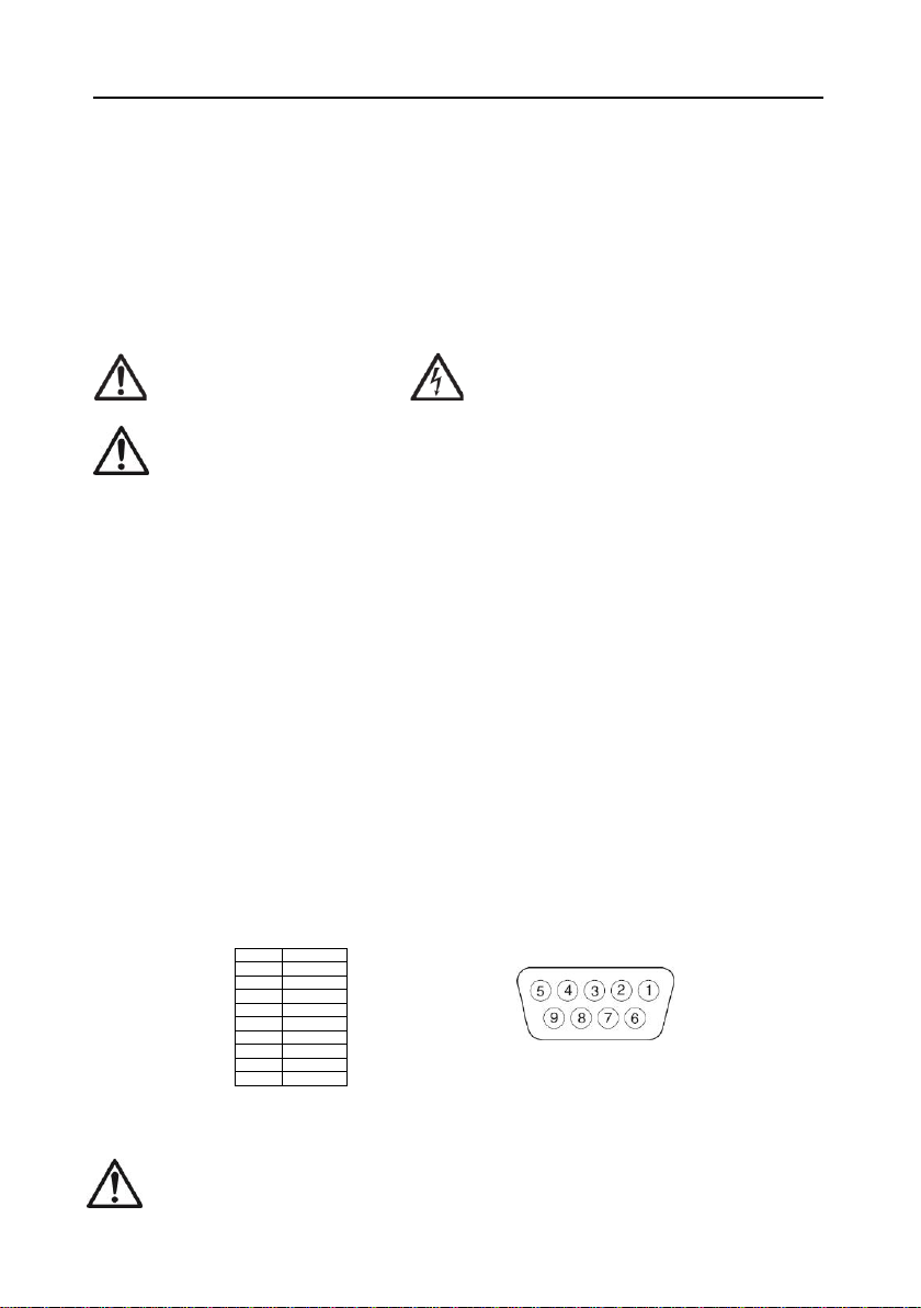
2.1 Ligações externas
Cabo da interface RS232
Ligue o cabo RS232 opcional ao conector RS232.
Pino
Ligação
1
N/C
2
TXD
3
RXD
4
N/C
5
GND
6
N/C
7
N/C
8
N/C
9
N/C
Suporte de montagem
Alinha o suporte da montagem sobre os orifícios roscados em ambos os lados do indicador e instale os puxadores. Ajuste o
indicador ao ângulo desejado e aperte os puxadores.
Atenção: Utilize apenas um adaptador de CA especificado pela OHAUS

PT-2 INDICADORES DA SÉRIE 3000
2.2 Ligações internas
Algumas ligações necessitam que o compartimento esteja aberto.
AVISO: EXISTEM PERIGOS DE CHOQUE ELÉTRICO NO INTERIOR DO COMPARTIMENTO. O COMPARTIMENTO SÓ DEVE
SER ABERTO POR PESSOAL AUTORIZADO E QUALIFICADO. RETIRE TODAS AS LIGAÇÕES ELÉTRICAS DA UNIDADE
ANTES DE ABRIR.
Abertura do compartimento
Retire os quatro parafusos de cabeça Phillips do compartimento posterior. Retire o compartimento dianteiro cuidadosamente
para não perturbar as ligações internas. Após realizar todas as ligações, volte a instalar o compartimento dianteiro.
Ligar àbase da balança
Passe o cabo da célula de carga através do redutor de tensão e instale-o no bloco de terminais J7.
Volte a apertar o redutor de tensão para garantir um vedante estanque.
Pino
Ligação
J7-1
Excitação +
J7-2
Deteção +
J7-3
Sinal +
J7-4
GND
J7-5
Sinal -
J7-6
Deteção -
J7-7
Excitação -
Ligações do comutador de derivação
Relativamente a uma célula de carga de 4 fios sem fios de deteção: os comutadores de derivação W1 e W2 devem estar
protegidos contra curto-circuitos.
Relativamente a uma célula de carga de 6 fios com fios de deteção (consulte a figura): os comutadores de derivação W1 e
W2 devem
estar abertos.
Relativamente às células de carga com um fio de ligação àterra blindado adicional: ligue a blindagem àposição central
(GND)
de J7.
Após concluir a ligação dos fios e de instalar os comutadores de derivação no local correto, substitua os pernos do
compartimento do indicador. Certifique-se de que o redutor de tensão estáapertado corretamente.

PT-3
3. FUNCIONAMENTO
3.1 Visão geral do visor, ecrãinicial
T32MC:
T32ME:
Item
Description
1
Capacity label window
2
Pound Indicator
3
Ounce indicator
4
Kilogram, gram indicator
5
TARE Menu button
6
Calibration mode indicator
7
Function mode button
8
NET indicator
9
PCS indicator
10
Print units button
11
Accumulation indicator
12
Hold indicator
13
ON/ZERO Off button
14
Center of Zero indicator
15
Under LED
16
Accept LED
17
Over LED
18
Stable weight indicator
Item
Description
1
Capacity label window
2
Gram Indicator
3
Kilogram indicator
4
Pound indicator
5
Ounce indicator
6
Tare menu indicator
7
Calibration mode indicator
8
NET indicator
9
Function mode button
10
PCS indicator
11
Accumulation indicator
12
Hold indicator
13
Print units button
14
Stable weight indicator
15
ON/ZERO off button
16
Center of Zero indicator
17
Under LED
18
Accept LED
19
Over LED

PT-4 INDICADORES DA SÉRIE 3000
Funções de controlo
Botão
On/Zero
Off
Yes
Print
Units
No
Function
Mode
Back
Tare
Menu
Exit
Função principal
(Premir breve)
ON/ZERO
(LIGAR/ZERO)
Liga o indicador.
Coloca o visor a zeros.
PRINT (IMPRIMIR)
Envia o valor exibido
para a porta de
comunicação.
FUNCTION (FUNÇÃO)
Inicia a função do modo de
aplicação atual.
TARE (Tara)
Realiza o funcionamento da tara.
Função secundária
(Premir longo)
Off (Desligar)
Desliga o indicador.
Units (Unidades)
Altera a unidade de
pesagem.
Mode (Modo)
Permite a alteração do
modos de aplicação.
Manter premido permite
percorrer os modos.
Menu
Entra no menu.
Visualiza os contadores de
eventos da pista de auditoria
(manter premido)
Função de menu
(Premir breve)
Yes (Sim)
Aceita o menu ou a
definição atual.
No (Não)
Avança para omenu ou
definição seguinte.
Aumenta o valor exibido.
Back (Voltar)
Retrocede para omenu ou
definição anterior.
Reduz o valor exibido.
Exit (Sair)
Sai do menu.
Cancela a calibração em curso.
Placa de circuito impresso principal

PT-5
3.2 Estrutura do menu
4. MANUTENÇÃO.
4.1 Limpeza
AVISO: Risco de choque elétrico. Desligue o equipamento da fonte de alimentação antes de limpar.
Certifique-se de que não entra nenhum líquido para o interior do instrumento.
Atenção: Não utilize solventes, produtos químicos abrasivos, amoníaco ou agentes abrasivos.
As superfícies exteriores do instrumento podem ser limpas com um pano humedecido com água e um detergente neutro.
4.2 Resolução de problemas
Para problemas técnicos, entre em contacto com um agente de serviço autorizado da Ohaus. Visite o nosso site Web
www.ohaus.com para localizar o estabelecimento Ohaus mais próximo de si.

PT-6 INDICADORES DA SÉRIE 3000
5. DADOS TÉCNICOS
Os dados técnicos são válidos sob as seguintes condições:
Apenas para utilização interior.
Temperatura de funcionamento: -10 °C a 40 °C.
Humidade relativa: humidade relativa máxima de 80 % para temperatura até31 °C, diminuindo a linearidade da
humidade relativa para 50% a 40 °C.
Altitude: Até2000 m.
Flutuações de tensão da fonte de alimentação: até±10% da tensão nominal.
Grau de poluição: 2
Categoria de instalação: II
ESPECIFICAÇÕES:
Modelo
T32MC
T32ME
Intervalo de capacidade
5 to 20000 kg or lb
Resolução máxima exibida
1:20,000
Tipo de resolução aprovada
1:6,000
Tensão de excitação da célula
de carga
5 VDC
Acionamento da célula de carga
Up to 4 x 350 ohm load cells
Sensibilidade da entrada de
célula de carga
Up to 3 mV/V
Alimentação
9 - 12VDC, 0.5A, AC
6. CONFORMIDADE
A conformidade com as seguintes normas estáindicada pela marca correspondente no produto.
Marca
Norma
Este produto cumpre com as diretivas da UE 2014/30/UE (EMC), 2014/35/UE (LVD) e 2014/31/UE
(NAWI). A Declaração de Conformidade da UE estádisponível online em www.ohaus.com/ce.
Este produto cumpre com a diretiva da UE 2002/96/CE (REEE). Elimine este produto de acordo com os
regulamentos locais no ponto de recolha especificado para o equipamento elétrico e eletrónico. Para
instruções de eliminação na Europa, consulte www.ohaus.com/weee.
Instrumentos de pesagem verificados
Quando o instrumento éutilizado no comércio ou numa aplicação legalmente controlada, deve ser preparada, verificada e
selada de acordo com os regulamentos dos pesos e medidas locais. Éda responsabilidade do comprador garantir que todos
os regulamentos legais pertinentes são cumpridos.
Os instrumentos de pesagem verificados no local do fabrico possuem a seguinte marcação metrológica suplementar na placa
de identificação.
Os instrumentos de pesagem a serem verificados em duas fases não possuem marcação metrológica suplementar na placa
de identificação. A segunda fase da avaliação da conformidade deve ser realizada pelas autoridades aplicáveis dos pesos e
medidas.
Se os regulamentos nacionais limitarem o período da validade da verificação, o utilizador do instrumento de pesagem deve
observar estritamente o período da nova verificação e informar as autoridades dos pesos e medidas
Como os requisitos de verificação variam de acordo com a jurisdição, o comprador deve entrar em contacto com o
departamento local dos pesos e medidas se não estiver familiarizado com os requisitos.

SV-1
1. SÄKERHETSINFORMATION
Definition av Signal Varningar och Symboler
VARNING För en farlig situation med medelhög risk, vilket kan leda till skador eller dödsfall om den inte
undviks.
FÖRSIKTIGHET För en farlig situation med låg risk, vilket resulterar i skador påenheten eller egendom eller förlust
av data, eller småeller medelstora skador om den inte undviks.
Uppmärksamhet För viktig information om produkten.
Notering Användbar information om produkten.
Varnings Symboler
Allmän fara
Elektrisk Stöt
Säkerhetsåtgärder
FÖRSIKTIGHET: Läs alla säkerhetsvarningar innan du installerar, gör anslutningar eller servar denna
utrustning. Underlåtenhet att efterkomma dessa varningar kan resultera i personskada och / eller
egendomsskador. Behåll alla instruktioner för framtida referens.
Kontrollera att den lokala växelmatningsspänningen ligger inom inspänningsområdet tryckt påelnätskabelns graderings
etikett.
Anslut endast elnätskabeln till ett kompatibel jordat uttag.
Placera instrumentet såatt elnätkabeln lätt kan kopplas ur vägguttaget.
Placera nätsladden såatt den inte utgör ett potentiellt hinder eller snubbelrisk.
Använd utrustningen endast under de omgivningsförhållanden som anges i användningsanvisningen.
Använd inte utrustningen i farliga eller explosiva miljöer.
Koppla bort utrustningen från elnätet före rengöring eller underhåll.
Service får endast utföras av auktoriserad personal.
Avsedd användning
Använd instrumentet enbart för de syften som beskrivs i handboken. All annan typ av användning och drift utanför gränserna
för de tekniska specifikationer utan skriftligt medgivande från OHAUS, betraktas som inte avsedd.
Detta instrument uppfyller gällande branschstandarder och erkända säkerhetsbestämmelser; men det kan utgöra en fara i
bruk.
Om instrumentet inte används i enlighet med dessa användarinstruktioner, kan skydd av instrumentet försämras och OHAUS
tar inget ansvar.
2. INSTALLATION
2.1 Externa Anslutningar
RS232 Gränssnitts Kabel
Anslut RS232-kabeln till RS232-anslutningen.
Pin
Anslutning
1
N/C
2
TXD
3
RXD
4
N/C
5
GND
6
N/C
7
N/C
8
N/C
9
N/C
ACStröm Installation
Anslut AC elnätkabeln till instrumentets strömingång, och anslut sedan nätkontakten till ett lämpligt eluttag.
Attention: Använd endast en nätadapter anges av OHAUS

SV-2 3000 SERIES INDIKATORER
Fästning av Monteringsfästet
Placera väggfästet över de gängade hålen påvarje sida av indikatorn och installera knopparna. Justera indikatorn till önskad
vinkel och dra åt knopparna.
2.2 Interna Anslutningar
Vissa anslutningar kräver att höljet öppnas.
VARNING: ELEKTRISK RISK FÖR STÖTAR INUTI HUSET. HÖLJET FÅR ENDAST ÖPPNAS AV
AUKTORISERAD OCH KVALIFICERAD PERSONAL. TA BORT ALLA STRÖMANSLUTNINGAR TILL
ENHETEN INNAN DEN ÖPPNAS.
Öppna Höljet
Ta bort de fyra stjärnskruvarna från det bakre huset. Försiktigt ta bort det främre huset såatt inte störa de interna
anslutningarna. När alla anslutningar är gjorda sätter du tillbaka främre huset.
Connecting the Scale Base
Pass the load cell cable through the strain relief and attach it to terminal block J7.
Re-tighten the strain relief to ensure a watertight seal.
Pin
Anslutning
J7-1
+ Excitation
J7-2
+ Sense
J7-3
+ Signal
J7-4
GND
J7-5
–Signal
J7-6
–Sense
J7-7
–Excitation
Bygel anslutningar
För en 4-trådslastcell utan sinnes trådar: Byglarna W1 och W2 måste kortslutas.
För en 6-trådslastcell som innehåller sinnes kablar: Byglarna W1 och W2 måste öppnas.
För lastceller med en extra jordningsskydd tråd: Anslut jordtråden i mittläget (GND) av J7.
Efter ledningsdragning är slutförd och byglar finns påplats, byt indikatorhöljets skruvar. Se till att dragavlastningen är
ordentligt åtdragna.

SV-3
3. ANVÄNDNING
3.1 Översikt av Bildskärm och Kontroller
T32MC:
T32ME:
Item
Description
1
Capacity label window
2
Pound Indicator
3
Ounce indicator
4
Kilogram, gram indicator
5
TARE Menu button
6
Calibration mode indicator
7
Function mode button
8
NET indicator
9
PCS indicator
10
Print units button
11
Accumulation indicator
12
Hold indicator
13
ON/ZERO Off button
14
Center of Zero indicator
15
Under LED
16
Accept LED
17
Over LED
18
Stable weight indicator
Item
Description
1
Capacity label window
2
Gram Indicator
3
Kilogram indicator
4
Pound indicator
5
Ounce indicator
6
Tare menu indicator
7
Calibration mode indicator
8
NET indicator
9
Function mode button
10
PCS indicator
11
Accumulation indicator
12
Hold indicator
13
Print units button
14
Stable weight indicator
15
ON/ZERO off button
16
Center of Zero indicator
17
Under LED
18
Accept LED
19
Over LED

SV-4 3000 SERIES INDIKATORER
Kontroll Funktioner
Knapp
On/Zero
Off
Yes
Print
Units
No
Function
Mode
Back
Tare
Menu
Exit
Primär Funktion
(Kort Tryck)
ON/ZERO
Sätt påindikatorn.
Nollställa displayen
PRINT
Skicka det visade
värdet till COM-
porten.
FUNCTION
Påbörja det aktuella
programmetläges
funktion
TARE
Utför en tare operation
Sekundär
Funktion
(Lång Tryck)
Off
Stäng indikatorn
Units
Ändra viktsenheten
Mode
Ändra programläge
Menu
Gåin i menyn.
Visa verifieringskedjan
händelseräknare (förlängt
tryck)
Meny Funktion
(Kort Tryck)
Yes
Acceptera aktuell
meny eller
inställning
No
Gåvidare till nästa
meny eller
inställning.
Öka det visade
värdet
Back
Gåtillbaka till
föregående meny eller
inställning.
Sänka det visade
värdet
Exit
Lämna menyn.
Avbryt kalibreringen pågår.
Huvud Kretskortet

SV-5
3.2 Meny Struktur
4. UNDERHÅLLNING
4.1 Rengöring
VARNING: Elektrisk Stöt Risk. Koppla bort instrumentet från strömförsörjningen före rengöring.
Se till såatt ingen vätska kommer in i instrumentets inre.
Uppmärksamhet: Använd ej lösningsmedel, kemikalier, ammoniak eller slipande rengöringsmedel.
De yttre ytorna påinstrumentet kan rengöras med en fuktig trasa med vatten och ett milt rengöringsmedel.
4.2 Felsökning
För tekniska problem kontakta en godkänd OHAUS service agent. För tekniska frågor kontakta ett auktoriserat OHAUS
serviceombud. Besök gärna vår hemsida www.OHAUS.com för att hitta OHAUS kontoret närmast dig.
5.TEKNISK DATA
Den tekniska datan är giltig under följande villkor:
Endast inomhusbruk.
Arbetstemperatur: –10°C to 40°C
Relativ fuktighet: maximal relativ fuktighet 80 % för temperaturer upp till 31 °C, minskar linjärt till 50% relativ fuktighet
vid 40 °C.
Alltitud: Upp till 2000 m.
Nätspännings fluktuationer: upp till ±10% av nominell spänning
Föroreningsgrad: 2
Installations Kategori: II

SV-6 3000 SERIES INDIKATORER
Specifikationer:
Indikator Modell
T32MC
T32ME
Kapacitet räckvidd
5 to 20000 kg or lb
Maximal visade upplösning
1:20,000
Typ godkänd upplösning
1:6,000
Last cell excitation spänning
5 VDC
Last cell drift
Up to 4 x 350 ohm load cells
Lastcell inmatnings känslighet
Up to 3 mV/V
Ström
9 - 12VDC, 0.5A, AC
6. ÖVERENSSTÄMMELSE
Överensstämmelse med följande standarder indikeras av motsvarande märke påprodukten.
Märke
Standard
Denna produkt överensstämmer med EU Direktiv 2014/30/EU (EMC), 2014/35/EU (LVD) och 2014/31/EU
(NAWI). EU Deklarationen om överensstämmelse finns tillgänglig påwww.OHAUS.com/ce.
Denna produkt överensstämmer med EU Direktiv 2002/96/EC (WEEE). Vänligen kassera denna produkt i
enlighet med lokala föreskrifter vid uppsamlingspunkten angiven för elektrisk och elektronisk utrustning.
För kasserings instruktioner i Europa referera till www.OHAUS.com/weee.
Kontrollerade instrument
När instrumentet används i yrkesmässig verksamhet eller en rättslig kontrollerad tillämpning måste det ställas in, kontrolleras
och förseglas i enlighet med lokala mått och vikt regler. Det är köparens ansvar att se till att alla relevanta rättsliga krav
uppfylls.
Instrument som kontrollerats påtillverkningsplatsen är försedda med följande tilläggsmärkning påden beskrivande plattan.
Instrument som ska kontrolleras i tvåsteg har inga metrologiska tilläggsmärkningen påden beskrivande plattan.
Det andra steget i bedömningen av överensstämmelse skall utföras av de gällande vikt och mått myndigheter.
Om nationella bestämmelser begränsar giltighetstiden för kontrollen, måste användaren av instrumentet noggrant följa
återverifieringsperiod och informera vikt och mått myndigheter
Dåkontrollkraven varierar beroende påjurisdiktion, ska köparen kontakta sitt lokala mått och vikt kontor om de inte är
bekanta med kraven.
Other manuals for Ranger 3000 Series
14
This manual suits for next models
2
Table of contents
Languages:
Other OHAUS Touch Panel manuals

OHAUS
OHAUS CKW-55 User manual

OHAUS
OHAUS T32ME User manual

OHAUS
OHAUS T21P User manual

OHAUS
OHAUS DEFENDER 7000 XtremeW Series User manual

OHAUS
OHAUS T51P User manual

OHAUS
OHAUS TD52 User manual

OHAUS
OHAUS Ranger 3000 Series User manual

OHAUS
OHAUS Ranger 3000 Series User manual

OHAUS
OHAUS CD-31 User manual

OHAUS
OHAUS T71P User manual