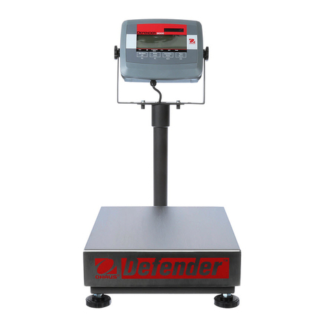
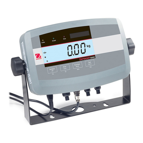
OHAUS T21P User manual

T21P Indicator
Instruction Manual
Indicador T21P
Manual de instrucciones
Indicateur T21P
Manuel d’instructions
T21P-Indikator
Bedienungsanleitung
Indicatore T21P
Manuale di istruzioni
Calidad & Servicio, Razones de Peso
Calle 23B No. 81A - 62 Modelia PBX: (571) 410 28 48 Fax: (571) 263 72 24 Bogota, D.C. - Colombia.
www.tecnipesaje.com [email protected]m [email protected]

Calle 23B No. 81A - 62 Modelia PBX: (571) 410 28 48 Fax: (571) 263 72 24 Bogota, D.C. - Colombia.
www.tecnipesaje.com [email protected]m [email protected]
Calidad & Servicio, Razones de Peso
Calle 23B No. 81A - 62 Modelia PBX: (571) 410 28 48 Fax: (571) 263 72 24 Bogotá, D.C. - Colombia.
www.tecnipesaje.com [email protected] tecnipesaje@outlook.com
HQ&RORPELD

T21P Indicator EN-1
1. INTRODUCTION
This manual contains installation, operation and maintenance instructions for the
T21P Indicator. Please read this manual completely before installation and
operation.
1.1 Safety Precautions
For safe and dependable operation of this equipment, please comply
with the following safety precautions:
• Verify that the input voltage range printed on the data label matches the local AC
power to be used.
• Make sure that the power cord does not pose a potential obstacle or tripping
hazard.
• Use only approved accessories and peripherals.
• Operate the equipment only under ambient conditions specified in these
instructions.
• Disconnect the equipment from the power supply before cleaning.
• Do not operate the equipment in hazardous or unstable environments.
• Do not immerse the equipment in water or other liquids.
• Service should only be performed by authorized personnel.
1.2. Overview of Parts and Controls
4
1
2
6
35
Calle 23B No. 81A - 62 Modelia PBX: (571) 410 28 48 Fax: (571) 263 72 24 Bogota, D.C. - Colombia.
www.tecnipesaje.com [email protected] tecnipes[email protected]

EN-2 T21P Indicator
7 9
8
10
11
Figure 1-1. T21P Indicator.
TABLE 1-1. PARTS AND CONTROLS
Item Description
1AC LED
2Low bat LED
3Zero, Tare, Stable, Accum, Pcs, Unit LEDs
47-segment, 6 digit LED display
5Control Buttons
6Over, Under, Accept LEDs
7On/Off Power Switch
8Power receptacle
9RS232 Connector
10 Load Cell connector
11 Column Bracket
Calle 23B No. 81A - 62 Modelia PBX: (571) 410 28 48 Fax: (571) 263 72 24 Bogota, D.C. - Colombia.
www.tecnipesaje.com [email protected] tecnipes[email protected]

T21P Indicator EN-3
1.2. Control Functions
TABLE 1-2. CONTROL FUNCTIONS.
Button
Primary Function
(Short Press) N/A SAMPLE
Enters Sample Setup
Saves APW
ZERO
Sets zero
Secondary Function
(Long Press) SET
Enters Menu Mode
Enters Calibration
Menu during
startup
APW
Displays APW Value
N/A
Menu Function
(Short Press)
Saves Settings and
exits the menu N/A
ENTER
Accepts the
current setting on
the display
Button
Primary Function
(Short Press) TARE
Tares weight of
item on pan
M+
Stores displayed weight
in accumulation
memory
Displays accumulation
data when display is
zero
PRINT
Sends the current
value to the
RS232 Interface
Secondary Function
(Long Press) N/A N/A
MODE
Change between
weighing and
counting mode
Menu Function
(Short Press)
ª
Decrement value
of settings
©
Increment value of
settings
¨
Shift to next digit
when setting
parameters
Calle 23B No. 81A - 62 Modelia PBX: (571) 410 28 48 Fax: (571) 263 72 24 Bogota, D.C. - Colombia.
www.tecnipesaje.com [email protected] tecnipes[email protected]

EN-4 T21P Indicator
2. INSTALLATION
2.1 Package Contents
• Indicator Unit
• AC Power Adapter
• Load Cell Cable Connector
• Column Bracket
• Instruction Manual
2.2 External Connections
2.2.1 Load Cell Connection
Solder the load cell cable to the supplied load cell cable connector.
Figure 2-1.
V
iew of pins on
the load cell cable
connector
1
2
3
4
5
6
78
9
Pin 1 2 3 4 5 6 7 8 9
Connection SIG- SENS- N/C N/C GND SENS+ EXC+ EXC- SIG+
NOTE: To use a 4 wire load cell cable you must short pin 2 to 8, and pin 6 to 7.
heCAUTION: Never connect a communication cable to the load cell connector of t
indicator. Switch the indicator off when you insert or remove the load cell cable
connector from the indicator.
NOTE:The load cell cable connector cannot pass through the supplied column
bracket. Connect the load cell cable connector to the load cell cable
after
routing the
cable through the column and column bracket. See section 2.2.5 for details.
2.2.2 RS232 Interface Connection
Pin Connection
1N/C
2TXD
3RXD
4N/C
5GND
6-9 N/C
1
2
3
4
5
6
78
9
Figure 2-2. View of RS232 Pins on
indicator. (Item 9 in Figure 1-1)
Calle 23B No. 81A - 62 Modelia PBX: (571) 410 28 48 Fax: (571) 263 72 24 Bogota, D.C. - Colombia.
www.tecnipesaje.com [email protected] tecnipes[email protected]

T21P Indicator EN-5
2.2.3 AC Power
Connect the AC Adaptor to the power receptacle, and then plug the AC Adapter into a
properly grounded electrical outlet. The AC LED will light (Figure 1-1, item 1).
Power
Receptacle
Figure 2-3. Power Connection
2.2.4 Battery Power
The indicator can be operated on the internal rechargeable battery when AC power is
not available. The indicator will automatically switch to battery operation if there is a
power failure or the power cord is removed.
NOTE: Before using the scale for the first time, the battery should be fully
charged for up to 12 hours. The indicator can be operated during the
charging process. The battery is protected against over charging and the
indicator can remain connected to the AC power line.
The indicator can operate up to 30 hours on a fully charged battery.
The indicator automatically enters standby mode after 1 minute of no activity. The
display will only show the decimal point [ . ]. Press on the pan or any key to
resume.
During battery operation, the Low Bat LED will illuminate when the battery is low and
requires recharging. Approximately 30 minutes of operation will remain. The
indicator will automatically turn off when the battery is fully discharged.
CAUTION: The battery is to be replaced only by an authorized Ohaus
service dealer. Risk of explosion can occur if the battery is replaced with
the wrong type or is connected improperly.
Dispose of the lead acid battery according to local laws and regulations.
Calle 23B No. 81A - 62 Modelia PBX: (571) 410 28 48 Fax: (571) 263 72 24 Bogota, D.C. - Colombia.
www.tecnipesaje.com [email protected] tecnipes[email protected]

EN-6 T21P Indicator
2.2.5 Mounting Column Bracket
The Indicator can be mounted to a scale column of 38mm outside diameter with the
supplied column bracket.
1. Route the cable through the column and the column bracket.
2. Slide the column bracket down onto the column and tighten the nut.
3. Solder the load cell cable to supplied load cell cable connector (see section
2.2.1).
4. Slide the indicator onto the bracket as shown below.
5. Plug the load cell cable into the indicator load cell connector Figure 1-1,
Item 10.
6. Remove the upper knob to change the viewing angle, re-install the knob to
fix the position.
3
1
5
4
2
2.3 Opening the Housing
CAUTION: ELECTRICAL SHOCK HAZARD. REMOVE ALL POWER
CONNECTIONS TO THE INDICATOR BEFORE SERVICING OR MAKING
INTERNAL CONNECTIONS. THE HOUSING SHOULD ONLY BE OPENED
BY AUTHORIZED AND QUALIFIED PERSONNEL, SUCH AS AN ELECTRICAL
TECHNICIAN.
2.4 Initial Setup and Calibration
Once properly assembled and powered up, set up the scale parameters (Section 4)
and calibrate (Section 5).
Calle 23B No. 81A - 62 Modelia PBX: (571) 410 28 48 Fax: (571) 263 72 24 Bogota, D.C. - Colombia.
www.tecnipesaje.com [email protected] tecnipes[email protected]

T21P Indicator EN-7
3. OPERATION
3.1 Turning Scale On/Off
To turn the scale on, toggle the switch on the right side of the indicator to the on
position. The scale performs a display test, momentarily displays software version,
and then enters the active weighing mode. To turn the scale off, toggle the switch to
the off position.
3.2 Zero Operation
Zero is set under the following conditions:
• Automatically at Power On (initial zero). Refer to section 4.3 [F1-2] for settings.
• Manually by pressing the ZERO button.
Press the ZERO button to zero the weight display. The scale must be stable and
within the zero range. Refer to section 4.3 [F1-0].
3.3 Manual Tare
Place a container on the weighing pan, then press TARE. The display will show a net
value of “0”. To clear the Tare value, press TARE with the pan empty.
Tare capacity is user selectable (Section 4.2).
3.4 Weighing Mode
Use this mode to measure the weight of a sample in the selected unit of measure.
Press ZERO to set the display to zero. Put an empty container on the pan, and then
press TARE to tare the container weight. Add material to the container. The display
shows the weight of the material in the selected unit of measure. See Section 4.3
[F1-3]to change the unit of measure.
3.5 Counting Mode
Use this mode to count parts of uniform weight.
When in weighing mode press SAMPLE to set the sample size.
[p00010] or the last used value will be displayed.
Press ¨, ª, ©to edit the sample size.
Place the displayed quantity of samples on the scale or tared container.
Press SAMPLE to calculate the Average Piece Weight (APW) and enter counting
mode or press ENTER to exit to weighing mode without saving changes.
Calle 23B No. 81A - 62 Modelia PBX: (571) 410 28 48 Fax: (571) 263 72 24 Bogota, D.C. - Colombia.
www.tecnipesaje.com [email protected] tecnipes[email protected]

EN-8 T21P Indicator
Long press MODE to toggle between counting and weighing modes. The Pcs LED
will illuminate to indicate counting mode.
Place parts on the scale or a tared container and read the count.
Press ZERO or SAMPLE to exit to weighing mode.
To display the APW value, exit to weighing mode and then press and hold APW. The
display will show [APwW] and [xxxxxx], where x= APW value, and will return to
weighing mode.
3.6 Weight Accumulate Mode
Use this mode to store the weight and HI, LO, SUM statistics from a series of
samples.
Place the sample on the pan or tared container.
Press M+ to store the weight of the sample. Storage is confirmed by the display
[n x], where x is the total number of samples. The Accum LED will illuminate to
let the user know there are readings in memory. Remove the sample, wait for stable
zero reading, then place the next sample on the pan. Press M+ to store the weight of
the next sample. Repeat this process until all samples have been weighed.
Review the accumulation data by pressing M+ when the display is at zero.
The display shows the total number of samples [n x].
Press M+ to view the maximum sample weight [Hxxxxx].
Press M+ to view the minimum sample weight [Lxxxxx].
Press M+ to view the sum of the weights [xxxxxx].
Press M+ to return to weighing.
To clear the accumulated data press ZERO when the number of samples [n x]
is displayed.
NOTE: A total of 999 accumulation records [n 999] can be stored. The sum of
the weights cannot exceed [999999]. The indicator displays [n_Over] or
[a_Over] if these values are exceeded. Clear the accumulated data to continue
Calle 23B No. 81A - 62 Modelia PBX: (571) 410 28 48 Fax: (571) 263 72 24 Bogota, D.C. - Colombia.
www.tecnipesaje.com [email protected] tecnipes[email protected]

T21P Indicator EN-9
3.7 Check Weigh Mode
Use this mode to compare samples to a target weight range.
Under = weight is below preset minimum value.
Accept = weight is equal or within preset target range.
Over = weight exceeds preset maximum value.
Refer to Section 4.2 to enable check weigh, to select the alarm and to set limits.
3.8 Changing Units of Measure
Only one unit can be active at any time (kg or lb).
To select the active unit enter the User Settings Menu [F1-3] (Section 4.3).
NOTE: When selecting ‘lb’, make sure to apply the supplied ‘lb’ label over the ‘kg’
text on the overlay.
Calle 23B No. 81A - 62 Modelia PBX: (571) 410 28 48 Fax: (571) 263 72 24 Bogota, D.C. - Colombia.
www.tecnipesaje.com [email protected] tecnipes[email protected]

EN-10 T21P Indicator
4. SETTINGS
4.1 Menu Mode and Navigation
To enter the Menu Mode
Press and hold the SET button for 3 seconds.
[SET-Fx] will be displayed where x =:
0= set upper and lower limit value.
1= User Settings Menu.
2= restores settings to factory default.
3= set tare capacity between 2/3Max. and full scale.
To navigate in the Menu Mode:
Press ¨to toggle through available settings.
Press ENTER to accept the displayed setting and advance to the next step.
Press SET at any time to save settings and return to weighing.
4.2 Set Upper and Lower Limit Values
Enter the Menu Mode (Section 4.1). [SET-F0] will be displayed.
Press ENTER to accept the displayed setting and view the upper limit [000000].
The Over LED will illuminate.
Press ¨, ª, ©to edit the upper limit.
Press ENTER to confirm the setting and display the lower limit [000000].
The Under LED will illuminate.
Press ¨, ª, ©to edit the lower limit.
Press ENTER to confirm the setting and the display will show the alarm setting
[rUn X], where x=:
0 = check weigh mode is disabled.
1 = under / accept / over LEDs are active, the beeper will sound when the weight
is outside the accept range.
2 = under / accept / over LEDs are active, the beeper will sound when the weight
is within accept range.
3 = under / accept / over LEDs are active, the beeper is disabled.
Press ¨to change the alarm setting.
Press ENTER to confirm setting and display the upper limit.
Press SET to store the values and return to weighing.
Calle 23B No. 81A - 62 Modelia PBX: (571) 410 28 48 Fax: (571) 263 72 24 Bogota, D.C. - Colombia.
www.tecnipesaje.com [email protected] tecnipes[email protected]

T21P Indicator EN-11
4.3 User Settings Menu
Enter the Menu Mode (Section 4.1) and press ¨to display [SET-F1].
Press ENTER to accept the displayed setting.
Parameters Description Settings of “x”
[F1-0 x] Zero Range 0= 2% of max (default)
1= 5% of max
2= 10% of max
3= 20% of max
[F1-1 x] Zero Tracking
Range
0= 0 division
1= 0.5 division (default)
2= 1 division
3= 2 division
4= 3 division
5= 4 division
6= 5 division
[F1-2 x] Initial Zero 0= 10% of max
1= 20% of max
2= 50% of max (default)
3= 100% of max
[F1-3 x] Measuring
Unit
0= kg (default)
1= lb
[F1-4 x] Filter Level 0= Low
1= Medium (default)
2= High
3= Maximum
[F1-5 x] Stability
Indication
0= Fast
1= High (default)
2= Medium
3= Slow
[F1-6 x] Baud Rate* 0= 9600 (default)
1= 4800
2= 2400
3= 1200
Calle 23B No. 81A - 62 Modelia PBX: (571) 410 28 48 Fax: (571) 263 72 24 Bogota, D.C. - Colombia.
www.tecnipesaje.com [email protected] tecnipes[email protected]

EN-12 T21P Indicator
Parameters Description Settings of “x”
[F1-7 x] RS232C
Output Mode*
0= output Gross, Net, Tare on PRINT key press
only (default)
1= output G.N.T., transmit continuously
2= output G.N.T., transmit continuously after
stable.
*NOTE: RS232 setting changes will not be active until
SET key is pressed to store data; return to weigh mode
and the indicator is turned off and turned on again.
[F1-8 0] Not active Not active
[F1-9 x] Display
Brightness
0= low
1= medium (default)
2= high
3= maximum
[F1-a x] Accumulation
Zero Band
Accumulation key M+ is effective when stable
weight returns to within x=:
0= 0 division (default)
1= 0 to 1d
2= 0 to 2d
3= 0 to 5d
4= 0 to 10d
4.4 RESTORE SETTINGS TO DEFAULT
Enter the Menu Mode (Section 4.1) and press ¨to display [SET-F2]
Press ENTER to accept the displayed setting.
The default settings will be shown.
Press SET to save the default values and exit to weigh mode.
You must turn off the indicator for the changes to be effective.
The default settings will be active when the indicator is turned on.
4.5 SET TARE CAPACITY
Enter the Menu Mode (Section 4.1) and press ¨to select [SET-F3].
Press ENTER to accept the displayed setting.
Parameters Description Settings of “x”
[Set-f3] Tare Capacity 0= tare capacity is 2/3 Max (default)
1= tare capacity is max
Press ª, ©to toggle through available settings.
Press ENTER to confirm.
Press SET to store values and return to weighing.
Calle 23B No. 81A - 62 Modelia PBX: (571) 410 28 48 Fax: (571) 263 72 24 Bogota, D.C. - Colombia.
www.tecnipesaje.com [email protected] tecnipes[email protected]

T21P Indicator EN-13
5. SCALE SETUP AND CALIBRATION
NOTES:
1. Make sure that appropriate calibration kilogram masses are available
before beginning calibration.
2. Make sure that the scale base is level and stable during the entire
calibration process.
3. Allow the Indicator to warm up for approximately 5 minutes after stabilizing
to room temperature.
4. To abort calibration, press and hold the SET button for 3 seconds anytime
during the calibration process. Or turn unit off.
Turn on the indicator. During startup display sequence press and hold SET until
[FS__SP]is displayed.
Press ENTER to display [P___x] (x=position of decimal point: 0, 1, 2, 3, and 4).
Press ª, ©to select the desired setting.
Press ENTER to display [D___x] (x=divisions: 1, 2,5,10, 20, and 50).
Press ª, ©to select the division.
Press ENTER to display Maximum Capacity Setting.
Press ¨, ª, ©to set the desired value.
The LED row below the display refers to the active segment.
Press ENTER to accept and [noLoad] is displayed.
Make sure pan is empty.
Press ENTER to accept and [Load] is displayed.
Press ENTER to display [xxxxxx] (xxxxx= Span Weight).
Press ¨, ª, ©to set a different value
Place calibration weight on the pan
Press ENTER to accept and store data.
[CALEnd] will be displayed for 2 seconds and the indicator will enter weighing
mode.
Calle 23B No. 81A - 62 Modelia PBX: (571) 410 28 48 Fax: (571) 263 72 24 Bogota, D.C. - Colombia.
www.tecnipesaje.com [email protected] tecnipes[email protected]

EN-14 T21P Indicator
6. SERIAL COMMUNICATION
The Indicator includes an RS232 serial communication interface. The setup of
RS232 operating parameters are more fully explained in Section 4.3 [F1-6] and
[F1-7]. The physical hardware connection is explained in Section 2.2.2.
The interface enables display data to be sent to a computer or printer.
6.1 OUTPUT FORMAT
The default serial output format is shown below.
Field: Space Polarity Weight Unit Stability Legend CR LF
Length: 2 1 7 2 1 1 1 1
Example:
- 3 8 . 5 6 0 k g / G
Definitions:
Polarity, “-“ sign if negative, blank if positive.
Weight, up to 6 numbers and 1 decimal, right justified, leading zero blanking.
Units, up to 2 characters.
Stability, “/” character is printed if not stable, blank if stable.
Legend, up to 3 characters: G= gross weight, N= net weight, T= tare.
Calle 23B No. 81A - 62 Modelia PBX: (571) 410 28 48 Fax: (571) 263 72 24 Bogota, D.C. - Colombia.
www.tecnipesaje.com [email protected] tecnipes[email protected]

T21P Indicator EN-15
7. MAINTENANCE
Caution: before cleaning, turn off the scale, and disconnect the AC adapter.
7.1 Cleaning
The housing may be cleaned with a cloth dampened with a mild detergent if
necessary. Do not use solvents, chemicals, alcohol, ammonia or abrasives.
7.2 Troubleshooting
The following table lists common problems and possible causes and remedies. If
the problem persists, contact Ohaus or your authorized dealer.
TABLE 7-1. TROUBLESHOOTING.
Symptom Possible Cause(s) Remedy
Scale will not turn on No power to scale •
Battery power used up
Verify connections and voltage •
Connect power and charge the
battery
Poor accuracy Improper calibration •
Unstable environment
Perform calibration •
Move scale to suitable location
Unable to calibrate Unstable environment •
Incorrect calibration mass
Move the scale to suitable location •
Use correct calibration mass
Battery fails to charge
fully
Battery is defective Have battery replaced by authorized
service dealer
Display = Zero-E Pan has excessive load during
power on •
No span calibration
Remove weight from pan and re-zero
• Perform Span Calibration
Display = 000000
or 999999; or no
weight reading
Load cell connector is
disconnected •
No calibration data in EEPROM
Connect the load cell connector •
Calibrate the indicator.
No display or AC LED
is off
Power cable or battery is defective Check power cable • Replace battery
“Low Bat” LED is lit Battery is weak Connect power cable to AC •
Charge the battery.
Display = Cou-no No sample quantity to be set Set sample quantity.
Display = L0_rEF APW is less than 0.25d Use APW >0.25d
--0ver Total weight is greater than Full
Scale + 9d
Reduce the load on the pan
n-0ver Accumulation records are greater
than 999
Clear Accumulation data
Calle 23B No. 81A - 62 Modelia PBX: (571) 410 28 48 Fax: (571) 263 72 24 Bogota, D.C. - Colombia.
www.tecnipesaje.com [email protected] tecnipes[email protected]

EN-16 T21P Indicator
Symptom Possible Cause(s) Remedy
A-0ver Total weight accumulation is
greater than displayable range
Clear Accumulation data
Ad__Lo Calibration weight exceeds
maximum displayed resolution
Change range and resolution
7.3 Service Information
If the troubleshooting section does not resolve or describe your problem, contact
your authorized Ohaus service agent. For service assistance or technical support in
the United States call toll-free 1-800-526-0659 between 8.00 AM and 5:00 PM
EST. An Ohaus product service specialist will be available to provide assistance.
Outside the USA, please visit our web site, www.ohaus.com to locate the Ohaus
office nearest you.
Calle 23B No. 81A - 62 Modelia PBX: (571) 410 28 48 Fax: (571) 263 72 24 Bogota, D.C. - Colombia.
www.tecnipesaje.com [email protected] tecnipes[email protected]

T21P Indicator EN-17
8. TECHNICAL DATA
The technical data is valid under the following ambient conditions:
Ambient temperature: -10°C to 40°C / 14°F to 104°F.
Maximum Relative humidity: 80% for temperatures up to 31°C, decreasing linearly
to 50% relative humidity at 40°C, non-condensing.
Height above sea level: Up to 2000m.
8.1 Specifications
TABLE 8-1. Specifications.
Model T21P
Housing Dimensions 250W x 142D x 180H mm (without column bracket)
Full Scale Capacity Range 5 to 20,000 kg or lb
Recommended Displayed
Resolution 1:10,000d
Minimum Average Piece
Weight (APW) 0.25d
Weighing Units Kilograms, Pounds
Functions Parts Counting, Weighing, Weight Accumulation,
Check Weighing
Sample Size User configurable up to 99,999
Display LED, (20 mm / 0.8 in high ), 6-digit 7-segment
Keypad 6 function mechanical switches, raised, tactile
Load Cell Drive Up to 4 x 350 ohm load cells
Load Cell Excitation Voltage 5V DC
Load Cell Input Sensitivity Up to 3mV/V
Stabilization Time ≤2 seconds
Auto-Zero Tracking Off, 0.5, 1, 2, 3, 4 or 5 divisions
Key Zeroing Range 2%, 5%, 10%, 20% of capacity
Span Calibration 1kg or 1lb to 100% of capacity
Interface Simplex RS232C
Power requirements 9 VDC 500 mA AC adapter (supplied)
Battery 6V 4Ah Internal rechargeable sealed lead acid battery
30-hour typical operation with 12-hour full charge
Operating Temperature Range -10°C to 40°C
Net Weight 2 kg / 4.4 lb
Shipping Weight 2.5 kg / 5.5 lb
Shipping Dimensions 320w x 210d x 236h
Calle 23B No. 81A - 62 Modelia PBX: (571) 410 28 48 Fax: (571) 263 72 24 Bogota, D.C. - Colombia.
www.tecnipesaje.com [email protected] tecnipes[email protected]

EN-18 T21P Indicator
8.2 Drawings and Dimensions
38 mm
1.48 in.
44 mm
1.72 in.
48.5 mm
1.9 in.180 mm
7 in.
142 mm
5.60 in.
250 mm
9.84 in.
Figure 8-1. T21P Indicator Overall Dimensions.
Calle 23B No. 81A - 62 Modelia PBX: (571) 410 28 48 Fax: (571) 263 72 24 Bogota, D.C. - Colombia.
www.tecnipesaje.com [email protected] tecnipes[email protected]
Table of contents
Languages:
Other OHAUS Touch Panel manuals

OHAUS
OHAUS CD-31 User manual

OHAUS
OHAUS DEFENDER 7000 XtremeW Series User manual

OHAUS
OHAUS T51P User manual

OHAUS
OHAUS T71P User manual

OHAUS
OHAUS Ranger 3000 Series User manual

OHAUS
OHAUS TD52 User manual

OHAUS
OHAUS T51P User manual

OHAUS
OHAUS 3000 Series T31P User manual

OHAUS
OHAUS CKW-55 User manual

OHAUS
OHAUS 3000 Series T32XW User manual
Popular Touch Panel manuals by other brands

Crestron
Crestron TPS-6X Series Operation guide

Beckhoff
Beckhoff CP62 Series Installation and operating instructions

Elo Touch Solutions
Elo Touch Solutions ESY15i2 user manual

Winmate
Winmate W07IB3S-PCO1AC-POE user manual

IBM
IBM Low Power 667Mhz Panel PC PPC-1510PT user manual

Elo TouchSystems
Elo TouchSystems ET1515L Series user guide