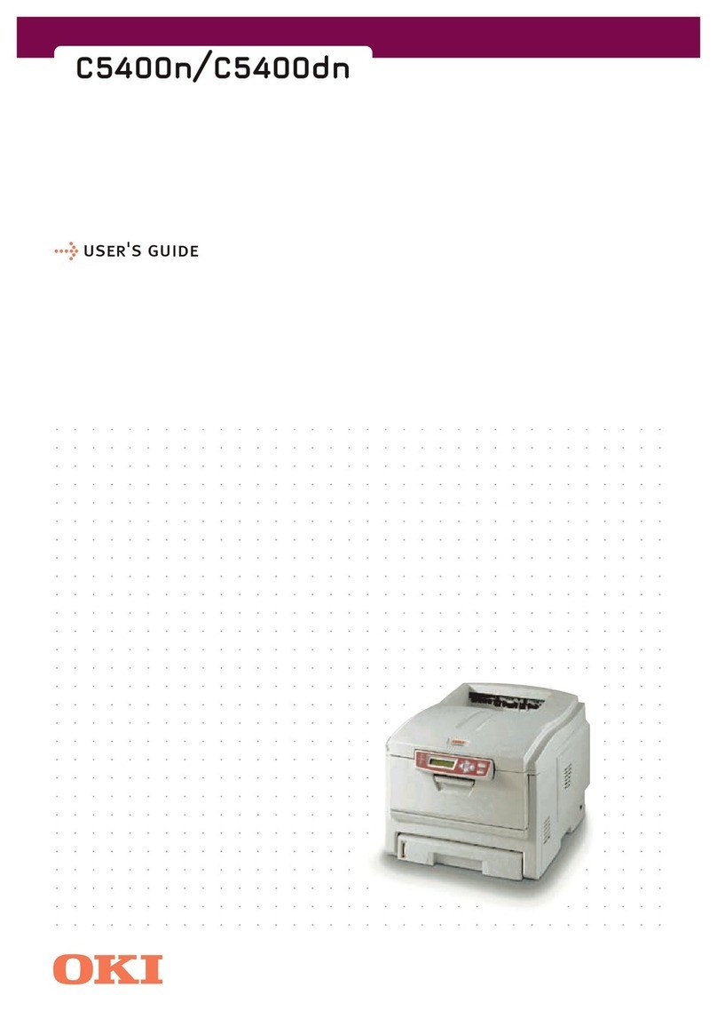
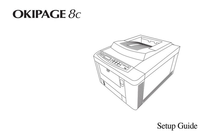
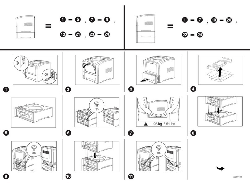
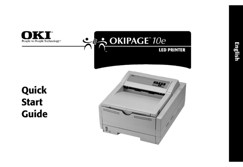
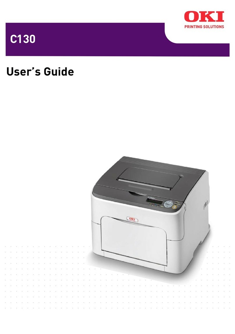
Oki B721 User manual

B721 / B731 / MPS5501b
Maintenance Manual
070813A

Copyright Information
Copyright © 2013by Oki Data. All Rights Reserved
Disclaimer
Every effort has been made to ensure that the information in this document is complete, accurate, and up-to-
date. The manufacturer assumes no responsibility for the results of errors beyond its control. The
manufacturer also cannot guarantee that changes in software and equipment made by other manufacturers and
referred to in this guide will not affect the applicability of the information in it. Mention of software products
manufactured by other companies does not necessarily constitute endorsement by the manufacturer.
While all reasonable efforts have been made to make this document as accurate and helpful as possible, we
make no warranty of any kind, expressed or implied, as to the accuracy or completeness of the information
contained herein.
The most up-to-date drivers and manuals are available from the web site:
http://www.okiprintingsolutions.com

45487001TH Rev.1 iii /
Oki Data CONFIDENTIAL
This manual explains maintenance methods for B721/B731/ES7131/MPS5501b.
The manual has been prepared for use by the maintenance personnel. For operating
methods of B721/B731/ES7131/MPS5501b, refer to the corresponding user’s manual.
Note! • Thecontentsofthismanualaresubjecttochangeswithoutpriornotice.
• Despite that exhaustive efforts were madein preparing themanual to
make it accurate, it still may contain errors. Oki Data will not hold itself
liable for any damage that results or is claimed to have resulted from repair,
adjustment,ormodicationoftheprinterconductedbytheuserusingthis
manual.
• Thepartsemployedintheprinteraresodelicatethattheymaybedamaged
if not treated properly. Oki Data Corporation highly recommends that the
maintenance of the printer is undertaken by ODC’s registered maintenance
personnel.
• Workaftereliminatingstaticelectricity.
PREFACE
PREFACE

45487001TH Rev.1 iv /
Oki Data CONFIDENTIAL
CONTENTS
CONTENTS
1. Configuration .......................................................................1-1
1.1 System configuration ......................................................................................1-2
1.2 Printer configuration ........................................................................................1-3
1.3 Composition of optional items .........................................................................1-4
1.4 Specifications...................................................................................................1-5
1.5 Interface specifications ...................................................................................1-8
1.5.1 USB interface specifications ...............................................................1-8
1.5.1.1 USB interface overview ......................................................1-8
1.5.1.2 USB interface connectors and cables ...............................1-8
1.5.1.3 USB interface signals .........................................................1-8
1.5.2 Network interface specifications .........................................................1-9
1.5.2.1 Network interface overview.................................................1-9
1.5.2.2 Network interface connector and cable .............................1-9
1.5.2.3 Network interface signals ..................................................1-9
1.5.3 USB host interface specifications .....................................................1-10
1.5.3.1 USB host interface overview ...........................................1-10
1.5.3.2 USB host interface connector...........................................1-10
1.5.3.3 USB host interface signals ...............................................1-10
1.5.4 WirelessLANinterfacespecications(WirelessModelonly)............1-10
1.5.4.1 WirelessLANinterfaceoverview......................................1-10
1.5.5 Parallel interface specifications (Parallel installed Model only)..........1-11
1.5.5.1 Parallel interface overview ..............................................1-11
1.5.5.2 Parallel interface connector and cable..............................1-11
1.5.5.3 Parallel interface signals...................................................1-11
1.5.5.4 Parallel interface levels ....................................................1-11
2. Installation............................................................................2-1
2.1 Cautions, and do’s and don’ts..........................................................................2-2
2.2 Unpacking procedure.......................................................................................2-3
2.3 Printer installation instructions .........................................................................2-4
2.4 List of components and accessories................................................................2-5
2.5 Assembly procedure ........................................................................................2-6
2.5.1 Assembly of the printer main unit ........................................................2-6
2.5.2 Connection of the AC cord ................................................................2-12
2.5.3 Installation and recognition confirmation of options ..........................2-14
2.6 Printing of the configuration report.................................................................2-28
2.7 Connection methods......................................................................................2-29
2.8 Checking of paper used by the user ..............................................................2-39
3. Component replacement.....................................................3-1
3.1 Precautions on component replacement .........................................................3-2
3.2 Method of component replacement .................................................................3-4
3.2.1 Transfer roller.......................................................................................3-4
3.2.2 Fuser unit ............................................................................................3-5
3.2.3 Cover-Rear-Blind ................................................................................3-5
3.2.4 Cover side-L .......................................................................................3-6
3.2.5 Cover side-R........................................................................................3-6
3.2.6 PU/CU-Board ......................................................................................3-7
3.2.6.1 PU/CU-Board......................................................................3-7
3.2.6.2 How to remove Battery(PU/CU-Board)...............................3-8
3.2.7 Power supply unit ................................................................................3-9
3.2.8 DC motor (hop) / DC motor (ID) ..........................................................3-9
3.2.9 Motor FAN (PSU) ..............................................................................3-10
3.2.10 Motor FAN (ID) / Micro switch ...........................................................3-10
3.2.11 HV-Board / Motor-FAN ......................................................................3-11
3.2.12 LED Assy ..........................................................................................3-11
3.2.13 Plate-Assy-Duct ................................................................................3-12
3.2.14 Frame-Assy-OP-Panel ......................................................................3-13
3.2.15 LCD panel .........................................................................................3-13
3.2.16 Cover-Assy-Front ..............................................................................3-14
3.2.17 Feeder-Assy-Regist / Clutch .............................................................3-15

Oki Data CONFIDENTIAL
45487001TH Rev.1 v /
CONTENTS
3.2.18 TR-Assy-Front ...................................................................................3-16
3.2.19 TR-Assy-Rear....................................................................................3-17
3.2.20 Cover-Assy-Stacker ..........................................................................3-17
3.2.21 Eject-Assy ........................................................................................3-18
3.2.22 DC motor (fuser) ...............................................................................3-20
3.2.23 Paper feed rollers .............................................................................3-21
3.2.24 Paper feed rollers (MP tray) ..............................................................3-23
3.2.25 W-LANBoard(forWirelessmodelonly)...........................................3-25
3.2.26 Centro Board (for Centro model only) ..............................................3-26
3.3 Portions Lubricated........................................................................................3-27
4. Maintenace menus...............................................................4-1
4.1 System maintenance menu (For maintenance personnel) ..............................4-2
4.2 Maintenance Utility...........................................................................................4-3
4.3 User maintenance menu functions ..................................................................4-5
4.3.1 Maintenance menu (for end-users) .....................................................4-5
4.3.2 Self-diagnostic mode.........................................................................4-20
4.3.2.1 Operator panel..................................................................4-20
4.3.2.2 Normal self-diagnostic mode (Level 1) .............................4-22
4.3.2.2.1 Entering self-diagnostic mode (level 1) ............................4-22
4.3.2.2.2 Exiting self-diagnostic mode.............................................4-22
4.3.2.3 Switch scan test ...............................................................4-23
4.3.2.4 Motor and clutch test ........................................................4-25
4.3.2.5 Test print...........................................................................4-27
4.3.2.6 Consumable counter display ............................................4-30
4.3.2.7 Print counter display.........................................................4-31
4.3.2.8 Factory-Shipping mode switching.....................................4-31
4.3.2.9 Self-diagnostic function setting.........................................4-32
4.3.2.10 LED head serial number display.......................................4-33
4.3.2.11 Contrastadjustment .........................................................4-33
4.3.2.12 BUZZER TEST .................................................................4-34
4.3.3 Printing on stand-alone basis ............................................................4-34
4.3.4 Functions of buttons when/after power-on ........................................4-35
4.4 Setup after part replacement .........................................................................4-36
4.4.1 Notes on PU/CU board replacement.................................................4-36
4.5 Manualdensityadjustmentsetting.................................................................4-38
4.6 Boot Menu List...............................................................................................4-39
5. Cleaning ...............................................................................5-1
5.1 Cleaning...........................................................................................................5-2
5.2 LED lens array cleaning...................................................................................5-3
5.3 Paper feed roller cleaning ................................................................................5-6
6. Troubleshooting procedure.................................................6-1
6.1 Important notes to start the repair work...........................................................6-2
6.2 Matters to be checked before taking corrective actions against abnormalities 6-2
6.3 Precautions when taking corrective actions against abnormalities..................6-2
6.4 Preparation for troubleshooting........................................................................6-2
6.5 Troubleshooting methods.................................................................................6-3
6.5.1 LCD message list ................................................................................6-3
6.5.2 Preparation for troubleshooting .........................................................6-30
6.5.2 (1) LCD display error..............................................................6-31
6.5.2.(2) Abnormal operations of the printer
after the power is turned on..............................................6-32
6.5.2.(3) Paperfeedjam(Error391:1stTray).................................6-48
6.5.2.(4) Feedjam(Error380) ........................................................6-49
6.5.2.(5) Paperfeedjam(Error390:MPTray) ................................6-51
6.5.2.(6) Paperrunningjam(Error381)..........................................6-52
6.5.2.(7) Paperunloadingjam(Error382) ......................................6-55
6.5.2.(8) Two-sidedprintingjam
(Errors 370, 371, 372, 373 and 383) ...............................6-56
6.5.2.(9) Paper size error (Errors 400 and 401)..............................6-57
6.5.2.(10) Fuser unit error (Errors 167 to 177)..................................6-58
6.5.2.(11) Motor fan error (Errors 122, 127, 128, 918)......................6-59
6.5.2.(12) Print speed is slow. (Performance is low.) ........................6-60
6.5.2.(13) Option unit cannot be recognized.....................................6-60
6.5.2.(14) LED head cannot be recognized.(Errors 134)..................6-61
6.5.2.(15) Toner cartridge cannot be recognized.(Errors 543)..........6-62
6.5.2.(16) Fuse cut error (Errors 155) ..............................................6-63
6.5.2.(17) Humidity sensor error (Error 123).....................................6-64

Oki Data CONFIDENTIAL
45487001TH Rev.1 vi /
CONTENTS
6.5.2.(18) Wiringdiagram .................................................................6-65
6.5.3 Troubleshooting the abnormal images...............................................6-66
6.5.3.(1) Color has faded-out and blurred entirely.
(Refer to Figure 6-2 A.).....................................................6-67
6.5.3.(2) Stain on white print. (Refer to Figure 6-2 B.) ....................6-68
6.5.3.(3) Whiteprint(RefertoFigure6-2C.) ..................................6-69
6.5.3.(4) Black banding/black streaking in vertical direction ...........6-70
6.5.3.(5) Periodic abnormalities (Refer to Figure 6-2 E.) ................6-70
6.5.3.(6) Solid black printing............................................................6-71
6.5.4 Image Quality Issues.........................................................................6-72
6.5.5 Network troubleshooting....................................................................6-73
6.5.5.1ConnectionerroroccurswiththeWebbrowser....................6-73
6.5.5.2 Print operation is not possible ..............................................6-77
6.5.5.3 Cannot create Certificate.......................................................6-78
6.5.5.4 Installation of Certificate is not possible ................................6-78
6.5.5.5 Other questions ...................................................................6-80
6.5.5.6 Restrictions when using Internet Explore 7..........................6-82
6.5.6 WirelessTroubleshooting...................................................................6-83
6.6 Paper cassette switches and paper size correlation table .............................6-84
7. Connection diagrams..........................................................7-1
7.1 Resistance value check ...................................................................................7-2
7.2 Parts location ...................................................................................................7-5
7.3 F/Wversionnumber.......................................................................................7-12
7.3.1 Maintenance board indication stamp.................................................7-12

Oki Data CONFIDENTIAL
1.1 System configuration ................................................................1-2
1.2 Printer configuration .................................................................1-3
1.3 Composition of optional items ..................................................1-4
1.4 Specifications ............................................................................1-5
1.5 Interface specifications .............................................................1-8
1.
Configuration

Oki Data CONFIDENTIAL
45487001TH Rev.1 1-2 /
1. Configuration
1.1 System configuration
Figure 1-1 represents the system configuration of the printer.
Figure 1-1
WLAN
module
HEAD
Toner
sensor
PCB
Option
HDD
Centro PCB
Cover
switch1
(IL)
Enviromental sensor
PCB
Control panel
PCB
Power SW
PCB
Front sensor
PCB
PCQ PCB
High-voltage
power supply
PCB
Low-voltage
power supply
PCB
Fuser
FAN
ID1
FAN
Inlet
Fuser unit
TAG PCB(ID)
TAG PCB(TC)
ID thermistor PU/CU PCB
LAN
USB
DUPF sensor
DUP IN sensor
EXIT sensor
Rear switch
FU sensor
HOP
motor
IN1 sensor
ID
motor
Fuser
motor
ID2 FAN
Power
FAN
Dup
motor
Dup
clutch
Dup
solenoid
REG1
clutch
TRAY1
HOP
clutch
MPT
clutch
REG2
clutch
WR2 sensor
MPT PE sensor
STKFL
sensor
TRAY1 HOP sensor
TRAY1 PE sensor
IN2 sensor
TRAY1 paper size switch
HOST USB
(Front)
2nd Tray PCB
HOP
motor
IN
sensor
Paper
size
sensor
HOP
sensor
PE
sensor
HOP
clutch
REG
clutch
HOP
motor
HOP
clutch
REG
clutch
HOP
motor
HOP
clutch
REG
clutch
3rd Tray PCB
IN
sensor
Paper
size
sensor
HOP
sensor
PE
sensor
4th Tray PCB
IN
sensor
Paper
size
sensor
HOP
sensor
PE
sensor

Oki Data CONFIDENTIAL
45487001TH Rev.1 1-3 /
1. Configuration
1.2 Printer configuration
The internal part of the printer is composed of the following sections:
• Electrophotographic processing section
• Paper paths
• Controller (a combination PU/CU board)
• Operator panel
• Power supplies (high-voltage power supply/low-voltage power supply)
Figure 1-2 represents the configuration of the printer.
Figure 1-2

Oki Data CONFIDENTIAL
45487001TH Rev.1 1-4 /
1. Configuration
1.3 Composition of optional items
The following optional items are available for B721/B731/ES7131/MPS5501b: (4) 160 GB hard disk
(5) LCF
(1) Additional tray unit (tray 2/3/4)
(2) Printer Stand
(3) Additional RAM (512 MB)

Oki Data CONFIDENTIAL
45487001TH Rev.1 1-5 /
1. Configuration
1.4 Specifications
Classifi-cation Item Specication(s)
B721 B731/ES7131/MPS5501b
Dimension Width 435 mm
Depth 498 mm
Height 410 mm
Weight Approx. 27kg
Line length Line length A4 / Letter
Engine speed
(A4/LT)
Simplex 47 / 49 ppm 52 / 55 ppm
Warm-up time From power on: 25 seconds
(at room temperature 25°C, rated voltage)
From power save mode: 19 seconds
(at room temperature 25°C, rated voltage)
Low-noise mode Unavailable
Resolution LED head 1200dpi
Maximum input
resolution
1,200 × 1,200 dpi
Output resolution 1,200 × 1,200 dpi
600 × 600 dpi
Toner save mode Toner saving by decreasing brightness
CPU
Core PPC464FP
RAM Resident 256 MB (768 MB max.)
ROM Program + font 64 MB
Classifi-cation Item Specication(s)
B721 B731/ES7131/MPS5501b
Power
consump-tion
Power input 110 - 127 VAC (Range 99 - 140 VAC)
220 - 240 VAC (Range 198 - 264 VAC)
Off mode Less than 0.4 W (120 V model)
Less than 0.45 W (230 V model)
Sleep mode 1.5 W (no Wireless LAN Model)
3.9 W (Wireless LAN Model)
Power save mode 20 W (120 V model full option)
22 W (230 V model full option)
Idle 95 W
Typical operation 800 W 850 W
Peak 1,400 W
Operating
environ-ment
(tempera-
ture)
Operating 10°C to 32°C
Non-operating 0°C to 43°C, power off
Operating
environ-ment
(humidity)
Operating 20% to 80%,
maximum wet-bulb temperature: 25°C
Non-operating 10% to 90%,
maximum wet-bulb temperature: 26.8°C,
power-off

Oki Data CONFIDENTIAL
45487001TH Rev.1 1-6 /
1. Configuration
Classifi-cation Item Specication(s)
B721 B731/ES7131/MPS5501b
Service life Printer life 1,200,000 pages or 5 years
Print duty Max. 280,000 pages/
month
Max. 280,000 pages/
month
Toner
life
ISO/
IEC
19752
Starter 10,000pages (B721/B731)
Consumable 18,000pages/25,000pages (B721/B731)
36,000pages(B731)
Toner
life
5%
Starter 36,000pages (ES7131/MPS5501b)
Consumable 36,000pages (ES7131/MPS5501b)
Image
drum
life
Simplex 100,000 pages (when printed continuously)
72,000 pages (3 pages/job)
40,000 pages (1 page/job)
Duplex 80,000 pages (when printed continuously)
58,000 pages (3 pages/job)
32,000 pages (1 page/job)
Transfer roller life 200,000 pages
Fuser unit life 200,000 pages
Paper
handling
Tray capacity (1st
tray)
530 sheets of 80 g/m2
Tray capacity (MP
tray)
100 sheets of 80 g/m2
Tray capacity
(2nd/3rd/4th tray
(option))
530 sheets of 80 g/m2
Paper ejection 100 sheets (80g/m2) to the face-up stacker,
500 sheets (80g/m2) to the face down stacker
Classifi-cation Item Specication(s)
B721 B731/ES7131/MPS5501b
Paper size 1st tary Legal 13/13.5/14, letter, executive, statement, A4, A5,
B5, custom size, 16K (197 x 273 mm, 195 x 270 mm,
184 x 260 mm), envelope (Com-9, Com-10)
MP tray Legal 13/13.5/14, letter, executive, statement, A4, A5,
A6, B5, B6, C5, C6, DL, Monarch, index card (3 x 5
inch), custom size, 16K (197 x 273 mm, 195 x 270
mm, 184 x 260 mm), photo size (4 x 6 inch/5 x 7 inch),
banner up to 52 inch
2nd/3rd/4th tray
(option)
Legal 13/13.5/14, letter, executive, statement, A4, A5,
B5, custom size, 16K (197 x 273 mm, 195 x 270 mm,
184 x 260 mm), envelope (Com-10)
Duplex Legal 13/13.5/14, letter, executive, statement, A4, B5,
16K (197 x 273 mm, 195 x 270 mm, 184 x 260 mm),
custom size (148 - 216 mm (W) x 210 - 356 mm (L))
Custom size 1st tray, 2nd/3rd/4th tray (option):
148 - 216 mm (W), 210 - 356 mm (L)
(5.8 - 8.5 inches (W), 8.3 - 14.0 inches (L))
MP Tray:
76.2 - 216 mm (W), 127 - 1321 mm (L)
(3.0 - 8.5 inches (W), 5 -52 inches (L))
Minimum
paper size
1st/2nd/3rd/4th
tray
148 × 210 mm /A5
MPT 3 x 5 inch /index card
Duplex 148 × 210 mm
Media weight 1st/2nd/3rd/4th
tray
64 g/m2to 220 g/m2
MPT 64 g/m2to 253 g/m2
Duplex 64 g/m2to 220 g/m2

Oki Data CONFIDENTIAL
45487001TH Rev.1 1-7 /
1. Configuration
Classifi-cation Item Specication(s)
B721 B731/ES7131/MPS5501b
Operator
panel
LCD Graphic panel with 128 × 64 dots,
no display of paper size
LED (color) 3 LEDs (green × 2, amber × 1)
Button 20 buttons
• Ten-key pad
• Power Save button (green)
• Operational buttons (7 buttons:
ON LINE/CANCEL/ENTER/ / / /HELP)
Status switch/
sensor
Paper empty Yes
Paper low No
MPT paper end Ye s
Toner low Ye s
Cover open Yes
Fuser
temperature
Ye s
Paper size detect
(1st/2nd/3rd/4th
tray)
Ye s
(A5/B5/Executive/Leter/A4/Legal/COM10)
Paper size detect
(MP tray)
No
Stacker full Yes (Face-down)
Paper thickness
detect
No
Continuouse
roll paper sag
detection
No
Communi-
cation
interface
• High-speed USB
• Ethernet
• Host USB
• Wireless LAN (Wireless Model only)
• Centronics interface (Parallel installed Model only)
Classifi-cation Item Specication(s)
B721 B731/ES7131/MPS5501b
Emulation Standard PCL5e/PCL XL/PS3 emulation/
PDF emulation/XPS/SIDM
Emulation switch Automatic
Font PCL Roman
(Bitmap)
Line Printer/OCR-A
PCL Roman
(Scalable)
87 fonts
PCL Heisei
(Scalable)
No
PS Roman
(Scalable)
136 fonts
PS Heisei
(Scalable)
No
Barcode
computational
UPC-A, UPC-E, EAN/JAN-8, EAN/JAN-13, Interleaved
2of5, Code39, Code128, EAN/UCC-128, CODABAR,
ZIP+4 POSTNET, PDF417, 2D QR Barcode
Option (re-
movable)
RAM 512MB DIMM
Hard disk 160 GB
Tray configuration 2nd/3rd/4th/LCF
Cassette Universal (530 sheets, 80g/m2)
Base on casters Ye s
Other USB-IF logo Ye s
Windows logo Ye s
Operation with
UPS or inverter
Operations on UPS (uninterruptible power supply) are
not guaranteed.
Do not use UPS.

Oki Data CONFIDENTIAL
45487001TH Rev.1 1-8 /
1. Configuration
1.5 Interface specifications
1.5.1 USB interface specications
1.5.1.1 USB interface overview
(1) Basic specications
USB (Hi-Speed USB supported)
(2) Transmission mode
Full speed (Max. 12 Mbps ± 0.25%)
High speed (Max. 480 Mbps ± 0.05%)
(3) Power control
Self-powered device
1.5.1.2 USB interface connectors and cables
(1) Connector
• Printer side: B-receptacle (female)
Upstream port
UBB-4R-D14C-4D(LF)SN (JST Mfg. Co.,Ltd) or equivalent
Connector pin arrangement
(2) Cables
Length: USB 2.0 cables no more than five meters long (two meters or less
recommended)
(Shielded USB 2.0 cables shall be used.)
1.5.1.3 USB interface signals
Signal name Function
1Vbus Power (+5V)
2 D- For data transfer
3 D+ For data transfer
4GND Signal ground
Shell Shield
• Cable side: B-plug (male)
2
34
1

Oki Data CONFIDENTIAL
45487001TH Rev.1 1-9 /
1. Configuration
1.5.2 Network interface specications
1.5.2.1 Network interface overview
Basic specications
TCP/IP spec. Network layer
ARP, IPv4, IPv6, ICMP, ICMPv6, IPSec
Transport layer
TCP, UDP
Application layer
LPR, Port9100, FTP, HTTP, HTTPS, IPP, SNMPv1/v3, TELNET,
DHCP/BOOTP, DNS, DDNS, WINS, UPnP, Bonjour, SNTP, SMTP,
ODNSP, Windows Rally (WSD Print, PnP-X, LLTD)
NBT: NetBIOS over TCP
IEEE 802.1X: EAP-TLS, PEAP
1.5.2.2 Network interface connector and cable
(1) Connector
1000BASE-T/100BASE-TX/10BASE-T
(Auto switch, cannot be used simultaneously)
1.5.2.3 Network interface signals
(1) 10/100Base-T
Pin No. Signal name Direction Function
1TXD+ FROM PRINTER Transmission data +
2TXD- FROM PRINTER Transmission data -
3RXD+ TO PRINTER Receive data +
4 − − Not use
5 − − Not use
6 RXD- TO PRINTER Receive data -
7 − − Not use
8 − − Not use
(2) 1000Base-T
Pin No. Signal name Direction Function
1TRD+(0) bi-direction Data0+ transmission and reception
2TRD-(0) ↑Data0-transmission and reception
3TRD+(1) ↑Data1+ transmission and reception
4TRD+(2) ↑Data2+ transmission and reception
5TRD-(2) ↑Data2-transmission and reception
6 TRD-(1) ↑Data1- transmission and reception
7TRD+(3) ↑Data3+ transmission and reception
8TRD-(3) ↑Data3-transmission and reception
Connector pins arrangement
(2) Cable
Non-shield twisted-pair cable with RJ-45 connector
(Category 5e is recommended)
18

Oki Data CONFIDENTIAL
45487001TH Rev.1 1-10 /
1. Configuration
1.5.4 Wireless LAN interface specications (Wireless
Model only)
1.5.4.1 Wireless LAN interface overview
(1) Specication
IEEE802.11 b/g/n (2.4GHz)
(2) Power connector
USB Micro B
(3) Power supply voltage
5 V
(4) Printer side interface
IEEE802.3u 10/100BASE (LAN port)
Note! This product cannot connect to a wired LAN and wireless LAN at the same
time.
USB Micro B
Chip Antena
LAN Port
X: Do not connect.
(Blue)
(Yellow)
1.5.3 USB host interface specications
1.5.3.1 USB host interface overview
(1) Basic Specication
USB
(2) Transmission Mode
Hi Speed (480 Mbps ± 0.05 % max.)
(3) Supply Power
Max. 500 mA
(4) Connection devices
USB memory
1.5.3.2 USB host interface connector
USB A plug connector
Connector pin arrangement
1.5.3.3 USB host interface signals
Name of Signal Function
1Vbus Power Supply (+5V)(red)
2 D - Data transmission (white)
3 D + Data transmission (green)
4GND Single ground (black)
Shell Shield
4321

Oki Data CONFIDENTIAL
45487001TH Rev.1 1-11 /
1. Configuration
1.5.5 Parallel interface specications (Parallel installed
Model only)
1.5.5.1 Parallel interface overview
Item Details
Supported modes Compatible mode, nibble mode, ECP mode
Data bit length Compatible mode: 8 bit, Nibble mode: 4 bit, ECP mode: 9 bit
1.5.5.2 Parallel interface connector and cable
(1) Connector
Printer: 36-pole connector (female)
Product equivalent to RS6-36SKAAB4L00 (FU-YAO Tec. Co.,ltd.)
Connector pin arrangement
Cable: 36-pole connector (male)
(2) Cable
Use a cable of 1.8 m or less.
(Use a shielded twisted-pair cable for noise prevention.)
1.5.5.3 Parallel interface signals
Pin No. Signal name Signal
direction Compatible Nibble ECP
1 DATA ST R O B E →PR nStrobe HostClk HostClk
2-9 DATA B I T - n →PR Data 1 (LSB) - 8 (MSB)
10 ACKNOWLEDGE ←PR nAck PtrClk PeriphClk
11 BUSY ←PR Busy PtrBusy PeriphAck
12 PAPER END ←PR Perror AckDataReq nAckReverse
13 SELECT ←PR Select Xag Xag
Pin No. Signal name Signal
direction Compatible Nibble ECP
14 AUTO FEED →PR nAutoFd HostBusy HostAck
15 - - -
16 0V - Logic Gnd
17
CHASSIS
GROUND - Chassis Gnd
18 +5V ←PR Peripheral Logic High
19 0V - Signal Ground (nStrobe)
20-27 0V - Signal Ground (Data 1-8)
28 0V - Signal Ground (Perror,Select,nAck)
29 0V - Signal Ground (Busy,nFault)
30 0V - Signal Ground (nAutoFd,nSelectIn,nInit)
31 INPUT PRIME →PR nInit nInit nReverse-
Request
32 FAU LT ←PR nFault nDataAvail nPeriph-
Request
33 0V - -
34 - - -
35 Hi Level ←PR Pulled up to +5V through 3.3Kohm
36 SEL-IN →PR nSelectIn 1284 Active 1284 Active
1.5.5.4 Parallel interface levels
Low level: 0.0V to +0.8V
High level: +2.4V to +5.0V
1
18
1936

Oki Data CONFIDENTIAL
2.
Installation
2.1 Cautions, and do's and don'ts ....................................................2-2
2.2 Unpacking procedure .................................................................2-3
2.3 Printer installation instructions....................................................2-4
2.4 List of components and accessories ..........................................2-5
2.5 Assembly procedure...................................................................2-6
2.6 Printing of the configuration report ...........................................2-28
2.7 Connetion methods ..................................................................2-29
2.8 Checking of paper used by user...............................................2-39

45487001TH Rev.1 2-2 /
Oki Data CONFIDENTIAL 2. Installation
2.1 Cautions, and do's and don'ts
• Donotinstalltheprinterinanyhigh-temperaturelocationoranearheatsource.
• Donotinstalltheprinterinalocationwherechemicalreactionmayoccur(laboratory
and the like).
• Donotinstalltheprinterintheproximityofinammablesolvents,suchasalcohol
and paint thinner.
• Donotinstalltheprinterwithinreachofchildren.
• Donotinstalltheprinteronanunstablesurface(e.g.,onaricketybenchorona
slanting place).
• Donotinstalltheprinterinalocationwithmoistureorheavydust,orindirectsun.
• Donotinstalltheprinterinanenvironmentwithseawindorcorrosivegas.
• Donotinstalltheprinterinalocationwithheavyvibration.
• Intheeventthattheprinterisinadvertentlydroppedoritscoverisdamaged,remove
thepowerplugfromthepoweroutletandcontactthecustomerinformationcenter.
Such mishap could lead to an electric shock, fire or injury.
• Donotconnectanypowercord,printercableorgroundingwireinanyothermanner
thanthewayspeciedinthemanual.Failuretoobservetheabovecouldresultin
fire.
• Donotstickinanobjectintotheventhole.
Such action could lead to an electric shock, fire or injury.
• Donotplaceaglasslledwithwaterorthelikeontheprinter.
Such action could lead to an electric shock or fire.
• Whentheprintercoverisopened,becarefulnottotouchthefuserunit.
Itmaycauseburns.
• Donotthrowthetonercartridgesortheimagedrumcartridgesintore.
Dustexplosioncouldcauseburns.
• Donotuseahighlycombustiblesprayneartheprinter.
Itmaycausearebecausetheprintercontainspartsthatgetextremelyhot.
• Intheeventthatthecoverbecomesunusuallyhot,emitssmoke,badsmell,or
abnormal noise,removethepowerplug fromthepoweroutletandcontactthe
customer information center.
Itmayleadare.
• Ifwateroranyotherliquidenterstheinsideoftheprinter,removethepowerplug
fromthepoweroutletandcontactCustomerCenter.
Firecouldbreakout.
•Ifsomeonedropsforeignobjectssuchasaclipintheprinter,removethepowerplug
from the outlet and take out the foreign objects.
Itmaycauseanelectricshock,re,orinjury.
• Donotoperateordisassembletheprinterinanyothermannerthantheway
specified in the manual.
Failuretoobservethiswarningcouldresultinanelectricshock,reorinjury.
Donotinstalltheprinterinalocationwhereitsventholeisblocked.
• Donotinstalltheprinterdirectlyonashagcarpetorrug.
• Donotinstalltheprinterinasealedroomorotherlocationwithpoorventilationor
permeability.
• Makesuretoventilatesufficientlywhencontinuouslyusingtheprinterinasmall
room for a long time.
• Installtheprinterawayfromastrongmagneticeldornoisesource.
• InstalltheprinterawayfromamonitororTV.
• Tomovetheprinter,holdbothsidesoftheprinter.
• Thisprinter,whichweighsapproximately27kg,shouldbeliftedbytwoor more
people.
• Whiletheprinterpowerisonortheprinterisprinting,donotcomeclosetothe
paperexit.Suchactioncouldleadtoinjury.
When the precautionary notes concerning the installation and operation are explained,
the user should be referred to the precautionary notes given in the user’s manual.
Especially,givethoroughexplanationonthepowercordandthegroundingwire.

45487001TH Rev.1 2-3 /
Oki Data CONFIDENTIAL 2. Installation
2.2 Unpacking procedure
Personal injuries may occur.
Sincetheprinterweightsapproximately27kg,itshouldbelifted
bytwoormorepeople.
• Remove the four handles from the sides of the box, as illustrated below,
andliftthecorrugatedberboardbox.
Handle
(oneoneachside:
four in total)
This manual suits for next models
3
Table of contents
Other Oki Printer manuals