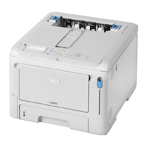
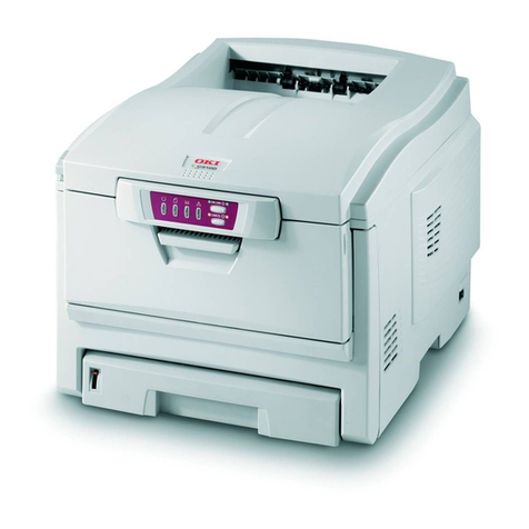
Oki C5650 Technical specifications

Oki Data CONFIDENTIAL
C5650/C6050/C6150/MPS6150c
Maintenance Manual
080409B

Copyright Information
Copyright © 2008by Oki Data. All Rights Reserved
Disclaimer
Every effort has been made to ensure that the information in this document is
complete, accurate, and up-to-date. The manufacturer assumes no responsibility
for the results of errors beyond its control. The manufacturer also cannot
guarantee that changes in software and equipment made by other manufacturers
and referred to in this guide will not affect the applicability of the information in it.
Mention of software products manufactured by other companies does not
necessarily constitute endorsement by the manufacturer.
While all reasonable efforts have been made to make this document as accurate
and helpful as possible, we make no warranty of any kind, expressed or implied,
as to the accuracy or completeness of the information contained herein.
The most up-to-date drivers and manuals are available from the web site:
http://www.okiprintingsolutions.com
Oki Data CONFIDENTIAL

43827101TH Rev.2 3 /
Oki Data CONFIDENTIAL
PREFACE
This manual explains the maintenance methods for the C5650/C6050/C6150. The manual has been
prepared for use by the maintenance personnel. For operating methods of the C5650/C6050/C6150,
refer to the corresponding user's manual.
Note!
• The contents of this manual are subject to changes without prior notice.
• Despitethatexhaustiveeffortsweremadeinpreparingthemanualtomakeitaccurate,itstillmay
containerrors.OkiDatawillnotholditselfliableforanydamagethatresultsorisclaimedtohave
resulted from repair, adjustment, or modification of the printer conducted by the user using this
manual.
• The parts employed in the printer are so delicate that they may be damaged if not treated
properly. Oki Data strongly recommends that the maintenance of the printer be undertaken by
Oki Data's registered maintenance personnel.
• Work after eliminating static electricity.

43827101TH Rev.2 4 /
Oki Data CONFIDENTIAL
CONTENTS
1. CONFIGURATION............................................................................................... 8
1.1 System configuration .............................................................................................................. 8
1.2 Printer configuration.............................................................................................................. 10
1.3 Composition of optional items............................................................................................... 12
1.4 Specifications........................................................................................................................ 13
1.5 Interface specifications ......................................................................................................... 17
1.5.1 Parallel interface specifications ............................................................................... 17
1.5.1.1 Parallel Interface Overview ..................................................................... 17
1.5.1.2 Parallel Interface Connector and Cable .................................................. 17
1.5.1.3 Parallel Interface Level ............................................................................ 17
1.5.1.4 Timing Chart ............................................................................................ 18
1.5.1.5 Parallel Interface Signal........................................................................... 19
1.5.2 USB interface specifications (C5650/C6050/C6150............................................... 20
1.5.2.1 Outline of USB interface .......................................................................... 20
1.5.2.2 USB interface connectors and cables ..................................................... 20
1.5.2.3 USB interface signals .............................................................................. 20
1.5.3 Network interface specifications (C5650/C6050/C6150) ........................................ 21
1.5.3.1 Outline of network interface..................................................................... 21
1.5.3.2 Network interface connectors and cables................................................ 22
1.5.3.3 Network interface signals ........................................................................ 22
2. EXPLANATION OF OPERATION ..................................................................... 23
2.1 Electrophotographic processing mechanism ........................................................................ 23
2.2 Printing process .................................................................................................................... 28
3. INSTALLATION................................................................................................. 38
3.1 Cautions, and do's and don'ts............................................................................................... 38
3.2 Unpacking method ................................................................................................................ 40
3.3 Printer Installation Instructions.............................................................................................. 41
3.4 Listing of component units and accessories ......................................................................... 42
3.5 Assembling method .............................................................................................................. 43
3.5.1 Assembly of printer main body ................................................................................ 43
3.5.2 Connection of power cable ...................................................................................... 49
3.5.3 Installation of optional items .................................................................................... 52
3.5.4 Confirmation of recognition of optional items........................................................... 61
3.6 Menu Map print ..................................................................................................................... 62
3.7 Connection methods ............................................................................................................. 64
3.8 Confirmation of paper used by the user................................................................................ 67
4. REPLACEMENT OF PARTS............................................................................. 68
4.1 Precautions on the replacement of parts .............................................................................. 68
4.2 Part replacement methods.................................................................................................... 70
4.2.1 Left side cover ......................................................................................................... 70
4.2.3 Face-Up Tray.......................................................................................................... 72

43827101TH Rev.2 5 /
Oki Data CONFIDENTIAL
4.2.4 Rear cover ...............................................................................................................73
4.2.5 LED Assy/LED Assy springs.................................................................................... 74
4.2.6 CU PCB ................................................................................................................. 75
4.2.7 Print engine controller PCB .................................................................................... 77
4.2.8 Top cover assembly ............................................................................................... 79
4.2.9 Top cover................................................................................................................ 80
4.2.10 Controller Panel Assy ............................................................................................. 81
4.2.11 Operator panel PCB/ Top Cover Handle ............................................................... 82
4.2.12 Low-Voltage Power Supply / Low-Voltage Fan /
Hopping Motor / Fuser Motor.................................................................................. 83
4.2.13 Guide Eject Assy / Color Register Assy / Junction PCB........................................ 84
4.2.14 Fan (Fuser)/ Belt Motor / High-Voltage Power Supply Board /
Cover-Open Switch ............................................................................................... 86
4.2.15 MPT Assy .............................................................................................................. 87
4.2.16 Feeder Unit / Front sensor PCB/ MPT Hopping Roller /
Frame Assy Separator / Cover Front...................................................................... 88
4.2.17 Toner sensor PCB Lift-Up Motor/Solenoid/Paper-End Sensor............................... 89
4.2.18 Feed Roller ............................................................................................................. 91
4.2.19 Shaft Eject Assy(FU) / Shaft Eject Assy(FD) / Eject Sensor .................................. 92
4.2.20 Fuser Unit ............................................................................................................... 93
4.2.21 Belt Unit .................................................................................................................. 94
4.3 Lubricating points.................................................................................................................. 95
5. MAINTENANCE MENUS................................................................................. 113
5.1 System maintenance menu (For maintenance personnel) ................................................. 113
5.2 Maintenance utility .............................................................................................................. 116
5.3 Functions of user's maintenance menu .............................................................................. 120
5.3.1 Maintenance menu (For end users)....................................................................... 120
5.3.2 Self-diagnostic mode ............................................................................................. 122
5.3.2.1 Operator panel....................................................................................... 122
5.3.2.2 Normal self-diagnostic mode (Level 1) .................................................. 125
5.3.2.2.1 Activation method for self-diagnostic mode (Level 1) ......... 126
5.3.2.2.2 Deactivation of self-diagnostic mode .................................. 126
5.3.2.3 Switch scan test..................................................................................... 126
5.3.2.4 Motor clutch test .................................................................................... 129
5.3.2.5 Test print................................................................................................ 131
5.3.2.6 Color registration adjustment test.......................................................... 136
5.3.2.7 Print density adjustment test ................................................................. 137
5.3.2.8 Indication of consumable part counters................................................. 139
5.3.2.9 Indication of printed page counters ....................................................... 140
5.3.2.10 Factory/Shipping switching.................................................................. 140
5.3.2.11 Setup of self-diagnostic function.......................................................... 141
5.3.2.12 Indication of LED head serial number ................................................. 142
5.3.2.13 Details of panel indications.................................................................. 143

43827101TH Rev.2 6 /
Oki Data CONFIDENTIAL
5.3.3 Various types of print on the individual printer equipped with controller................ 154
5.3.4 Functions of keys when depressed at power-on ................................................... 154
5.4 Setup after replacement of parts......................................................................................... 155
5.4.1 Precautions on the replacement of engine control PCB....................................... 155
5.4.2 Setup of EEPROM after replacement of CU PCB ................................................ 158
5.4.2.1 Replacement of EEPROM after replacement of PDL CU PCB
(C6150/C6050/C5950/C5750) ............................................................... 158
5.4.2.2 Setup of CU Serial Number ................................................................... 158
5.4.3 Setup of destination.............................................................................................. 159
5.5 About the manual setup of Print density adjustment........................................................... 160
6. PERIODICAL MAINTENANCE ....................................................................... 161
6.1 Recommended replacement parts...................................................................................... 161
6.2 Cleaning.............................................................................................................................. 161
6.3 Cleaning of LED lens array ................................................................................................. 161
6.4 Cleaning of pickup rollers.................................................................................................... 163
6.5 Internal cleaning of printer .................................................................................................. 164
Cleaning the interior of the printer....................................................................................... 164
7. TROUBLESHOOTING PROCEDURES .......................................................... 166
7.1 Precautions prior to repair................................................................................................... 166
7.2 Items to be checked prior to taking action on abnormal images......................................... 166
7.3 Precautions when taking action on abnormal images......................................................... 166
7.4 Preparations for troubleshooting......................................................................................... 166
7.5 Troubleshooting method ..................................................................................................... 166
7.5.1 LCD Message List ................................................................................................ 167
7.5.2 Preparing for troubleshooting ................................................................................ 183
7.5.2.(1) LCD Display Malfunction ............................................................................. 185
7.5.2.(2) Irregular Operation of the device after turning on the power....................... 188
7.5.2.(3) Paper Feed Jam(Error 391:1st Tray)........................................................... 198
7.5.2.(4) Paper Feed Jam (Error 390:Multi-purpose Tray)......................................... 200
7.5.2.(5) Paper Path Jam(Error 381) ......................................................................... 202
7.5.2.(6) Paper Exit Jam(Error 382)........................................................................... 207
7.5.2.(7) Duplex Print Jam(Error 370,371,372,373,383)............................................ 210
7.5.2.(8) Paper Size Error (Error 400) ....................................................................... 212
7.5.2.(9) ID Unit Up-Down Error(Service Call 140-143)............................................. 213
7.5.2.(10) Fuser Unit Error(Error 170-177) .................................................................. 215
7.5.2.(11) Motor Fan Error(Error 120,127,051)............................................................ 216
7.5.2.(12) Print Speed is Slow (Low Performance)...................................................... 217
7.5.2.(13) Option unit is not recognized....................................................................... 217
7.5.2.(14) LED head is not recognized(Error 131,132,133,134).................................. 218
7.5.2.(15) Toner cartridge is not recognized(Error 540,541,542,543).......................... 219
7.5.2.(16) Fuse Cutout Error (Error 150-155) .............................................................. 220
7.5.2.(17) Dew Condensation Errors (Error 123)......................................................... 221
7.5.3 Image Problem Troubleshooting .......................................................................... 222
7.5.3.(1) Color is totally pale (Fig.7.2 A ).................................................................... 223
7.5.3.(2) Background is dirty (Fig.7.2 B ) ................................................................... 224
43827101TH Rev.2 7 /
Oki Data CONFIDENTIAL
7.5.3.(3) Blank Print (Fig.7.2 C ) ................................................................................ 225
7.5.3.(4) Vertical lines are printed .............................................................................. 226
7.5.3.(5) Cyclic Print Trouble (Refer to Fig.7.2 E )..................................................... 227
7.5.3.(6) Color registration is wide. ............................................................................ 228
7.5.3.(7) Solid Black Print .......................................................................................... 229
7.5.4 Actions after forced initialization of HDD/Flash .................................................... 230
7.5.5 Network Troubleshooting...................................................................................... 231
7.6 Check of fuses .................................................................................................................... 232
8. CONNECTION DIAGRAMS ............................................................................ 233
8.1 Check of resistance values ................................................................................................. 233
8.2 Component layout............................................................................................................... 237
8.3 F/W version......................................................................................................................... 249
8.3.1 ROM management number .................................................................................. 249
8.3.2 F/W version display in PDL CU PCB.................................................................... 249

43827101TH Rev.2 8 /
Oki Data CONFIDENTIAL
1. CONFIGURATION
1.1 System configuration
C6150/C6050
Figure 1-1-1 represents the system configuration of the printer.
Figure 1-1-1
RFID
Centronics
EEP
ROM
K LED HEAD
Y LED HEAD
M LED HEAD
C LED HEAD
Operator panel PCB
Toner sensor PCB
High-voltage PCB
Low-voltage PCB
ARMORED CPU
Paperfeed
solenoid
Front sensor PCB
DUPLEX PCB 2nd TRAYPCB
IN1 IN2 WR
M
ID M
HOP M
IDUP
M
FUSER
M
BELT
1st
P.E
sensor
Belt unit
PUPCB
Junction PCB
Fuser
Unit
Inlet
EXIT
sensor
Density
sensor
Color
registration
PCB right
Belt unit
fuse-cut
Fuser fuse-cut,
UP&LOW
thermistor/frame
thermistor
Belt unit
fuse-cut,
EXIT
Color drift, density,
thermistor signal
20MHz
FLASH
8Mbit
Environmental
temperature & humidity
signals,High-voltage I/F,
fan control, cover-open
FAN heater control,
others
5V,24V, 0VL,0VP
EEPROM
K-ID Y-ID M-ID C-ID
Low-
voltage
FAN
AC-SW
Fuser
fan
Belt
thermi-
stor
ID UP/
DOWN
Cover-
open
sensor
K toner
sensor Y toner
sensor M toner
sensor C toner
sensor ID
fuse-cut
CC1
ASIC
CIF2
ASIC
HDD
LAN USB
CUPCB
Flash
ROM
Option
RAM
LEISUS
command I/F
Environment
sensor
DCON I/F LSYNC
CPU
Color
registration
PCB left

43827101TH Rev.2 9 /
Oki Data CONFIDENTIAL
C5650
Figure 1-1-2 represents the system configuration of the printer.
Figure 1-1-2
Color
registration
PCB right
Color
registration
PCB left
K LED HEAD
Y LED HEAD
M LED HEAD
C LED HEAD
Front sensor PCB
DUPLEX PCB 2nd TRAY PCB
IN1 IN2 WR
M
ID M
HOP M
IDUP
M
FUSER
M
BELT
LAN
NIC
Serial
Flash
ROM
DDR
SDRAM
USB
SPILYTAS2
Operator panel PCB
Toner sensor PCB
High-voltage PCB
Low-voltage PCB
ARMORED CPU
Belt unit
PU PCB
Junction PCB
Fuser Unit Inlet
EXIT
sensor
Density
sensor
Belt unit
fuse-cut
Fuser fuse-cut,
UP&LOW thermistor/frame
thermistor
Belt unit
fuse-cut,
EXIT
Color drift, density,
thermistor signal 20MHz
FLASH
8Mbit
FAN heater control,
others 5V,24V, 0VL,0VP
EEPROM
K-ID Y-ID M-ID C-ID
Low-
voltage
FAN AC-SW
Fuser
fan
Belt
thermi-
stor
ID UP/
DOWN
Cover-
open
sensor
K toner
sensor Y toner
sensor M toner
sensor C toner
sensor ID fuse-cut
Environment
sensor
Paperfeed
solenoid
1st
P.E
sensor
5V
25MHz
48MHz
CU PCB
LEISUS
Command I/F
RFID
Environmental
temperature & humidity
signals, High-voltage I/F,
fan control, cover-open

43827101TH Rev.2 10 /
Oki Data CONFIDENTIAL
1.2 Printer configuration
TheinternalpartoftheC6050/C6150printeriscomposedofthefollowingsections:
• Electrophotographic processing section
• Paper paths
• Control sections (CU sect./PU sect.)
• Operator panel
• Power supply sections (High-voltage sect./low-voltage sect.)
Figure 1-2-1 represents the configuration of the printer.
Figure 1-2-1
Air flow

43827101TH Rev.2 11 /
Oki Data CONFIDENTIAL
The internal part of the C5650 printer is composed of the following sections:
•Electrophotographic processing section
•Paper paths
•Control sections (CU sect./PU sect.)
•Operator panel
•Power supply sections (High-volatge sect./low-voltage sect.)
Figure 1-2-2 represents the configuration of the printer.
Figure 1-2-2
Air flow

43827101TH Rev.2 12 /
Oki Data CONFIDENTIAL
1.3 Composition of optional items
The following optional items are available for the printer:
(1) Second tray (C5650/C6050/C6150)
(2) Duplex Unit (C5650/C6050/C6150)
(3) Expansion Memory (C6050/C6150) 256 MB / 512 MB
For long printing, it is recommended to
add an expansion memory.
* Not compatible with the expansion
memories for C5650.
(4) Expansion Memory (C5650) 64 MB / 256 MB
* Not compatible with the expansion
memories for C6050/C6150.
(5) Hard disk (C6050/C6150)

43827101TH Rev.2 13 /
Oki Data CONFIDENTIAL
1.4 Specifications
Division Item C5850 C5650 C6150 C5950 C6050 C5750
32/26ppm 32/22ppm 32/26ppm 32/26ppm 26/22ppm 32/22ppm
External
dimensions
Width 435mm
Depth With
duplex
621mm
Without
duplex
563.5mm
Height 340mm
Mass With
duplex
Approx.29kg
Without
duplex
Approx.26kg
Print width Print width A4
Engine speed
(A4)
Monochrome 32ppm 32ppm
(Default:26ppm)
32ppm 32ppm
(Default:26ppm)
Color 26ppm 22ppm 26ppm 22ppm
OHP Color 9ppm*1 9ppm*1 9ppm*1 9ppm*1
OHP color/ mono-
chrome
10ppm 10ppm 10ppm 10ppm
First print
time(A4)
Monochrome 8sec 8sec
(Default:10sec)
8sec 8sec
(Default:10sec)
Color 9sec 11sec 9sec 11sec
Warm-up time 45sec
Low-noise mode Not applicable
Resolution LED head 600dpi
Max. input resolution 600x1200dpi
Output resolution True 600x1200dpi
True 600x600dpi
True 600x1200dpi
True 600x600dpi
Gradation 600x600x4 level
Econo-mode Toner-saving by reducing lightness
CPU Core PowerPC405 PowerPC750CL
I-cache 16KB, 32KB
D-cache 16KB 32KB (Internal L2 : 256KB)
Clock 200MHz 500MHz
Bus width 32bit 64bit
RAM Resident 64 MB 256 MB
Option 64/256MB DIMM 256/512MB DIMM
ROM Program + font Total capacity: 8MB Total capacity: 64MB
Power con-
sumption
Power input (120V)110~127VAC , (230V)220~240VAC
Power-save mode 15W or less 17W or less
Idle 100W (Average)
Normal operation 490W
Peak 1200W
Operating
environment
(Temperature)
When operating 10¡C~32¡C, 17¡C~27¡C(Full-color print quality guarantee temperature)
When not operating 0¡C~43¡C, Power off
When stored
(For max. 1 yr.)
-10¡C~43¡C, With drum and toner
When transported
(For max. 1 mo.)
-29¡C~50¡C, With drum, but no toner
When transported
(For max. 1 mo.)
-29¡C~50¡C, With drum and toner
20%~80%, 50%~70%(Full-color print quality guarantee humidity)
Operating
environment
(Humidity)
When operating Max. wet-bulb temp. : 25¡C
When not operating 10%~90%, Max. wet-bulb temp. : 26.8¡C, with power off
When stored 10%~90%, Max. wet-bulb temp. : 35¡C
When transported 10%~90%, Max. wet-bulb temp. : 40¡C

43827101TH Rev.2 14 /
Oki Data CONFIDENTIAL
Division Item C5850 C5650 C6150 C5950 C6050 C5750
32/26ppm 32/22ppm 32/26ppm 32/26ppm 26/22ppm 32/22ppm
Service life Printer life 420,000 pages, 5 years
Print duty
(M=L/12, A=L/12/5) Max. 50,000 pages / mo.
Average 4,000 pages / mo.
MTBF (2.3% duty) Not applicable
MPBF 40,000 pages
MTTR 20 minutes
Toner life
(5% Duty) Starter
toner Approx. 1500
pages (Black)
Approx. 1500
pages (Color)
Approx. 1500
pages (Black)
Approx. 1500
pages (Color)
Approx. 2000
pages (Black)
Approx. 2000
pages (Color)
Approx. 1500
pages (Black)
Approx. 1500
pages (Color)
Approx. 2000
pages (Black)
Approx. 2000
pages (Color)
Approx. 1500
pages (Black)
Approx. 1500
pages (Color)
Standard Approx. 8000
pages (Black)
Approx. 6000
pages (Color)
Approx. 8000
pages (Black)
Approx. 2000
pages (Color)
Approx. 8000
pages (Black)
Approx. 6000
pages (Color)
Approx. 8000
pages (Black)
Approx. 6000
pages (Color)
Approx. 5000
pages (Black)
Approx. 4000
pages (Color)
Approx. 8000
pages (Black)
Approx. 2000
pages (Color)
With 1st
new drum Approx. 7200
pages (Black)
Approx. 5200
pages (Color)
Approx. 7200
pages (Black)
Approx. 1200
pages (Color)
Approx. 7200
pages (Black)
Approx. 5200
pages (Color)
Approx. 7200
pages (Black)
Approx. 5200
pages (Color)
Approx. 4200
pages (Black)
Approx. 3200
pages (Color)
Approx. 7200
pages (Black)
Approx. 1200
pages (Color)
Image drum life Approx.20,000 pages (With 3 pages / job) Approx.12,000 pages (With 1 page / job)
Approx.27,000 pages (When printed continuously) Drum counter automatically reset
Transfer belt life 60,000 pages (A4 size, with 3 pages / job), counter automatically reset
Fuser unit life 60,000 pages (A4 size), counter automatically reset
Operation
noise In operation
(ISO7779Front)
In one-side print
55.6dBA
On standby
(ISO7779Front) 37dBA
Power-save mode Background level
Paper
handling Paper capacity
(1st tray) Legal/universal cassette:300 sheets (70kg)
Paper capacity
(2nd tray) Legal/universal cassette (Optional):530 sheets (70kg)
Paper capacity
(Manual/auto) Standard multi-purpose tray:50 OHP sheets
or 100 sheets of paper (70kg) or 10 envelopes
Delivery 250 sheets (70kg) face-down/100 sheets (70kg)face-up in tray
Duplex Standard / optional
(Depending on specification)
Paper size Legal / universal or
A4-size cassette /
universal cassette
1st cassette: Legal13/13.5/14, letter, executive, A4, A5, B5, A6
2nd cassette: Legal13/13.5/14, letter, executive, A4, A5, B5
Reply-paid postcard (Max. 176gsm) (Multi-purpose tray)
Automatic front feeder
or manual feeder Legal13/13.5/14, letter, executive, A4, A5, B5, A6, C5, DL, Com-9,Com-10, Monarch, custom size,
banners up tp 1220mm (When paper length exceeds 356, its width shall be from 210 to 215.9.)
Two-sided Legal13/13.5/14, letter, executive, A4, A5 Custom size (Within permissible size and weight)
Min. paper
size 1st tray 105x148mm:A6/(Models for Japan [100x148: Postcard size])
2nd tray 148x210mm:A5
Manual & auto (MPT) 76.2x127 : Index Card
Two-sided 148x210mm:A5

43827101TH Rev.2 15 /
Oki Data CONFIDENTIAL
Division Item C5850 C5650 C6150 C5950 C6050 C5750
32/26ppm 32/22ppm 32/26ppm 32/26ppm 26/22ppm 32/22ppm
Paper
thickness
1st tray 64~120gsm
2nd tray 64~176gsm
Manual &
auto (MPT)
64-203gsm OHP sheets available
Two-sided 64~105gsm
Operator
panel
LCD 16 characters in 2 line (Roman alphabet/Japanese kana)
No paper size indicated
LED (Color) Two (Green x1, dark amber x1)
Switch Six
Status
switch/
sensor
Paper out Provided
Paper low Not provided
Toner low Provided (Y,M,C,K)
Cover open Provided
Fuser unit temp. Provided
Paper size Not provided
Stacker full Not provided
Standard
( On PCB)
Hi-Speed USB
Ethernet
Additional
Function
Not available Bidirectional parallel I/F conforming
to IEEE std1284-1994
Input/output
switch
Automatic
Emulation Standard Hiper-C PCL (PCL5c, HP-GL) / PCL XL2.1
SIDM (IBM-PPR, EPSON-FX)
PostScript3 (Clone) PDF Direct Print1.5
Emulation switch Not provided Automatic
Font Bit-map type face Not available Agfa 1(Line printer)
Scalable 1 type
face
Not available Agfa micro-type 86
Scalable 2 type
face
Not available
Scalable 3 type
face
Not available Agfa micro-type 136
Rasterizer Not available Agfa UFST 4.0 (PCL)
Bar code Not available USPS
OCR Not available OCR-A,B
Japanese PCL font Not available
Japanese PS font Not available

43827101TH Rev.2 16 /
Oki Data CONFIDENTIAL
Note!
Expansion memories for C5650 and those for C6050/C6150
are not compatible with each other.
Division Item C5850 C5650 C6150 C5950 C6050 C5750
32/26ppm 32/22ppm 32/26ppm 32/26ppm 26/22ppm 32/22ppm
Optional Item
(Detacchable)
RAM set 64, 256 MB 256, 512 MB
Tray mechanism 2nd tray mechanism
Cassette Legal/universal (530 sheets)
Two-sided print unit Available
Othes Not applicable 2.5" IDE HDD User- installable
Factory settings Japan GDI Model PCL+PS model
Others USB-IF logo Available
Windows logo Available
Operation with UPS Operation with UPS (Uninterruptible power supply) is not guaranteed. Do not use UPS

43827101TH Rev.2 17 /
Oki Data CONFIDENTIAL
1.5 Interface specifications
1.5.1 Parallel interface specifications
1.5.1.1 Parallel Interface Overview
1.5.1.2 Parallel Interface Connector and Cable
(1) Connector
Printer: 36pConnector (Female)
57LE-40360-12 (D56) (DDK Ltd.) equivalent product
Cable: 36pConnector (Male)
57FE-30360-20N (D8) (DDK Ltd.) equivalent product
Item Details
Corresponding mode Comatible mode, nibble mode, ECP mode
Compatible: 8, Nibble: 4, ECP: 9 bitData bit length
(2)Cable
Use a cable shorter than 1.8m.
(Use a cable with a shielded twisted-pair wire for to prevent noise interference.)
1.5.1.3 Parallel Interface Level
Low Level: 0.0V to +0.8V
High Level: +2.4V to +5.0V
118
1936
Pin arrangement from interface cable side

43827101TH Rev.2 18 /
Oki Data CONFIDENTIAL
1.5.1.4 Timing Chart
■Compatible Mode
a) Data Reception Timing
b) Online/Online SW for Offline Switching Timing
c) Offline/Online SW for Online Switching Timing
d) nlnit Timing (Default Invalid)
PARALLEL DATA
(DATA BITs 1 to 8)
nStrobe
nAck
BUSY
0.5 µs min. 0.5 µs min.
0.5 µs min.
0.5 µs max.
0.5 µs min.
0 min. 0 min.
0.5 µs to 3 µs0 min.
ON-LINE SW
BUSY
100 ms max.
SELECT
SELECT
ACKNOWLEDGE
ON-LINE SW
BUSY
INPUT. PRIME
SELECT
ACKNOWLEDGE
BUSY
50 µs min.
* It is based on a menu setup.
5µs max.

43827101TH Rev.2 19 /
Oki Data CONFIDENTIAL
1.5.1.5 Parallel Interface Signal
The name of the interface signal and pin number is indicated in Table 9-1.
Table 1-1 Signals
Nibble mode signal names are indicated in the ( ).
Only indicates the Compatible Mode functions.
This printer supports the IEEE 1284-1994 Nibble Mode standardized by the Institute of Electric
and Electronic Engineers (IEEE). Note that use of PCs and cables that do not comply with
this standard may result in unforeseeable operations.
Pin No.
1
2
3
4
5
6
7
8
9
10
11
12
13
14
15
16
17
18
19 to 30
31
32
33
34
35
36
Direction
TO PRINTER
TO PRINTER
FROM PRINTER
FROM PRINTER
FROM PRINTER
FROM PRINTER
TO PRINTER
—
—
—
FROM PRINTER
—
TO PRINTER
FROM PRINTER
—
—
FROM PRINTER
TO PRINTER
Signal Name
nStrobe
(HostClk)
DATA 1
DATA 2
DATA 3
DATA 4
DATA 5
DATA 6
DATA 7
DATA 8
nAck (PtrClk)
Busy (PtrBusy)
PError (AckDataReq)
Select (Xflag)
nAutoFd (HostBusy)
Unused
GND
FG
+5V
GND
nInit (nInit)
nFault (nDataAvail)
GND
Unused
HILEVEL
nSelectIn
(IEEE1284 active)
Function
Pulse to read data.
Data is read with the latter wire.
8bit parallel data.
High Level: "1"
Low Level: "0"
Signal indicating completion of incoming data.
Indicates whether the printer state can accept data
or not.
Data cannot be accepted during High Level.
Paper error takes place during High Level.
Always High Level when the parallel interface is
active.
Used for two-way communications.
Unconnected
Ground for signal.
Ground for chassis.
Provides +5V. Cannot supply power to an external
device.
Ground for signal.
Printer is initialized during Low Level.
When printer is alarming the printer goes to Low
Level state.
The ground for signals
Un-connecting.
It is pulled up by +5V through 3.3k .
Used for two-way communications. Always in Low
Level in the compatible mode.
Note

43827101TH Rev.2 20 /
Oki Data CONFIDENTIAL
1.5.2 USB interface specifications (C5650/C6050/C6150)
1.5.2.1 Outline of USB interface
(1) Basic specifications
USB (Hi-Speed USB supported)
(2) Transmission mode
Full speed (Max. 12Mbps ±0.25%)
High speed (Max.480Mbps ±0.05%)
(3) Power control
Self power device
1.5.2.2 USB interface connectors and cables
(1) Connector
•Printer side: B-receptacle (Female)
Upstream port
Product equivalent to UBR24-4K5C00 (Made by ACON)
2
34
1
Connector pin assignment
•Cable side: B-plug (Male)
(2) Cables
Cablelength: Specification: USB2.0 typecablesfive meters long orshorter. Cables two meterslong
or shorter are recommended. (Shielded cable lines shall be used.)
1.5.2.3 USB interface signals
1
2
3
4
Shell
Signal name
Vbus
D-
D+
GND
Shield
Function
Power supply (+5V)
For data transfer
For data transfer
Signal ground
Other manuals for C5650
2
This manual suits for next models
3
Table of contents
Other Oki Printer manuals

Oki
Oki Pacemark PM4410 Parts list manual

Oki
Oki LP470w User manual

Oki
Oki OKIPAGE 8c Plus User manual

Oki
Oki MAC TECHNICAL REFERANCE C7350 User manual

Oki
Oki PAGE 6w Specification sheet

Oki
Oki C3600n Specification sheet

Oki
Oki ES1624n MFP Use and care manual

Oki
Oki Pacemark PM4410 Training manual

Oki
Oki OKIPOS 426S User manual

Oki
Oki LED Printer User manual