8
11
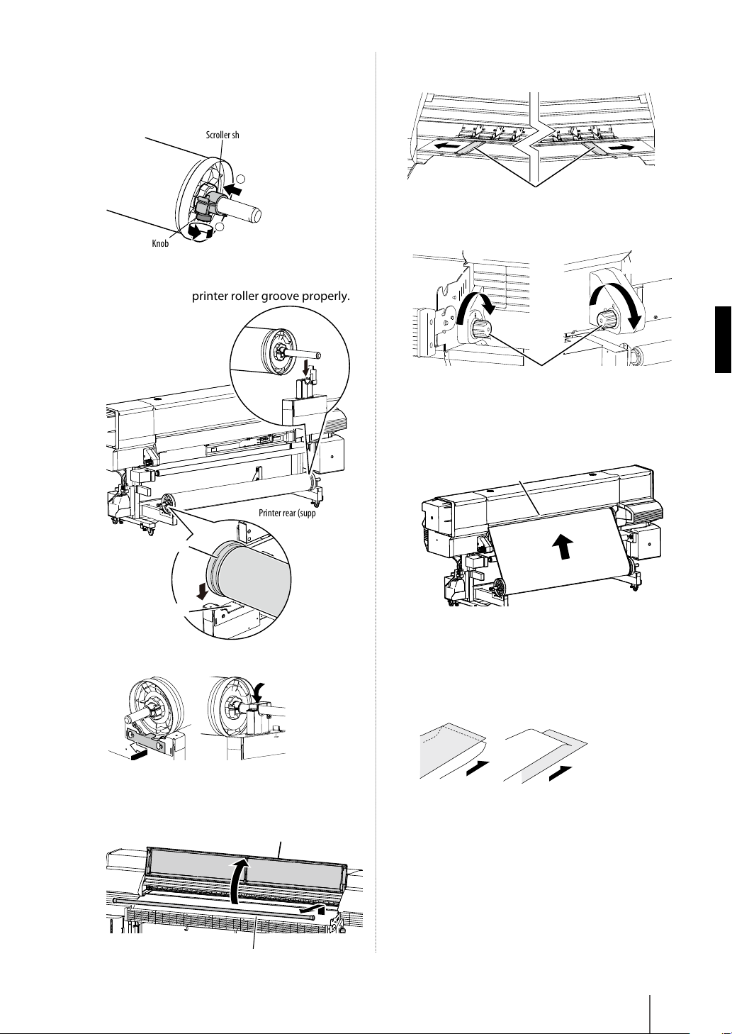
Feed the media until the media end almost
reaches the oor.
In this state, smooth out the media toward the both
sides on the platen to make the media center tense.
Platen
Note
-If the media is set with a distortion or wrinkles, this may cause a
media jam or skew.
12
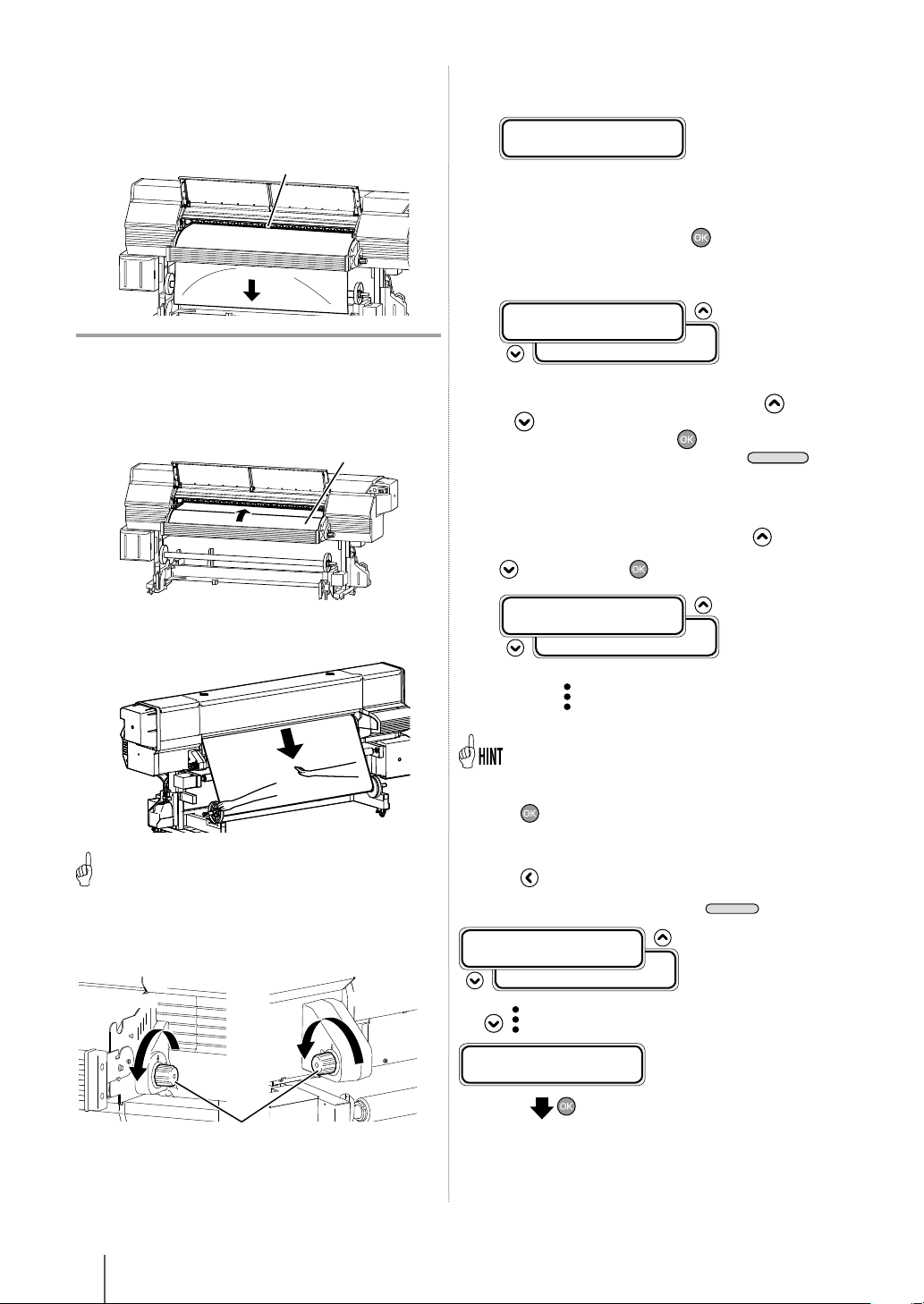
Feed back the media to the top of the front
paper guide. Front paper guide
Feed back the media while pressing the center of
the media gently at the supply side.
NOTICE
-Step 12 is important to set the media properly.
13
Takeup side Supply side
or
Pressure control knobs
Rotate the pressure control knob in the arrow
direction to lower the pressure roller.
14
Set the media edge guards and close the front
cover.
CHECK EDGE GUARD
*OK?
Check that the media edge guards are not under the
media or thick media is not caught by inserting it
forcibly. After conrming visually that the media edge
guards are properly set, press the key.
15
Select roll media or cut-sheet media.
ROLL/SHEET:SHEET
SELECT MEDIA
ROLL/SHEET:ROLL
Either [roll] or [sheet] can be selected with the key
or key.
Here, select [roll] and press the key.
(To return to the media selection, press the
key.)
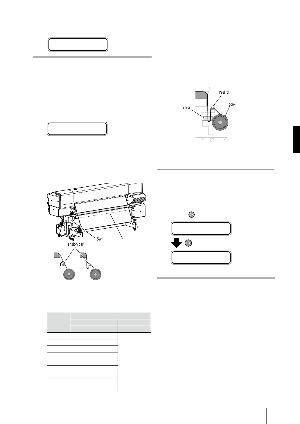
16
Select the type of media.
Select the registered type of media with the and
keys and press the key.
MEDIA:TYPE02
SELECT MEDIA
MEDIA:TYPE02
To register new media
[NEW MEDIA ENTRY] is displayed at the end of the registered
media.
Press the key to enter MEDIA REG MENU.
The media registration procedure is the same as the registration
from the registration menu.
Press the key to return from the media registration menu to
the media type selection menu.
To return to the value before input, press the
key.
MEDIA:TYPE02
SELECT MEDIA
MEDIA:TYPE02
(The registered media is displayed.)
SELECT MEDIA
NEW MEDIA ENTRY
(Enter the media registration menu.)