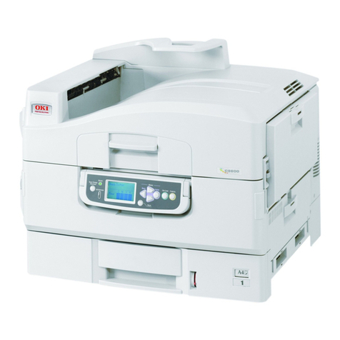
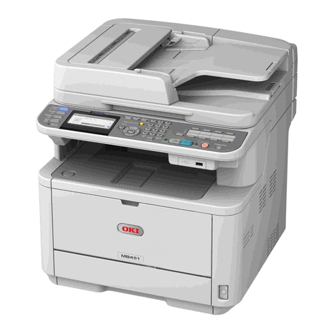
Oki MC362w User manual

MC362w / MC562w
MPS2731mc
Maintenance Manual
062813A

Copyright Information
Copyright © 2013 by Oki Data. All Rights Reserved
Disclaimer
Every effort has been made to ensure that the information in this document is complete, accurate, and up-to-
date. The manufacturer assumes no responsibility for the results of errors beyond its control. The
manufacturer also cannot guarantee that changes in software and equipment made by other manufacturers and
referred to in this guide will not affect the applicability of the information in it. Mention of software products
manufactured by other companies does not necessarily constitute endorsement by the manufacturer.
While all reasonable efforts have been made to make this document as accurate and helpful as possible, we
make no warranty of any kind, expressed or implied, as to the accuracy or completeness of the information
contained herein.
The most up-to-date drivers and manuals are available from the web site:
http://www.okiprintingsolutions.com

44952001TH Rev.2 ii
Oki Data CONFIDENTIAL
Document Revision History
Rev.
No. Date
Changed items
Person in charge
No. Page Description of change
1 2012-04-26 Issue NME12 H. Ueda
2 2013-02-15 Addition of Wireless-LAN
spec. etc
P1E12 H. Enomoto
Rev.
No. Date
Changed items
Person in charge
No. Page Description of change
Document Revision History

44952001TH Rev.2 iii
Oki Data CONFIDENTIAL
This manual explains the maintenance methods of MC352/MC362/MC562 series.
This manual is prepared for the maintenance person. In regard to the handling methods of
MC352/MC362/MC562 series, please refer to the User’s Manual.
Note! • Contentsofthismanualissubjecttochangewithoutnotice.
• While all reasonable efforts have been made to make this document
as accurate and helpful as possible, we make no warranty of any kind,
expressed or implied, as to the accuracy of the information contained
herein. Oki Data assumes no responsibility to the damages caused or
claimedtohavebeencausedbytheuserasaresultofrepair,adjustment
and/or change using this manual.
• Parts of this product are delicate and can be damaged unless properly
handled. We strongly recommend the user to maintain the product at the
hand of the registered maintenance person of our company
• Beforestartingthemaintenancework,pleaseneutralizethestaticelectricity.
Refer to the following table for a classification and function of equipment.
wireless LAN Low class High class
without FAX with FAX
Entry Desk Top Not apply MC332 MC342 -
Apply - MC342dw -
Standard Not apply MC352 MC362 MC562
Apply - MC362w MC562dw
MC562w
MPS model Not apply ES3452MFP - ES5462MFP
Apply - - ES5462dw MFP
MPS2731mc
PREFACE
PREFACE
Refer to the following table for the board classification and the board name.
Classification board name
CU/PU board : CLQ / CLW
(CLWistheboardcommunalizedversion,and
can connected wireless LAN module. )
High voltage power supply board : ORZ
Toner sensor board : ZHJ
SU board : MHE / MHH
(MHHisthedestinationcommunalizedversion.)
Ope board : OPM
ADF board : MHD
Option tray board : GOG
Risk of explosion if battery is replaced by an incorrect type.
Battery of the printer need not to be replaced. Do not touch the
battery.
Replace the whole board to replace the SU board.
In the case of replacing batteries at board repairs, replace with the
specified type ones.
Installation of another type batteries may result in
explosion.
Caution for used batteries are as follows; do not recharge, force open,
heat or dispose of in fire.

44952001TH Rev.2 iv
Oki Data CONFIDENTIAL
CONTENTS
CONTENTS
1. CONFIGURATION..................................................................1-1
1.1 System configuration ......................................................................................1-2
1.2 Structure of MFP .............................................................................................1-4
1.3 Offer of Options ...............................................................................................1-6
1.4 Specifications ..................................................................................................1-7
1.5 Interface specifications .................................................................................1-27
1.5.1 USB Interface Specification......................................................................1-27
1.5.1.1 Outline of USB Interface...................................................................1-27
1.5.1.2 USB Interface Connector and Cable ................................................1-27
1.5.1.3 USB Interface Signal ........................................................................1-27
1.5.2 Network Interface Specification................................................................1-28
1.5.2.1 Outline of Network Interface.............................................................1-28
1.5.2.2 Network Interface Connector and Cable ..........................................1-28
1.5.2.3 Network Interface Signal ..................................................................1-28
1.5.3 Telephone Line Interface Specification
(MC342/MC362/MC562/MC342dw/MC362w/MC562dw).........................1-29
1.5.3.1 Outline of telephone Line Interface ..................................................1-29
1.5.3.2 Telephone Line Interface Connector and Cable ...............................1-29
1.5.3.3 Telephone Line Interface signal........................................................1-29
1.5.4 USB Host Interface...................................................................................1-29
1.5.4.1 Outline of USB Host Interface ..........................................................1-29
1.5.4.2 USB Host Interface Connector .........................................................1-29
1.5.4.3 USB Host Interface Signal................................................................1-29
1.5.5 Wireless LAN Interface (MC342w/MC352w)............................................1-30
2. DESCRIPTION OF OPERATION...........................................2-1
2.1 Electrophotographic process mechanism .......................................................2-2
2.2 Printing process ...............................................................................................2-6
2.3 Image Scanning process ...............................................................................2-18
2.3.1 Structure and process of RADF ...............................................................2-18
2.3.1.1 Cross-section view ...........................................................................2-18
2.3.1.2 Electrical configuration .....................................................................2-18
2.3.1.3 Fundamental operations...................................................................2-19
2.3.1.4 Document detection .........................................................................2-22
2.3.1.5 Jam detection ...................................................................................2-23
2.3.2 Document table structure .........................................................................2-23
2.3.2.1 Overview ..........................................................................................2-23
2.3.2.2 Exposure block.................................................................................2-24
2.3.2.3 Carraige-Assy drive mechanism ......................................................2-24
3. MFP INSTALLATION ..............................................................3-1
3.1 Precautions and Prohibition.............................................................................3-2
3.2 MFP Unpacking Procedure .............................................................................3-3
3.3 MFP Installation Instructions ...........................................................................3-4
3.4 Packed Units and Attachments .......................................................................3-5
3.5 Assembly Procedure .......................................................................................3-6
3.5.1 MFP Main Body .........................................................................................3-6
3.5.2 Power Cable Connection..........................................................................3-13
3.5.3 Installation of Optional Components ........................................................3-15
3.5.3.1 Second Tray Unit ..............................................................................3-15
3.5.3.2 Extension Memory Installation .........................................................3-18
3.5.3.3 16GB SD Memory card (MC562/MC562dw)....................................3-16
3.6 Configuration Page Print................................................................................3-22
3.7 Network Information Print ..............................................................................3-23
3.8 Connection Procedures .................................................................................3-24
3.9 Checking of User Paper .................................................................................3-28

44952001TH Rev.2 v
Oki Data CONFIDENTIAL CONTENTS
4. REPLACEMENT OF PARTS..................................................4-1
4.1 Notes on replacement of parts.........................................................................4-2
4.2 Part replacement procedure ............................................................................4-4
4.2.1 Belt unit ......................................................................................................4-4
4.2.2 Fuser unit ...................................................................................................4-5
4.2.3 Left side cover............................................................................................4-5
4.2.4 Right side cover..........................................................................................4-6
4.2.5 CU/PU board and low-voltage power supply..............................................4-7
4.2.6 Front cover ................................................................................................4-9
4.2.7 Scanner unit .............................................................................................4-11
4.2.7.1 Tray-assy-document / Cover-ADF-R-assy........................................4-12
4.2.7.2 ADF-unit ...........................................................................................4-13
4.2.7.3 Sheet-document / Paper-weight-assy / Spring-PW-ADF..................4-14
4.2.7.4 Hinge-assy-L / Hinge-assy-R ...........................................................4-15
4.2.7.5 Cover-ADF-F / Guide-assy-exit-sub / ADF-assy / ADF board ..........4-16
4.2.7.6 Cover-assy-top-ADF / Guide-assy / Roller / Motor / Clutch /
Solenoid ........................................................................................4-18
4.2.7.7 Guide-A-sub / Frame-assy-separator / Spring-separator /
Rubber-friction.................................................................................4-19
4.2.7.8 Cable (ADF-Rev SNS)......................................................................4-19
4.2.7.9 Cable (ADF-Reg SNS) .....................................................................4-20
4.2.7.10 Frame-assy-OP ................................................................................4-20
4.2.7.11 Frame-OP-panel / OPE board (MC562/MC562dw)..........................4-21
4.2.7.12 Frame-OP-panel / OPE board
(MC342/MC362/MC342dw/MC362w) ..............................................4-22
4.2.7.13 Frame-OP-panel / OPE board (MC332/MC352) ..............................4-23
4.2.7.14 LCD-assy..........................................................................................4-24
4.2.7.15 Frame-assy-FB.................................................................................4-25
4.2.7.16 How to remove Battery (SU Board)..................................................4-27
4.2.7.17 Frame-assy-hopping-ADF ................................................................4-28
4.2.7.18 Setting of SW1 and SW2 on MHH board (SU Board) ......................4-29
4.2.8 Face-up tray .............................................................................................4-30
4.2.9 Rear cover................................................................................................4-30
4.2.10 LED assembly. and LED assembly springs ..............................................4-31
4.2.11 Image drum fan and ZHJ board ...............................................................4-31
4.2.12 Top cover assembly..................................................................................4-32
4.2.13 Top cover and LED head cable assembly ................................................4-32
4.2.14 MPT assembly..........................................................................................4-33
4.2.15 Front fan, hopping motor, rear fan, image drum motor and
cover-open switch.....................................................................................4-34
4.2.16 High-voltage power supply board.............................................................4-35
4.2.17Guide-ejectionassembly,fuserconnectorassemblyand
color-registration assembly ......................................................................4-36
4.2.18 Frame-MPT assembly and feeder assembly............................................4-37
4.2.19 Side-L assembly, side-R assembly and base assembly...........................4-38
4.2.20 Feed rollers ..............................................................................................4-39
4.3 Locations to lubricate.....................................................................................4-40
4.3.1 ADF ..........................................................................................................4-41
4.3.2 Printer.......................................................................................................4-48
5. MAINTENANCE MENUS .......................................................5-1
5.1 Maintenance Menu ..........................................................................................5-2
5.2 Service Bit Menu..............................................................................................5-9
5.3 Maintenance Utility.........................................................................................5-10
5.3.1 Maintenance Utility...................................................................................5-10
5.3.2 Scanner Maintenance Tool .......................................................................5-12
5.4 Self-diagnostic mode .....................................................................................5-13
5.4.1 Operator Panel .........................................................................................5-13
5.4.2 Normal self-diagnostic mode (level 1)......................................................5-16
5.4.2.1 Entering self-diagnostic mode (level 1) ............................................5-16
5.4.2.2 Exiting self-diagnostic mode.............................................................5-16
5.4.3 Switch scan test .......................................................................................5-17
5.4.4 Motor and clutch test................................................................................5-19
5.4.5 Test printing..............................................................................................5-21
5.4.6 Colorregistrationadjustmenttest.............................................................5-25
44952001TH Rev.2 vi
Oki Data CONFIDENTIAL
5.4.7 Densityadjustmenttest............................................................................5-26
5.4.8 Consumable counter display ....................................................................5-27
5.4.9 Print counter display.................................................................................5-28
5.4.10 Factory/Shipping mode setting.................................................................5-28
5.4.11 Self-diagnostic function setup ..................................................................5-29
5.4.12 LED head serial number display ..............................................................5-30
5.5 Switch pressing function when power supply is turned on.............................5-31
5.6 Settings after Parts Replacement ..................................................................5-32
5.6.1 Notes on CU/PU board replacement........................................................5-32
5.6.2 Notes on SU board/Scanner Unit replacement .............................................. 5-35
5.7 Manualdensityadjustmentoperation ............................................................5-36
6. REGULAR MAINTENANCE...................................................6-1
6.1 Recommended substitutes ..............................................................................6-2
6.2 Cleaning...........................................................................................................6-3
6.3 Cleaning LED lens array ..................................................................................6-4
6.4 Cleaning the Paper Feed Roller ......................................................................6-6
6.5 Cleaning the Paper Feed Rollers for MP Tray ..................................................6-7
6.6 Cleaning Rollers in the ADF ............................................................................6-8
6.7 Cleaning the Document Glass .........................................................................6-9
7. TROUBLESHOOTING PROCEDURES .................................7-1
7.1 Precautions prior to repair................................................................................7-2
7.2 Items to be checked prior to taking action on abnormal images......................7-2
7.3 Precautions when taking action on abnormal images .....................................7-2
7.4 Preparations for troubleshooting ......................................................................7-2
7.5 Troubleshooting method...................................................................................7-3
7.5.1 LCD messages list .....................................................................................7-3
7.5.2 Service Call List .......................................................................................7-42
7.5.3 Fax Error List............................................................................................7-48
7.5.4 Email/Internet FAX Error List....................................................................7-49
7.5.5 Preparing for troubleshooting...................................................................7-50
7.5.6 Image Problem Troubleshooting...............................................................7-80
7.5.7 ResponseafterFlashcompulsiveinitialization.........................................7-86
7.5.8 Copy Image Abnormality Error Troubleshooting.......................................7-86
7.5.9 Network Troubleshooting..........................................................................7-87
7.5.10 Wireless Troubleshooting .........................................................................7-88
7.6 Fuse Checking ...............................................................................................7-89
8. CONNECTION DIAGRAMS ..................................................8-1
8.1 Check of resistance values .............................................................................8-2
8.2 Layout of parts ................................................................................................8-6
8.3 Firmware Information ....................................................................................8-25
8.3.1 ROM control numbers ..............................................................................8-25
8.3.2 Instruction of FW update ..........................................................................8-25
8.3.3 Checking and indication of the revision number ......................................8-26
8.3.4 Stamp of maintenance board indication ..................................................8-26
9. APPENDIX ............................................................................9-1
9.1 ListofInitializedrange .....................................................................................9-2

Oki Data CONFIDENTIAL
1.
CONFIGURATION
1.1 System configuration .................................................................1-2
1.2 Structure of MFP .......................................................................1-4
1.3 Offer of Options .........................................................................1-6
1.4 Specifications ............................................................................1-7
1.5 Interface specifications ............................................................1-27

44952001TH Rev.2 1-2
Oki Data CONFIDENTIAL 1. CONFIGURATION
Figure 1-1
Wireless LAN
Module
OP724
PCB-TAG
(Y)
Y-ID
M-ID
C-ID
K-ID
PCB-TAG
(M)
PCB-TAG
(C)
PCB-TAG
(K)
PCB-ORZ
(PWR unit-High Voltage)
DB-Y
SB-Y
DB-M
SB-M
DB-C
SB-C
CH-K
DB-K
SB-K
KTNRCTNRMTNR
YTNR
24P
PCB-CLW (wireless LAN model)
PCB-CLQ (except for wireless LAN model)
HOP
Motor
4P
CoverOpen
Switch
- +
PCB-ZHJ
YHEAD
MHEAD
CHEAD
KHEAD
Photo Interrupter
3P
Photo Interrupter
3P
Photo Interrupter
3P
Photo Interrupter
3P
WR
IN
HOP
PEND
Clutch
(REG)
Clutch
(Hop)
Photo Interrupter
3P
EXIT
REAR Cover2P
Humidity sensor
Photo Interrupter
3P
Photo Interrupter
3P
Dup Rear
Dup Front
5P
Density Seneor
16P
Drawer
Connector
Option I/F
4P
8P
10P6P2P5P3P
6P
4P
2P
2P
24P
2P
4P
Belt Thermistor
Shutter
Solenoid
5P
ColorReg Seneor
DCID
Motor
9P
9P
9P
Motor-
FAN(Power)
16P
FFC04
20P
20P
20P
20P
FFC05
FFC06
FFC07
K LED HEAD
C LED HEAD
M LED HEAD
Y LED HEAD
FG
Film-FG
FG
PWR unit
-ACDC Switch
FUSER
lower-th
upper-th
frame-th
Thermostat
9P
ACOutlet
FG
side-th
4P
16P
5P
4P
5P
Drawer
Connector
3P(2)
Black
8P
4P
4P
3P
8P 8P
DC
HEAT
Motor
8P
4P
Belt
Motor
4P
Clutch
(Dup)
2P
P01
P05
P06
P07
P08
P09
P10
P12
P13
P14
P15
P16
P17
P18
FFC02
FFC03
A02
A03
A04
A05
A06
A01
3P
P19
Motor-FAN(ID)
A08
3P
Belt Fuse
FFC08
TonerFull Seneor
ID UPDOWN
Photo Interrupter
PCB-EOE
PCB-DOD
ID Fuse 3P
Environmental Temp sensor
Photo Interrupter
3P
Cassette
M-ERS SRE-KSRE-CSRE-Y
16P
3P
3P
Motor-FAN(M)
A07
Clutch
(MPC)
Clutch
(IDC)2P
7P
2P
CH-C
CH-M
CH-Y
P02
ID-UNIT
A09
A10
P03
20P
20P
20P
20P
Inlet
4P
P20
4P
Option Memory
Slot
50P
FFC09
50P
Scanner
Unit
10P
Option Tray
(PCB-GOG)
WLAN
SD Card
Slot
4P PCB-P6A
Soft Power SW
LEDSW
4P
10P
USBUSB 2.0 I/F
Ethernet
Type-A
connector
Micro-B
connector
(MC562dw/MC342dw only)
LAN
RJ45
(MC562dw/MC562 only)
BELT
OP724
⑧
⑯
⑮
①
②
⑭
⑰⑬④ ③⑩
1.1 System configuration
System Configurations of the MFP Unit.
The system configuration of this product is shown
in Figure 1-1, and Figure 1-2.

44952001TH Rev.2 1-3
Oki Data CONFIDENTIAL 1. CONFIGURATION
Figure 1-2
PCB-MHE
PCB-MHD
MFA-ASIC
DDR2-DRAM
(128MB)
SPI ROM
(Boot)
SPI
SSTL2
Modem
Local Bus
ARM9
USBD
AFE IC MOTOR
DRV IC
RTC
NAND FLASH(64MB)
(Program/FAX data)
Clutch/Solenoid
Drive Circuit
USB
SDAA
MCU
LCD
KEY
LED
UART
USB
Memory
USB
Battery
CIS
Scanner Unit
FBS
RADF
(Contact Image Sensor)
MOTOR
DRV IC
SPI
Digital
LED
Drive IC
Enable
GPIO
HP
Sensor
CIS2
analog
CLK/SP
LED
FBS FBM ADFM
ADFS
SNSIF MOTIF
CL1 CL2
ADF
Motor
SOL
PM
CL1 CL2 SOL
SET Sensor
REV Sensor
SCN1 Sensor
Cover Sensor
SNS1
SNS3
SNS2
FB
Motor
USB PDLIF
OPE TEL
PCB-OPM
CN1
CN501
External
Telephone
PSTN
POWER
GPIO
SPK
Speaker
AMP
LINE
Printer Unit Power Supply Unit
USB
SID IF
SPI
UART/SPI/GPIO
MC342/MC362/MC562/
MC342dw/MC362w/MC562dw
USB HUB
IC

44952001TH Rev.2 1-4
Oki Data CONFIDENTIAL 1. CONFIGURATION
1.2 Structure of MFP
[ MC332/MC342/MC352/MC362/MC562 ]
The insides of MC332/MC342/MC352/MC362/MC562 multi function printers are
composed of the following parts.
•Scannerpart
•Electronicphotographyprocesspart
•Paperpath
•Controlpart(CUpart/PUpart)
•Powersupplyparts(highvoltagepart/lowvoltagepart)
Figure 1-3-1 shows the composition of the MFP.
Figure 1-3-1

44952001TH Rev.2 1-5
Oki Data CONFIDENTIAL 1. CONFIGURATION
[ MC342dw/MC362w/MC562dw: Wireless-LAN Specifications ]
The insides of MC342dw/MC362w/MC562dw multi function printers are composed of
the following parts.
•Scannerpart
•Electronicphotographyprocesspart
•Paperpath
•Controlpart(CUpart/PUpart)
•Powersupplyparts(highvoltagepart/lowvoltagepart)
•Wireless-LANModule
Figure 1-3-2 shows the composition of the MFP.
Figure 1-3-2

44952001TH Rev.2 1-6
Oki Data CONFIDENTIAL 1. CONFIGURATION
1.3 Offer of Options
This product can be installed with the following option.
(1) Additional memory board 256MB/512MB.
(2) SD memory Card 16GB (for MC562/MC562dw).
(3) Second Tray Unit

44952001TH Rev.2 1-7
Oki Data CONFIDENTIAL 1. CONFIGURATION
1.4 Specifications
Fundamental specifications
Category Item MC332 MC342 MC342dw MC352
ES3452MFP MC362 MC362w MC562
ES5462MFP
MC562dw
MC562w
ES5462dw MFP
MPS2731mc
Outside dimensions Width 427mm
Depth 509mm
Height 444mm
Weight Approx. 29kg
CPU CU Power PC
RAM CU Resident 256 MB
Option 256 MB/512 MB
ROM CU Program NOR 2.5MB
NAND 128MB
Control Panel LCD Single simplified graphics panel
Size:84.1mm(W) × 33.6mm (H)
Resolution : 320 dot × 128 dot
Basic Keys Ten key, color start key, monochrome start key, stop key, power save key and others
Qwerty keyboard No Ye s
Noise Operating 52dB (Sound pressure level) 54dB (Sound pressure level)
Standby 37dBA (Sound pressure level)
Power save mode Background level
Power consumption Power input 110-127VAC (Range 99-140VAC)
220-240VAC (Range 198-264VAC)
Deep sleep mode 1.2W 1.5W 1.2W 1.5W
Power save mode Less than 20W
Idle Ave. 100W
Typical operation 500W 570W
Peak 1170W

44952001TH Rev.2 1-8
Oki Data CONFIDENTIAL 1. CONFIGURATION
Category Item MC332 MC342 MC342dw MC352
ES3452MFP MC362 MC362w MC562
ES5462MFP
MC562dw
MC562w
ES5462dw MFP
MPS2731mc
Operating
environment
(temperature)
During operation 10 °C to 32 °C,17 °C to 27 °C
(Full color print quality assurance temperature)
During non-operation 0°C to 43°C, Power OFF
During storage
(Maximum one year)
-10°C to 43°C,
with drum and toners
During transportation
(Maximum one month)
-29°C to 50°C,
with drum, without toners
During transportation
(Maximum one month)
-29°C to 50°C,
with drum and toners
Operating environment
(humidity)
During operation 20% to 80%, 50% to 70% (Full color print quality assurance humidity),
Maximum wet-bulb temperature 25°C
During non-operation 10% to 90%, Maximum wet-bulb temperature 26.8°C, power OFF
During storage 10% to 90%, Maximum wet-bulb temperature 35°C
During transportation 10% to 90%, Maximum wet-bulb temperature 40°C
Emulation Standard PCL6 (XL3.0 and PCL5c), PostScript 3, SIDM (IBM-PPR, EPSON-FX)
Emulation switch Automatic
Factory default setting ODA, OEL, AOS PDL model
Others USB-IF logo Ye s
Windows logo Ye s
Operations on UPS Operations on UPS (uninterruptible power supply) are not guaranteed. Do not use UPS.
CPU SU ARM
RAM SU Resident 128 MB
Option None
ROM SU Program NOR 2MB
NAND 64MB

44952001TH Rev.2 1-9
Oki Data CONFIDENTIAL 1. CONFIGURATION
Printer section specifications
Category Item MC332 MC342 MC342dw MC352
ES3452MFP MC362 MC362w MC562
ES5462MFP
MC562dw
MC562w
ES5462dw MFP
MPS2731mc
Print width Print width A4 (short edge feed)
Engine speed (A4) Monochrome 22ppm 24ppm 30ppm
Duplex Mono 13ppm 13ppm 16ppm
Color 20ppm 22ppm 26ppm
Duplex Color 12ppm 12ppm 14ppm
First print out time (A4) Monochrome 8.5sec 7.5sec
Color 9sec 8sec
Warm-up time From Power on with calibrations Less than 60sec
From Power save Less than 32sec
Resolution LED head 600 × 600 dpi
Maximum input resolution 600 × 1200dpi
Output resolution True 600 × 1200dpi × 1bit
True 600 × 600dpi × 1bit
True 600 × 600dpi × 2bit
Gradation 4 gradation 600 × 600 dpi
Echono mode Toner save by low brightness
Life Printer life 300K 420K
Maximum Monthly Print Volume
when Continuous Print
45K/M 60K/M
MTBF 6,000H
MPBF 50K
MTTR Less than 20 min.
Toner life
(ISO/IEC
19798)
Starter toner
(supplied)
C, M, Y, K : 0.75K C, M, Y, K : 2K
Standard C, M, Y : 1.5K
K : 2K
C, M, Y : 2K
K : 3.5K
High-Yield No C, M, Y : 5K
K : 7K
Image drum life Continuous C, M, Y : 30K, K : 45K
3P/J C, M, Y : 20K, K : 30K
1P/J C, M, Y : 12K, K : 18K
Transfer belt life 60,000 pages
Fuser life 60,000 pages

44952001TH Rev.2 1-10
Oki Data CONFIDENTIAL 1. CONFIGURATION
Category Item MC332 MC342 MC342dw MC352
ES3452MFP MC362 MC362w MC562
ES5462MFP
MC562dw
MC562w
ES5462dw MFP
MPS2731mc
Paper handling Feed paper capacity
(1st tray)
250 sheets of 82g/m2(70Kg) plain paper,
25mm or less in total thickness
Feed paper capacity
(manual feeder)
100 sheets of 82g/m2(70Kg) plain paper,
10mm or less in total thickness,
10 envelopes of 85g/m2paper
2nd Tray Option N/A 530 sheets of 82g/m2(70Kg) plain paper,
53mm or less in total thickness
Paper unloading Face up: Approx.100 sheets of 82g/m2(70Kg) plain paper
Face down: Approx.150 sheets of 82g/m2(70Kg) plain paper
Papersize 1st tray Legal13/13.5/14, Letter, Executive, A4, A5, B5, A6, Japanese Postal Card, 16K (197 × 273, 195 × 270, 184 × 260)
2nd tray N/A Legal13/13.5/14, Letter, Executive, A4, A5, B5,
16K (197 × 273, 195 × 270, 184 × 260)
Multi purpose tray Legal13/13.5/14, Letter, Exective, A4, A5, B5, A6, C5, DL, Com-9, Com-10, Monarch, Index Card (3 × 5inch),
PhotoSize(4×6inch/5×7inch),CustomSize,Bannerupto52",16K(184×260mm),16K(195×270mm),16K(197×273mm),
Postcard, Return Postcard, Envelope, Envelope2, Envelope3, Envelope4
Duplex Legal13/13.5/14, Letter, Exective, A4, A5, B5, 16K (184 × 260mm), 16K (195 × 270mm), 16K (197 × 273mm)
Banner Support Yes(~52"(1321mm))
Custom 64 × 148 ~ 215.9 × 1200 (mm)
Minimumpapersize Tray 1 100×148mm(PostCardsize)
Tray 2 (option) 5.8"×8.3"(148×210mm:A5)
MPT 3"×5"(IndexCard)
Duplex 5.8"×8.3"(148×210mm:A5)
Paper thickness Tray 1 64 – 176 g/m2
Tray 2 (option) 64 – 176 g/m2
MPT 64 – 220 g/m2
Duplex 64 – 176 g/m2
Status switch/sensor Paper out Ye s
Paper low None
Toner low Yes (Y, M, C, K)
Cover open Ye s
Fuser temperature Ye s
Papersize None
Stacker full None

44952001TH Rev.2 1-11
Oki Data CONFIDENTIAL 1. CONFIGURATION
Category Item MC332 MC342 MC342dw MC352
ES3452MFP MC362 MC362w MC562
ES5462MFP
MC562dw
MC562w
ES5462dw MFP
MPS2731mc
Font Bitmap type face LinePrinter
USPS
Scalable 1 type face Mono Type
Scalable 2 type face Mono Type
Scalable 3 type face Mono Type
Rasterizer Mono Type
Barcode 12 types computational
OCR. OCR-A, B

44952001TH Rev.2 1-12
Oki Data CONFIDENTIAL 1. CONFIGURATION
Scanner section specifications
Item Description
Scanner type Flat bed scanner with automatic document feeder
device (RADF)
Image processor/Controller MFA
Image sensor Color CIS
Light source LED
Optical resolution 1200 x 1200dpi, 600 x 600dpi, 300 x 600dpi
Output resolution 600 x 600dpi, 300 x 300dpi, 300 x 600dpi
Input level (A/D conversion) 48 bits (R,G, B, each 16 bits)
Output level 24 bits (R,G,B, each 8 bits) color, 8 bits grayscale, 4
bits CMYK,.1 bit monochrome
Documentsize Flat bed 4.13 x 5.8~8.5 x 11.69in
(105 x 148~215.9 x 296.6mm)
ADF 50 sheets (80 g/m2)
Document
thickness
Flat bed 20mm
RADF Simplex : 16~28lb (60~105g/m2)
Duplex : 16~24lb (60~90g/m2)
Maximum
scanning range
Flat bed Maximum 215.9 x 296.9mm
RADF 4.13 x 5.8~8.5x 14in (105 x 148~215.9x355.6mm)
Scanning speed Color : Approx. 3 sec/page
(A4, 300 x 300dpi, Flatbed/ADF simplex)
Mono: Approx. 2 sec/page
(A4, 300 x 300dpi, Flatbed/ADF simplex)
(note) Data transfering time is not included
Warm-up time Less than 1 sec.
Life MTBF 5,000H
MTTR Less than 20 min.
Flat bed 5 years or 50,000 times of scan
RADF 5 years or 240,000 sheets (single-sided scan)
Attachment file format PDF (JPEG Compressed), M-TIFF (RAW/ G3/ G4
Compressed), JPEG (JFIF), XPS
Supported driver MC332/MC352:
TWAIN Scanner driver (USB, Network)
MC342/MC362/MC562:
TWAIN Scanner driver (USB, Network), Fax Modem
driver (Windows only)
Network specifications
Item Description
Connection Ethernet 10BaseT/100BaseTX automatic negotiation
Communication protocol TCP/IP V4, TCP/IP V6, LPR, Port9100, IPP, FTP,
SMTP, POP3, HTTP, HTTPS, Telnet, NetBIOS over
TCP, SNMP Trap, SNMPv1, SNMPv3, DHCP/BOOTP,
DNS,DDNS,WINS,SLP,UPnP,Bonjour,SNTP,
ODNSP, SMB, CIFS, Q-Server over IP, Q-Server
over IPX, R-Printer, N-Printer, NCP, PAP, NBP, LDAP,
Kerberos, LLTD, WSD
Supported browser Microsoft Internet Explorer Ver. 6.0 or higher
Safari 2 or higher
Firefox 3 or higher
Required setup information,
configuration and others
IP address, sub net mask, gate way, SMTP/POP3
server, FTP server, Web server
Output/Input switch Automatic
Wireless specifications
Item Description
IEEE Standard IEEE802.11b/11g/11n
Mode Infrastructure mode
Security WEP (40/104bit), WPA (Enterprise/Personal),
WPA2 (Enterprise/Personal)

44952001TH Rev.2 1-13
Oki Data CONFIDENTIAL 1. CONFIGURATION
Copy function
Categories Specs
Copy Resolution Scan: 300x600dpi / 600x600dpi
Print: 600x600dpi / 600x1200dpi(color only)
Document
Size
Flatbed A4, A5, A6, B5, Executive, Letter
RADF A4, A5, A6, B5, Executive, Letter, Legal13,
Legal13.5, Legal14
*DuplexScanisnotsupportedforA6documentsize.
Number of Copies 1 ~ 99
Collate(Sort) ON/OFF
Zoom
(Auto is
spported)
Custom 25 ~ 400%, to scale by 1%.
Preset 70% (A4 A5)
78% (Leg14 Let)
81% (Leg13.5 Let)
84% (Leg13 Let)
86% (A4 B5)
94% (A4 Let)
97% (Let A4)
98% (Fit to page)
100%
Auto(DocumentSizeandTrayarespecied)
115% (B5 A4)
141% (A5 A4)
Edge Erase Set ON, OFF
Erase Width 2~50mm (increments of 1mm)
0.1~2.0 inch (increments of 0.1 inch)
Margin shift Front Left/Top: 0 ~ ±25 mm 0.0~±1.0 inch (1mm/Step)
Back Left/Top: 0 ~ ±25 mm 0.0~±1.0 inch (1mm/Step)
N-up Document pages OFF,2-in-1,4-in-1Vertical,4-in-1Horizontal
ID Card Copy [ID Card Copy] OFF, ON
Repeat Copy OFF, 2 times, 4 times
Poster Copy N/A
Document Direction Portrait, Landscape
Categories Specs
Duplex Copy Method OFF,
1 sided 2 sided Long Edge
1 sided 2 sided Short Edge
2 sided 2 sided
2 sided Long Edge 1 sided
2 sided Short Edge 1 sided
Binding Position Long Edge, Short Edge
* This can be set when the N-up or Repeat setting.
MixedSize OFF, ON
TheonlyavailablesizecombinationsareLetter+
Legal13.5andLetter+Legal14.
Job build scanning OFF, ON
Banner Copy N/A
Color/Mono Selected by User by Hard Key.
Copyimagequalityadjustment Background Removal, Density, Contrast, Saturation,
Hue,RGBadjustment.
Other manuals for MC362w
1
This manual suits for next models
2
Table of contents
Other Oki Printer manuals

Oki
Oki C9600hdn Use and maintenance manual

Oki
Oki MICROLINE 720 User manual

Oki
Oki C931dn User manual

Oki
Oki B 4350N Use and care manual

Oki
Oki B2200 Service manual

Oki
Oki ML1120 Use and care manual

Oki
Oki LP470w User manual

Oki
Oki Pacemark PM4410 User manual

Oki
Oki B4100 User manual

Oki
Oki C9600hdn User manual
Popular Printer manuals by other brands

Epson
Epson STYLUS PHOTO RX610 Series Start here

Fujitsu
Fujitsu DL4400 user manual

Konica Minolta
Konica Minolta magicolor 3730DN Firmware update guide

Epson
Epson Stylus COLOR 480/480SX - Stylus Color 480SX Ink Jet... Installation & operation

Brother
Brother P-Touch 1800 user guide

Olivetti
Olivetti PGL2535 Operation guide