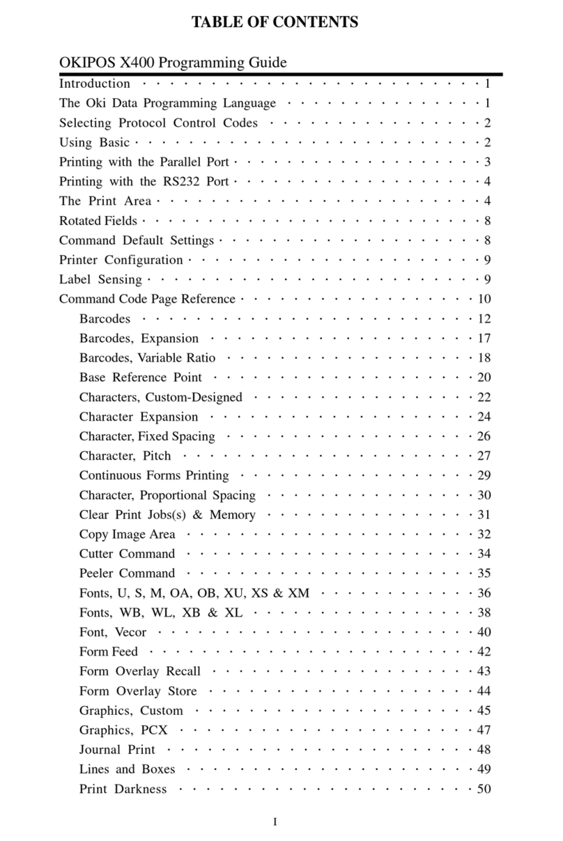
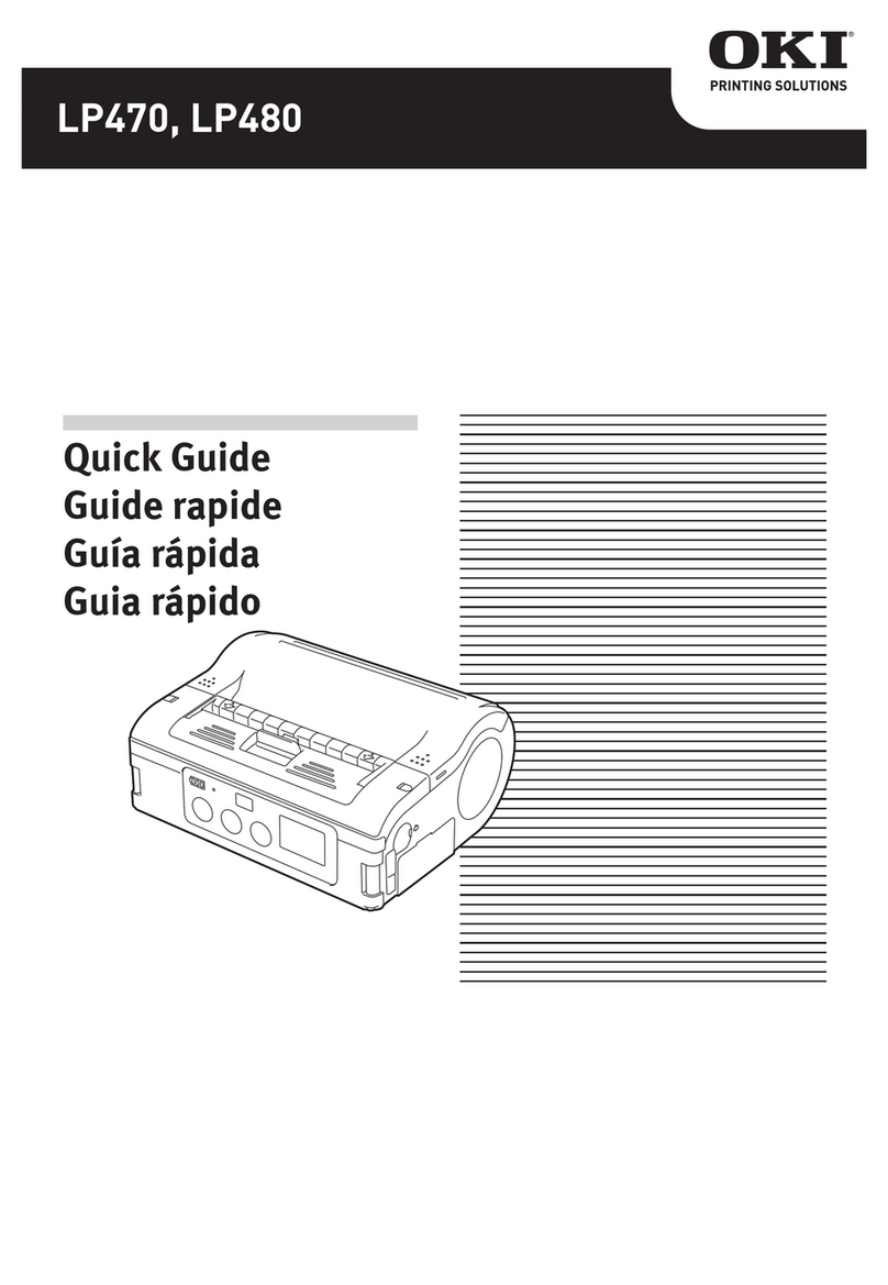
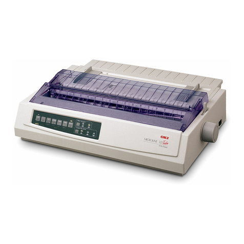
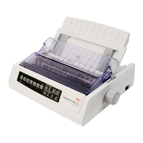
Oki Microline 320 Turbo D1 User manual

Oki Data CONFIDENTIAL
123456
Rev Date DCO No. Contents Design Approval
BOM Use for Certification Body
Approval
Check
Date Drawing No.
Name
Design
.....................................................................................................
.....................................................................................................
Drawing No. Name
Related drawings
MICROLINE 320/321 Turbo PRINTER
MICROLINE 3320/3321 PRINTER
(
OEL
)
Maintenance Manual
(ODA/OEL/INT/RUSSIA/HASAR/ADP/BANAMEX)
[Rev. 4]
No.01
42089201TH
ML320/321Turbo
ML3320/3321(OEL)
Maintenance Manual
1
123
2002-03-28
Yukio Okawara Minoru Kanno
42089201TL ML320/321Turbo ML3320/3321(OEL) Disassembly for Maintenance
42089201TR ML320/321Turbo ML3320/3321(OEL) RSPL
Minoru Kanno
2 2006-11-01 SW4-0462 Change for RoHS Minoru Kanno Minoru Kanno
3 2007-03-30 SW4-0551 Change for Energy Star Minoru Kanno Minoru Kanno
4 2009-02-17 SG2-0028 Addition of “Warning”, etc. Tomoyo Sugiyama Yoshinori Fujisawa

42089201TH Rev.4 2 /
Oki Data CONFIDENTIAL
1 2002-03-28 ISSUE
2 2006-11-01 For RoHS ODS M.Kanno
3 2007-03-30 For Energy Star ODS M.Kanno
4 2009-02-17 50, 69 Addition of “Warning”, EP5 T. Sugiyama
etc.
Rev.No. Date No.
Corrected items
Page Description of change
Person in
change
Document Revision History

42089201TH Rev.4 3 /
Oki Data CONFIDENTIAL
PREFACE
This maintenance manual describes how to maintain the Microline 320/321Turbo,Microline 3320/3321
printer in the field.
This manual is for customer engineers.
For further information, refer to the Users Manual for handling or operating the equipment.
The relation between the destination point and the model name of this printer is as follows.
Destintion point
For OEL Microline 3320/3321
For other Microline 320/321 Turbo

42089201TH Rev.4 4 /
Oki Data CONFIDENTIAL
CONTENTS
1. CONFIGURATION ...........................................................................................6
1.1. Standard Printer Configuration ..................................................................................... 6
1.2 Options .......................................................................................................................... 7
2. THEORY OF OPERATION .............................................................................9
2.1 Electrical Operation ....................................................................................................... 9
2.1.1 Summary .......................................................................................................... 9
2.1.2 Microprocessor and the Peripheral Circuit ..................................................... 9
2.1.3 Initialization..................................................................................................... 15
2.1.4 Parallel Interface Control ............................................................................... 16
2.1.5 Universal Serial Bus (USB) (at USB Ver.) ................................................... 17
2.1.6 Print Control ................................................................................................... 19
2.1.7 SP/LF Motor Control...................................................................................... 21
2.1.8 Operation Panel ............................................................................................. 23
2.1.9 Alarm Circuit .................................................................................................. 25
2.1.10 Power Supply Circuit ..................................................................................... 27
2.2 Mechanical Operation ................................................................................................. 28
2.2.1 Printhead Mechanism and Operation (See Figure 2-2.).............................. 28
2.2.2 Spacing Operation (See Figure 2-4.) ........................................................... 31
2.2.3 Head Gap Adjusting (See Figure 2-5.)......................................................... 32
2.2.4 Ribbon Drive (See Figure 2-6.) .................................................................... 34
2.2.5 Paper Feed Operation ................................................................................... 35
2.2.6 Paper Detection Mechanism (See Figure 2-15.).......................................... 45
2.2.7 Automatic Sheet Feed ................................................................................... 47
2.2.8 Paper Park Function (Continuous paper) ..................................................... 49
3. ASSEMBLY/DISASSEMBLY.........................................................................50
3.1 Precaution for Parts Replacement ............................................................................. 50
3.2 Service Tools .............................................................................................................. 51
3.3 Disassembly/Reassembly Procedure ......................................................................... 52
3.3.1 Printhead ........................................................................................................ 54
3.3.2 Ribbon Protector ............................................................................................ 55
3.3.3 Pull-up Roller Assy ........................................................................................ 56
3.3.4 Upper Cover Assy, Access Cover Assy and Sheet Guide Assy ................ 57
3.3.5 Gear Case Assy ............................................................................................ 58
3.3.6 PC Connector ................................................................................................ 59
3.3.7 Space Motor, Guide Roller Assy .................................................................. 60
3.3.8 Space Rack.................................................................................................... 61
3.3.9 Carriage Cable ............................................................................................... 62
3.3.10 Backup Roller Holder Assy ........................................................................... 63
3.3.11 Platen Assy .................................................................................................... 64
3.3.12.1Driver Board (DVE/DVF) (at USB Ver.) ....................................................... 65
3.3.12.2Driver Board (SDF) (at non USB Ver.) ........................................................ 66
3.3.13 LF Motor......................................................................................................... 67
3.3.14 Operation Panel PCB (LEOP)....................................................................... 68
3.3.15 Control/Power Supply Board (AOE/AOU/AOO) ............................................ 69
3.3.16 Transformer Assy........................................................................................... 70
3.3.17 Change Lever and Gears.............................................................................. 71
3.3.18 Carriage Shaft ................................................................................................ 72
3.3.19 Paper Pan ...................................................................................................... 73
3.3.20 Rear Tractor Assy ......................................................................................... 74
42089201TH Rev.4 5 /
Oki Data CONFIDENTIAL
3.3.21 Rear Pressure Assy ...................................................................................... 75
3.3.22 Switch Lever .................................................................................................. 76
4. ADJUSTMENT ...............................................................................................77
5. CLEANING AND LUBRICATION .................................................................85
5.1 Cleaning ...................................................................................................................... 85
5.2 Lubrication ................................................................................................................... 86
6. TROUBLESHOOTING AND REPAIR...........................................................94
6.1 Items to Check Before Repair ................................................................................... 94
6.2 Troubleshooting Table ................................................................................................ 94
6.3 Lamp Display .............................................................................................................. 95
6.4 Connection Circuit Check for Printhead and SP/LF Motor ....................................... 99
6.5 Troubleshooting flow chart ....................................................................................... 101
APPENDIX A PCB LAYOUT..............................................................................113
APPENDIX B RS-232C SERIAL INTERFACE BOARD (OPTION)..................115

42089201TH Rev.4 6 /
Oki Data CONFIDENTIAL
1. CONFIGURATION
1.1. Standard Printer Configuration
This printer consists of the following assemblies:
Figure 1-1 Configuration
Sheet guide assy Platen knob
Access cover
assy
Upper cover
Control/Power supply assy
Traansformer assy
Pull-up roller assy
Operation panel assy
Main chassis assy
Driver board
CSF
connector cover
(at USB Ver.)

42089201TH Rev.4 7 /
Oki Data CONFIDENTIAL
1.2 Options
(1) Cut sheet feeder unit (CSF)
(Narrow and wide versions available)
Dual-bin CSF Single-bin CSF
Attachment assy
(2) Pull-tractor assy

42089201TH Rev.4 8 /
Oki Data CONFIDENTIAL
(3) Bottom push tractor unit
(5) Option I/F Board
• RS232C
• RS422A
• Current Loop
• NIC (Network version only)
(4) Roll paper stand (Narrow only)

42089201TH Rev.4 9 /
Oki Data CONFIDENTIAL
2. THEORY OF OPERATION
2.1 Electrical Operation
The electrical operation of the printer circuit is described in this section.
2.1.1 Summary
Fig. 2-1 shows the block diagram of the printer.
The control board is made up of the microprocessors, peripheral circuits, drive circuits, sensors
and interface connectors.
The power to the control board is supplied by the power board through the connector cord.
The power to other electrical parts is also distributed through the connectors within the control
board.
2.1.2 Microprocessor and the Peripheral Circuit
(1) Microprocessor (67X640)
This processor is a CMOS single-chip computer with integrated peripheral device functions
and a 16 bit MPU core, all OKI original architecture.
The processor has a 20 bit address bus and a 16 bit data bus.
It is capable of accessing up to 4M bit program memory and 128K bytes of data memory.
The following characteristics are also provided:
• Built-in type data memory of 512 bytes
• 8-bit 4-channel A/D converter ×1
• 16-bit automatic reload timer ×2
• 8-bit serial port ×2
• 8-bit parallel port ×3 (bitwise I/O specification available)
And others.
The function of this microprocessor is to provide a central mechanism for the entire printer
by executing the control program through the LSI and driver circuits.

42089201TH Rev.4 10 /
Oki Data CONFIDENTIAL
Figure 2-1
HTEMP
12.288
MHz
4
Vcc-Level
HTEMP
SWRD
HEADGAP
A/D
PE-SENSOR
OPERATION
PANEL
Serial
Alarm
-circuit HD alarm
Power-off
Transformer Rectifier
circuit Regulaticn
circuit
40 volt
8 volt
5 volt 15 volt
Reset
circuit
SWRD
I/F-IPT
Print-IPT
EEPROM
1Kbits
Micro
processor
ADDRESS
ROM
AD-BUS
DRAM
4Mbit
ROM
LSI
RESET
5VD
Vcc-Level
Fuse
40 V
LF
driver
SP
driver
HD alarm
Head
driver
Photo sensor
M
M
SP
LF
HTEMP
(opt.)
Serial-
I/F
(opt.)
Roll paper
stand
(opt.)
CSF
USB
I/F
USB
controller
(at USB Ver.)
AC-input
AC 10 volt
Divider
Release-SW
Bottom-SW
HEADGAP-SWHEADGAP
Para-
I/F
Fuse
40 V
256Kx16bits
8/16
Mbit
4/8/16
Mbit

42089201TH Rev.4 11 /
Oki Data CONFIDENTIAL
(2) Program ROM
This is a 256K/512K/1024K ×16 bits (4/8/16M bit) MASK ROM or FLASH ROM with the
control program for the printer stored. The MPU executes instructions under this program.
The program ROM is assigned to the program memory area of the MPU and is fetched
by the PSEN signal of the MPU.
The following shows the operation of the memory access.
MPU CLOCK
A0~A17/A18/A19
PG-N
PSEN-N
D0~D15
Program Program Program
IN IN IN
CSO
PSEN
CE
OE
PG-N
D0~D15
A0~A17/A18/A19
MPU ROM

42089201TH Rev.4 12 /
Oki Data CONFIDENTIAL
(3) RAM
The RAM is CMOS dynamic RAM with 256K ×16bits (4Mbit), and used as buffers (such
as receiving buffer, printing buffer, DLL buffer and working buffer).
The following shows the examples of the memory access operation.
A0~A7
CAS-N UCAS-N
LCAS-N
WE-N
WRH-N
WRL-N
RAMMPU
P03
P04
CS1
WRL
P11
RD OE
D0~D15
RAS
UCAS
LCAS
WE
T1 T2 T3Clockout*
A0~A7
LGAS
RD
D0~D15
(Read)
WE
D0~D15
(Write)
16-bit bus, byte instruction
LS139
ALS11
* Clockout is provided when the original excitation is selected.

42089201TH Rev.4 13 /
Oki Data CONFIDENTIAL
(4) EEPROM
The EEPROM is a CMOS serial I/O type memory which is capable of electrically erasing
and writing 1,024 bits.
The EEPROM contains menu data.
The following shows the memory access operation.
MPU EEPROM
EEDIN-P
EECS-P
EEDOUT-P
EECLK-P
P24
P27
P25
P26
D1
CS
DO
SK
ReadyBus
twp
D0D15A0A5
11 0
Start
code
Operation
code Address Data
t
CS
PRE = O
PE
EECS-P
EECLK-P
EEDIN-P
EEDOUT-P
Address
Start
code
Operation
code
EEDOUT-P
EEDIN-P
EECLK-P
EECS-P
D15 D0 D15 D0 D15
0
A0A5
0
11
t
CS
PRE = O
PE = X
Read cycle timing (READ)
Write cycle timing (WRITE)

42089201TH Rev.4 14 /
Oki Data CONFIDENTIAL
(5) LSI
This LSI detects and controls the SP motor speeds by monitoring the two phase sensor
signals obtained from the DC motors and modifying the excitation phases as appropriate.
This LSI is connected in multiplex to the MPU.
P07
MPU A/D bus LSI
RD
WRL
P01
ALE
RDN
WRL
LSIC
Clockout*
A0~A19
LSICS
ALE
D0~D15
(Read)
RD
D0~D15
(Write)
WRL
Address
Address
Data
Data
* Clockout is provided when the original
excitation is selected.

42089201TH Rev.4 15 /
Oki Data CONFIDENTIAL
2.1.3 Initialization
This printer is initialized when the power is turned on or when the I-PRIME-N signal is input
from the host side via the parallel interface.
For the initializing operation, the RST-N signal is first output from the reset circuit to reset the
MPUs and LSIs. When resetting ends, the program starts and the LSIs are reset by MPU via
LSIRST-N. Reset operation by I-PRIME starts program to initialize, but does not reset the MPU.
The program here sets the mode of the LSI including the MPU, checks the memories (ROMs
and RAMs) and, after USB I/F control LSI initialization and USB I/F bus opening, performs
carriage homing operation and LF motor phase setting.
Finally, the program establishes the interface signals (P-I/F: ACK-P signal sending, and S-I/F:
BUSY-N signal off) and lights the SELECT lamp to inform the ready state for receiving to the
host side and ends the initialize operation.
(at USB Ver.)
End
I/F BUSY OFF
Serial
I/F
I/F ACK Send
Parallel
I/F
LF Motor Phase
Initialization
Carriage Homing
RAM Clear
LSI Initial Setting
and I/F Busy ON
USB I/F Bus Open
USB I/F control LSI
Initial
External RAM
CHECK
LSI RESET
ROM CHECK
Internal RAM
CHECK
MPU
Initial Setting
MPU RESET
Start

42089201TH Rev.4 16 /
Oki Data CONFIDENTIAL
2.1.4 Parallel Interface Control
The parallel data input from the host to the interfaced LSI is latched to its internal register at
the falling edge of the STROBE-N signal.
At the same time, the LSI sets the BUSY signal to the high level to inform the host that the
data is being processed, and outputs the RXD signal to inform the MPU of data reception. The
data is read upon receiving the RD-N signal from the MPU.
When the data processing ends, the BUSY signal is set to off and the ACK-N signal in sent
to request the next data. When reception is impossible because the buffer is full, the BUSY signal
is sent to request stopping of data transmission.
A/D bus
MPU LSI
NBSY
ACK
NSTB
RXD
P16 NRXD
Receive Data
CN1
BUSY
ACK-N
STB-N
Data
1 to 8
STROBE
BUSY
ACK
RXD
2~8 s
500ns max.

42089201TH Rev.4 17 /
Oki Data CONFIDENTIAL
2.1.5 Universal Serial Bus (USB) (at USB Ver.)
Universal Serial Bus Specification Revision 1.0 compliance.
1) Connector
•Printer Side : “B”Receptacle (Upstream Input to the USB Device)
•Cable Side : Series “B”Plug
2) Cable
•Cable Length : Approx 1.8m (A cable must be met USB Spec Rev 1.1 for normal
operation)
Note:
Cable is not supplied.
3) Table of USB I / F signals
Contact Signal Name Typical Wiring
Number Assignment
1 Vbus Red
2 D - White
3 D + Green
4 GND Black
Shell Shield Drain Wire
4) Connector pin arrangement
2
34
1
5) Mode & Class of Device
•Full - speed Driver
•Self - powered Device
6) Data Signaling Rate
•Full - speed function - 12Mb/s ±0.25%(2500ppm)
7) Receive Buffer
•2044K Bytes
8) Interface circuit
3.3 V
1.5 k
Ω
Rs = 22
Ω
TxD+ Rs
Full-speed
Buffer
Rs
TxD-

42089201TH Rev.4 18 /
Oki Data CONFIDENTIAL
9) Signal Level
•Input / Output Level
Parameter
Input Levels :
High (driven)
High (floating)
Low
Output Levels :
Low
High (driven)
Output Signal Crossover Voltage
Symbol
V
IH
V
IHZ
V
IL
OL
OH
V
CRS
Min.
2.0
2.7
0.0
2.8
1.3
Max.
3.6
0.8
0.3
3.6
2.0
Units
V
V
V
V
V
V

42089201TH Rev.4 19 /
Oki Data CONFIDENTIAL
2.1.6 Print Control
Print data is transmitted as parallel data (HEAD1~HEAD9) from LSI to print head. LSI generates
print timing and drive time.
HEAD DRIVE TIMING CHART
DT1
DT2
HEAD
DRIVE CURRENT
Print Data
MPU LSI
DRIVER
HEAD1-N~
HEAD9-N
Print Data Print Head
Control/Power Supply Board
A/D bus
HEAD1~
HEAD9
Driver Board

42089201TH Rev.4 20 /
Oki Data CONFIDENTIAL
(d) Simultaneous Compensation of the number of impact pins
The MPU is provided with the compensation table for each pin to make necessary
compensation.
Print Compensation Control
The print compensation can be made as shown below:
(a) Voltage compensation (See 2.1.8 “Alarm Circuit.”)
(b) Temperature compensation (See 2.1.8 “Alarm Circuit.”)
(c) Pin stroke compensation
As shown in the drawing left, the stroke length
up to the platen is different for each pin.
Number of impact pins Few Many
Drive time Short Long
Print Head
Time
Pin 3~6
Pin 1, 2,
8, 9
Pin coil
current
Pin 1, 2
3~6
8, 9
Platen
Head Gap Range 1 2 3 4 5
Print speed 100% 95% 85% 85% 80%
Drive time Short Long
(e) Print mode compensation
According to the thickness of the printing medium, the print mode is compensated
as shown in the table below:
(Drive time lengthens at each step.)
Other manuals for Microline 320 Turbo D1
3
This manual suits for next models
3
Table of contents
Other Oki Printer manuals

Oki
Oki C130n Quick start guide

Oki
Oki 1624N User manual

Oki
Oki C3200n User manual

Oki
Oki CX3641 MFP User manual

Oki
Oki OKIPAGE 8w Lite User manual

Oki
Oki LP441b User manual

Oki
Oki ML8810 User manual

Oki
Oki C7500 V2 Installation and maintenance instructions

Oki
Oki OKIPAGE8c User manual

Oki
Oki C5100n User manual