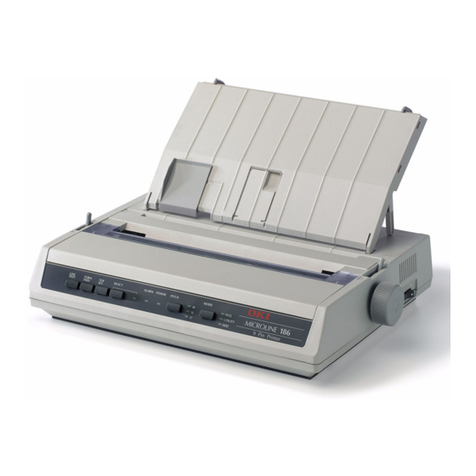
Oki MICROLINE MX Series User manual

Quick Setup Guide
MICROLINE MX Series
Mantenimiento Periféricos Informáticos SL C/Canteras, 15 28860 Paracuellos de Jarama Tel: 00 34 917481604 WEB: https://mpi.com.es

Mantenimiento Periféricos Informáticos SL C/Canteras, 15 28860 Paracuellos de Jarama Tel: 00 34 917481604 WEB: https://mpi.com.es

This Quick Setup Guide contains a
CD-ROM with the following materials:
•The User’s Manual
•Programmer’s Reference Manuals
•Useful utility programs
The CD-ROM is in a plastic pocket in
the back cover.
Save this guide. If you move or pack
the printer in the future, you will need to
reverse the instructions in this guide.
NOTICE
Mantenimiento Periféricos Informáticos SL C/Canteras, 15 28860 Paracuellos de Jarama Tel: 00 34 917481604 WEB: https://mpi.com.es

Mantenimiento Periféricos Informáticos SL C/Canteras, 15 28860 Paracuellos de Jarama Tel: 00 34 917481604 WEB: https://mpi.com.es

5
Table of Contents
Basic Installation Procedures................... 7
Printer Component Locations...............................................8
Remove Packing Materials...................................................9
Adjust The Paper Supports ................................................14
Release The Paper Chains – Cabinet Model .....................15
Remove Tags – Cabinet Model..........................................16
Remove The Shipping Restraints From
The Power Paper Stacker (If Equipped).............................17
Attach The Control Panel Overlay......................................20
Connect The Interface And Power Cables.........................21
Cabinet Model ...............................................................21
Interface Connections (Cabinet And Pedestal) .............23
Pedestal Model .............................................................24
Install The Ribbon And Paper ............................................25
Load The Ribbon...........................................................25
Load The Paper (Standard Configuration)....................28
Set The Top-Of-Form .........................................................35
Adjust The Passive Paper Stacker – Cabinet Model..........38
Power Paper Stacker Option..............................................39
Power Paper Stacker Component Locations ................39
Setting Up The Power Paper Stacker ...........................40
Loading And Starting The Power Paper Stacker ..........43
Checking The Paper Feed – Cabinet Model ......................45
Attach The Input Paper Shelf And Output Basket –
Pedestal Model...................................................................46
Quick Access – Pedestal Model.........................................48
Checking The Paper Feed – Pedestal Model.....................50
The Control Panel ..............................................................51
Printer Self-Test .................................................................52
Mantenimiento Periféricos Informáticos SL C/Canteras, 15 28860 Paracuellos de Jarama Tel: 00 34 917481604 WEB: https://mpi.com.es

Table of Contents
6
Quick Setup Menu..............................................................52
Print A Test Page ...............................................................57
Mantenimiento Periféricos Informáticos SL C/Canteras, 15 28860 Paracuellos de Jarama Tel: 00 34 917481604 WEB: https://mpi.com.es

7
Basic Installation
Procedures
This Quick Setup Guide provides general information for setting up
and testing your printer. For detailed information, refer to your
User’s Manual which is on the CD-ROM attached to the back cover
of this guide.
Mantenimiento Periféricos Informáticos SL C/Canteras, 15 28860 Paracuellos de Jarama Tel: 00 34 917481604 WEB: https://mpi.com.es

Printer Component Locations
8
Printer Component Locations
Familiarize yourself with the names and locations of the printer
components, shown in Figure 1, before continuing with the rest of
the installation procedures.
Figure 1. Printer Component Locations
Ribbon Spool
Ribbon Hub
Blue Tractor
Lock (2)
Paper Support
Tractor (2)
Vertical
Position Knob
Platen Lever
Ribbon Guide (2)
Ribbon
Splined
Shaft
Platen Stop
Barcode
Hammer Bank
Cover and
Ribbon Mask
Date Code Label
Barcode Sensor
Mantenimiento Periféricos Informáticos SL C/Canteras, 15 28860 Paracuellos de Jarama Tel: 00 34 917481604 WEB: https://mpi.com.es

9
Remove Packing Materials
CAUTION
To avoid shipping damage, reinstall the shipping restraints
whenever you move or ship the printer.
Save the cardboard packing, foam blocks, and bubble wrap along
with the other packing materials in case you need to move the
printer. If it is necessary to move the printer, reinstall the shipping
restraints, reversing the steps in this section.
Figure 2. Removing the Protective Film
1. Peel the tape off carefully and lift the protective film off the
control panel message display.
Protective Film
Control Panel
Message Display
Remove Packing Materials
Mantenimiento Periféricos Informáticos SL C/Canteras, 15 28860 Paracuellos de Jarama Tel: 00 34 917481604 WEB: https://mpi.com.es

Remove Packing Materials
10
Figure 3. Removing the Sample Configuration Printout
2. Open the blue tractor doors.
3. Move the tractor locks to the middle position to unlock them.
4. Raise the platen lever to the fully open (raised) position.
5. Remove the envelope containing the sample configuration
printout.
6. Store the envelope in the pouch attached to the left interior side
of the cabinet.
7. Remove the cardboard packing.
Envelope
Platen Lever
Blue Tractor
Door (2)
A
A
Blue Tractor
Lock (2)
Mantenimiento Periféricos Informáticos SL C/Canteras, 15 28860 Paracuellos de Jarama Tel: 00 34 917481604 WEB: https://mpi.com.es

11
Figure 4. Removing the Hammer Bank Protective Foam
8. Remove the hammer bank protective foam between the ribbon
mask and the platen.
Hammer Bank
Protective Foam
Remove Packing Materials
Mantenimiento Periféricos Informáticos SL C/Canteras, 15 28860 Paracuellos de Jarama Tel: 00 34 917481604 WEB: https://mpi.com.es

Remove Packing Materials
12
Figure 5. Removing the Platen Protective Foam
9. Rotate the platen protective foam toward the front of the printer
and out from under the support shaft.
10. Remove the platen protective foam.
Platen Protective
Foam
Mantenimiento Periféricos Informáticos SL C/Canteras, 15 28860 Paracuellos de Jarama Tel: 00 34 917481604 WEB: https://mpi.com.es

13
Figure 6. Removing the Six Wooden Blocks
11. Remove the six wooden blocks.
Wooden Block (6)
Wooden Block
Wooden Block
Wooden Block
Wooden Block
Wooden Block
Remove Packing Materials
Mantenimiento Periféricos Informáticos SL C/Canteras, 15 28860 Paracuellos de Jarama Tel: 00 34 917481604 WEB: https://mpi.com.es

Adjust The Paper Supports
14
Adjust The Paper Supports
Figure 7. Adjusting Paper Supports
Squeeze the paper support tabs and slide the blue paper supports
inward until each one is approximately four inches from its
corresponding blue tractor door.
Blue Paper Support (2)
Blue Tractor
Door (2)
Paper Support
Tab (2)
A
A
Mantenimiento Periféricos Informáticos SL C/Canteras, 15 28860 Paracuellos de Jarama Tel: 00 34 917481604 WEB: https://mpi.com.es

15
Release The Paper Chains – Cabinet Model
NOTE: Steps 1– 3 in this section are for the passive stacker. If you
have the power paper stacker installed, skip this procedure
and go to “Remove The Shipping Restraints From The
Power Paper Stacker (If Equipped)” on page 17.
Figure 8. Releasing the Paper Stacking Chains
1. Open the cabinet rear door.
2. Cut the tie wraps and release the paper stacking chains from
the bags at the top rear of the printer frame. Remove the tie
wraps and bags.
3. Make sure each chain hangs freely with no kinks or knots.
Tie Wrap (2) Paper Chain (8)
Bag (2)
Release The Paper Chains – Cabinet Model
Mantenimiento Periféricos Informáticos SL C/Canteras, 15 28860 Paracuellos de Jarama Tel: 00 34 917481604 WEB: https://mpi.com.es

Remove Tags – Cabinet Model
16
Remove Tags – Cabinet Model
NOTE: If you have the power paper stacker installed, skip this
procedure and go to “Remove The Shipping Restraints
From The Power Paper Stacker (If Equipped)” on page 17.
Figure 9. Removing Tags from the Cabinet Models
1. Remove the tie wrap attached to the passive stacker paper
fence. The tie wrap is marked with a large, red tag.
2. Close the cabinet rear door.
Passive Stacker
Paper Fence
(if equipped)
Tie Wrap
Red Tag
Mantenimiento Periféricos Informáticos SL C/Canteras, 15 28860 Paracuellos de Jarama Tel: 00 34 917481604 WEB: https://mpi.com.es

17
Remove The Shipping Restraints From
The Power Paper Stacker (If Equipped)
This section applies only to printers with the power stacker
installed.
Special packaging protects the power stacker mechanisms from
damage during shipment. This section describes how to remove
the shipping restraints before you operate the printer.
Save the packaging materials. You will need to reinstall them if you
decide to move or ship the printer. To reinstall the packaging
materials, reverse the steps in this section.
IMPORTANT
To avoid shipping damage, install the shipping restraints
whenever you move or ship the printer.
Remove The Shipping Restraints From The Power Paper Stacker (If Equipped)
Mantenimiento Periféricos Informáticos SL C/Canteras, 15 28860 Paracuellos de Jarama Tel: 00 34 917481604 WEB: https://mpi.com.es

Remove The Shipping Restraints From The Power Paper Stacker (If Equipped)
18
Figure 10. Removing the Shipping Restraints
1. Open the rear door panel.
2. Remove the five tie wraps.
3. Raise the power paper stacker frame to its highest position by
pulling up on the elevator lift handle.
4. Remove the plastic bags from the paper chains.
Tie Wrap (5)
Plastic Bag (3)
Elevator Lift
Handle
Mantenimiento Periféricos Informáticos SL C/Canteras, 15 28860 Paracuellos de Jarama Tel: 00 34 917481604 WEB: https://mpi.com.es

19
Figure 11. Replacing the Paper Tent
5. Remove the tape holding the paper tent.
6. Place the paper tent onto the pull-out drawer.
Paper Tent
Tape
Remove The Shipping Restraints From The Power Paper Stacker (If Equipped)
Mantenimiento Periféricos Informáticos SL C/Canteras, 15 28860 Paracuellos de Jarama Tel: 00 34 917481604 WEB: https://mpi.com.es

Attach The Control Panel Overlay
20
Attach The Control Panel Overlay
Figure 12. Attaching Control Panel Overlay
1. Choose the overlay label in the appropriate language.
2. Open the printer cover.
3. Peel the protective backing off the overlay and the blue tape
from the window.
4. Press the overlay into place.
Overlay Label
Mantenimiento Periféricos Informáticos SL C/Canteras, 15 28860 Paracuellos de Jarama Tel: 00 34 917481604 WEB: https://mpi.com.es
Other manuals for MICROLINE MX Series
1
This manual suits for next models
1
Table of contents
Other Oki Printer manuals

Oki
Oki C911dn User manual

Oki
Oki C5500n Series User manual

Oki
Oki B6100n User manual

Oki
Oki C7400 User manual

Oki
Oki ES1624n MFP Instruction Manual

Oki
Oki OKIPAGE14e Use and maintenance manual

Oki
Oki C3200n Service manual

Oki
Oki OKIPAGE10ex User manual

Oki
Oki C310dn User manual

Oki
Oki ML490 Series User manual