Oki OKIPAGE 6e User manual

All specifications are subject to change without notice.
Approval
OKIPAGE6e/6ex
LED Page Printer
Maintenance Manual
ODA/OEL/INT

PREFACE
This Maintenance Manual describes the field maintenance methods for OKIPAGE 6e and OKIPAGE
6ex LED Page Printers.
This manual is written for use by service persons. Please note that you should refer to the Printer
Handbook for the handling and operating methods of the equipment.

CONTENTS
1. CONFIGURATION..................................................................................... 1 - 1
1.1 System Configuration ........................................................................ 1 - 1
1.2 Printer Configuration.......................................................................... 1 - 2
1.3 Optional Configuration....................................................................... 1 - 3
1.4 Specification ...................................................................................... 1 - 5
1.5 Safety Standards ............................................................................... 1 - 7
1.5.1 Certification Label.................................................................................... 1 - 7
1.5.2 Warning Label .........................................................................................1 - 8
1.5.3 Warning/Caution Marking ........................................................................ 1 - 9
2. OPERATION DESCRIPTION .................................................................... 2 - 1
2.1 Control Board..................................................................................... 2 - 4
2.2 PS Board ........................................................................................... 2 - 6
2.3 RAM Board ........................................................................................ 2 - 7
2.4 Power Supply Board.......................................................................... 2 - 8
2.5 Electrophotographic Process............................................................. 2 - 10
2.5.1 Electrophotographic Process Mechanism ............................................... 2 - 10
2.5.2 Electrophotographic Process .................................................................. 2 - 13
2.5.3 Process Operation Descriptions .............................................................. 2 - 16
2.6 Paper Jam Detection ......................................................................... 2 - 27
2.7 Cover Open ....................................................................................... 2 - 30
2.8 Toner Low Detection.......................................................................... 2 - 31
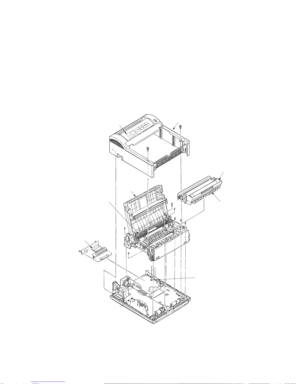
3. PARTS REPLACEMENT........................................................................... 3 - 1
3.1 Precautions for Parts Replacement................................................... 3 - 1
3.2 Parts Layout....................................................................................... 3 - 3
3.3 How to Change Parts......................................................................... 3 - 6
3.3.1 Upper Cover ............................................................................................ 3 - 7
3.3.2 Stacker ....................................................................................................3 - 8
3.3.3 LED Head ................................................................................................ 3 - 9
3.3.4 Eject Roller Assy ..................................................................................... 3 - 10
3.3.5 Pulse Motor (Main) .................................................................................. 3 - 11
3.3.6 Pulse Motor (Registration)....................................................................... 3 - 12
3.3.7 Lower Base Unit ...................................................................................... 3 - 13
3.3.8 Motor Assy ..............................................................................................3 - 14
3.3.9 Hopping Roller Assy ................................................................................3 - 15
3.3.10 Stacker Cover Assy ................................................................................. 3 - 16
3.3.11 Registration Roller ................................................................................... 3 - 17
3.3.12 Transfer Roller.........................................................................................3 - 18
3.3.13 Fusing Unit Assy .....................................................................................3 - 19
3.3.14 Back-up Roller .........................................................................................3 - 20
3.3.15 Sensor Plate (Inlet)..................................................................................3 - 21
3.3.16 Toner Sensor (Adhesion) ........................................................................ 3 - 22
3.3.17 Sensor Plate (Outlet) ............................................................................... 3 - 23
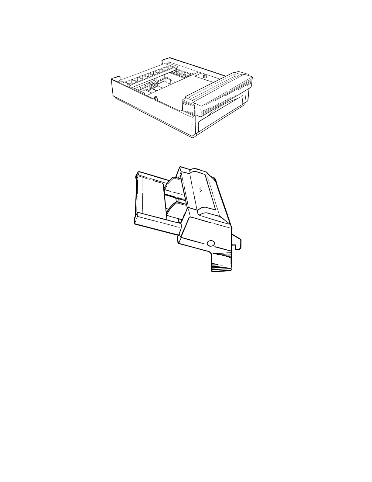
3.3.18 Manual Feed Guide Assy ........................................................................ 3 - 24
3.3.19 Sensor Plate (Paper Supply) ................................................................... 3 - 25
3.3.20 Main Control PCB.................................................................................... 3 - 26
3.3.21 Power Supply Board and Contact Assy .................................................. 3 - 27

3.3.22 Transformer............................................................................................. 3 - 28
3.3.23 Cassette Guide L.....................................................................................3 - 29
3.3.24 Cassette Guide R .................................................................................... 3 - 30
4. ADJUSTMENT........................................................................................... 4 - 1
4.1 Adjustment......................................................................................... 4 - 1
4.1.1 Maintenance Functions ........................................................................... 4 - 1
4.2 Adjustment......................................................................................... 4 - 10
4.2.1 Maintenance Modes and Functions ........................................................ 4 - 10
4.3 Adjustment When Replacing a Part................................................... 4 - 12
4.3.1 Adjustment at the Time of Part Replacement
(OKIPAGE6e 300dpi LED head) ............................................................. 4 - 12
4.3.2 Adjustment When Replacing a Part (OKIPAGE6ex 600dpi LED head) .. 4 - 14
4.3.3 Uploading / Downloading EEPROM data................................................ 4 - 17
5. PERIODICAL MAINTENANCE ................................................................. 5 - 1
5.1 Periodical Replacement Parts ........................................................... 5 - 1
5.2 Cleaning............................................................................................. 5 - 1
5.2.1 Cleaning of LED Lens Array.................................................................... 5 - 1
6. TROUBLESHOOTING PROCEDURES .................................................... 6 - 1
6.1 Troubleshooting Tips ......................................................................... 6 - 1
6.2 Check Points before Correcting Image Problems.............................. 6 - 1
6.3 Tips for Correcting Image Problems .................................................. 6 - 1
6.4 Preparation for Troubleshooting ........................................................ 6 - 2
6.5 Troubleshooting Flow ........................................................................ 6 - 3
6.5.1 Status Message/Trouble List ................................................................... 6 - 3
6.5.2 Status Message Troubleshooting............................................................ 6 - 24
6.5.3 Image Troubleshooting............................................................................6 - 36
7. WIRING DIAGRAM.................................................................................... 7 - 1
7.1 Interconnect Signal Diagram ............................................................. 7 - 1
7.2 PCB Layout and Connector Signal List ............................................. 7 - 3
7.3 Resistance Check.............................................................................. 7 - 15
7.4 Short Plug Setting.............................................................................. 7 - 17
8. PARTS LIST .............................................................................................. 8 - 1
Appendix A Centronics Parallel Interface................................................. A - 1
B LocalTalk (RS422) Serial Interface........................................ B - 1
C Diagnostics Test..................................................................... C - 1
D Maintenance Utility Overview................................................ D - 1
E Multi-Purpose Feeder Maintenance...................................... E - 1
F High Capacity Second Paper Feeder Maintenance............. F - 1

1. CONFIGURATION

1 - 1
1. CONFIGURATION
1.1 System Configuration
OKIPAGE 6e and OKIPAGE 6ex consist of control and engine blocks in the standard configura-
tion, as shown in Figure 1-1.
In addition, the options marked with asterisk(*) are available.
Figure 1-1
Power Supply
and Sensor PCB
Electrophotographic
Processing Unit
Paper Feed Mechanism
(First Tray Unit)
*OKIPAGE 6ex
*OKIPAGE 6e/6ex
: PS Board with RAM
: RAM Board
Main Control PCB
Operator Panel
(OKIPAGE 6ex Only)
Paper
Cassette
Face
Down
Stacker
Engine Unit
* : Optional
* Legal/Universal
Paper Tray
#
* Hight Capacity
Second Paper Feeder
* Multi-Purpose
Feeder

1 - 2
1.2 Printer Configuration
The printer unit consists of the following hardware components:
• Electrophotographic Processor
• Paper Feeder
• Main Control PCB
• Operator Panel (OKIPAGE 6ex Only)
• Power Supply Unit
• PS Board (OKIPAGE 6ex Only)
The printer unit configuration is shown in Figure 1-2.
Toner cartridge
(consumables)
Operator panel assy Upper cover
Image drum unit
(consumable)
Stacker cover assy
Fusing unit
PS Board
Main Control PCB
• L5C or L5D: OKIPAGE6e
• L6A : OKIPAGE 6ex
Power supply board
Figure 1-2

1 - 3
1.3 Optional Configuration
Theoptionsshown belowareavailable for usewithOKIPAGE 6eandOKIPAGE 6ex. Theseare
available separately from the printer unit.
(1) 1MB Memory Expansion Board (OKIPAGE 6e/6ex)
(2) SIMM Memory
OKIPAGE 6e :1/2/4/8/16 Mbyte
OKIPAGE 6ex :1/2/4/8/16/32 Mbyte
(3) Legal/Universal Paper Cassette/
Legal/Universal cassette
Cassette cover

1 - 4
(4) High Capacity Second Paper Feeder
(5) Multi-Purpose Feeder

1 - 5
1.4 Specification
(1) Type Desktop
(2) External dimensions Height 6.3” (160 mm)
(excludes protruding Width 12.6” (320 mm)
portion) Depth 14.17” (360 mm)
(3) Weight 8 kg
(4) Developing method Dry electrophotography
Exposing method LED stationary head
(5) Paper used <Type>
• Standard paper
– Xerox 4200 (20 lbs)
• Application paper (manual face-up feed)
– Label
– Envelope
– OHP paper (Transparency)
<Size>
• Standard sizes
– Letter (ODA)
– Legal (option)
– Executive
– Envelope
– A4
– A5
– B5
– A6
• Applicable sizes
– Width: 3.94” to 8.5” (100 to 216 mm)
– Length: 5.83” to 14” (148 to 355.6 mm)
<Thickness>
– Automatic feed: 16 to 24 lbs (60 to 90 g/m2)
– Manual feed: Label, OHP paper (transparency)
Envelope
(6) Printing speed First print: 17 sec.
Continuous print: 6 sheets/min. for letter size paper
Warm-up time: 60 sec. [at room temperature 77˚F
(25˚C) and rated voltage (120 VAC)]
(7) Paper feeding method Automatic feed or manual feed
(8) Paper delivery method Face down/face up
(9) Resolution 300 x 300 dots/inch (OKIPAGE 6e)
600 x 600 dots/inch (OKIPAGE 6ex)
600 x 1200 dots/inch (OKIPAGE 6ex)

1 - 6
(10) Power input 120 VAC +5.5%, –15%
230 VAC +15 %, –15%
(11) Power consumption Peak: Approx. 420W
Typical operation: Approx. 160W
Idle: Approx. 55W
Power save mode: Approx. 15W
(12) Temperature and humidity During operation: 50 to 90°F (10 to 32°C)
In storage: 14 to 110°F (–10 to 43°C)
(13) Noise During operation: 48 dB (A) or less
Standby: 38 dB (A) or less
(14) Consumables Toner cartridge kit 2,000 (5% duty)
Image drum cartridge 20,000 (at continuous printing)
15,000 (3 pages/job)
10,000 (1 page/job)

1 - 7
1.5 Safety Standards
1.5.1 Certification Label
The safety certification label is affixed to the printer at the location described below.
OKIPAGE 6e OKIPAGE 6ex
120V
OKIPAGE 6e OKIPAGE 6ex
230V

1 - 8
1.5.2 Warning Label
The warning labels are affixed to the sections which may cause bodily injury.
Follow the instructions on warning labels during maintenance.

1 - 9
1.5.3 Warning/Caution Marking
The following warning and caution markings are made on the power supply board.
ENGLISH
Heatsink and transformer core present risk of electric shock. Test before touching.
FRENCH
Le dissipateur thermique et le noyau du transformateur présentent des risques de choc
électrique. Testez avant de, manipuler.
SPANISH
Las disipadores de color el núcel del transformador pueden producir un choque eléctrico.
Compruebe antes de tocar.
PORTUGUESE
O dissipador de calor e o núcleo do fransiormador apresentam risco de choque elétrico. Teste
antes de focar.
ENGLISH
Circuits maybe live after fuses open.
FRENCH
Il se peut que les circuits soient sous tension une fois que les fusibles ont éfé rerirés.
SPANISH
Las circuitos pueden estar activos una vez que se hayan abierio los fusibles.
PORTUGUESE
Os circuitos podem estar energizados após os fusiveis se queimarem.
CAUTION

2. OPERATION DESCRIPTION

2 - 1
2. OPERATION DESCRIPTION
OKIPAGE 6e, OKIPAGE 6ex consists of a Main Control PCB, a power supply/sensor board, a
PostScript board (OKIPAGE 6ex), an operator panel and an electrophotographic process
mechanism.
The soft operator panel is used for operation and status display of OKIPAGE 6e and OKIPAGE
6ex.
The operator panel is used for operation and status display of OKIPAGE 6ex.
The OKIPAGE 6e and OKIPAGE 6ex receive data via the host I/F, these then decode, edit and
storethedatainmemory. Bitmapimagedata is successivelytransferredtotheLEDheadinone
dot line units.
OKIPAGE 6e block diagram is shown in Figure 2-1.
OKIPAGE 6ex block diagram is shown in Figure 2-2.

2 - 2
Figure 2-1 OKIPAGE 6e Block Diagram
1MB Memory Board
(Option)
Charge roller
Transfer roller
Developing
roller
Toner supply
roller
Cleaning
roller
Heater
High voltage
generation
circuit
Heater drive
circuit
LED Head
FAN
Drum Motor
Registration Motor
1 Chip CPU
Reset
circuit
Low voltage
generation circuit
AC
transformer
Toner low sensor
Paper out sensor
Outlet sensor
Paper sensor
Inlet sensor 2
Inlet sensor 1
Cover
open
switch
AC IN
+8V -8V 0V +5V
+5V
+30V
CH TR DB
HEAT ON
Filter circuit
Centronics
parallel I/F
EEPROM
Power Supply
Board
FAN ALM
FAN Driver
LSI
M
M
Drum motor &
Registration motor
drive circuit
L5C- or L5D For optional
RAM board
16 bits
DATA
BUS
Program & Font
ROM
4MB Mask ROM
7407
Thermistor
High Capacity
Second Paper
Feeder (Option)
Multi-Purpose
Feeder (Option)
Resident RAM
1M x 16 DRAM(2M Bytes)
L5D
Resident RAM
256k x 16 DRAM x 2
(1M Bytes)
L5C

2 - 3
Figure 2-2 OKIPAGE 6ex Block Diagram
PS Board with RAM
LocalTalk I/F (RS422 I/F)
Charge roller
Transfer roller
Developping
roller
Toner supply
roller
Cleaning
roller
Heater
High voltage
generation
circuit
Heater drive
circuit
LED Head
FAN
Drum Motor
Registration Motor
Resident RAM
1M x 16 DRAM
(2MB)
1 Chip CPU
Reset
circuit
Low voltage
generation circuit
AC
transformer
Toner low sensor
Paper out sensor
Outlet sensor
Paper sensor
Inlet sensor 2
Inlet sensor 1
Cover
open
switch
AC IN
+8V -8V 0V +5V +30V
CH TR DB
HEAT ON
Filter circuit
Centronics
parallel I/F
EEPROM
Power Supply
Board
FAN ALM
FAN Driver
M
M
Drum motor &
Registration motor
drive circuit
L6A- For optional
RAM board
DATA
BUS
32 bit
16 bit
16 bit
Program & Font
ROM
4MB Mask ROM
7407
High Capacity
Second Paper
Feeder (Option)
Multi-Purpose
Feeder (Option)
1MB Memory Board
or
+5V
LSI
Thermistor

2 - 4
2.1 Control Board
Thecontrol board consists of asingle chip CPU, Program & Font ROM's, one ortwo DRAMs, an
EEPROM, a host interface circuit, and a mechanism driving circuit.
(1) Single chip CPU
ThesinglechipCPUisacustomCPU(32-bitinternalbus,16-bitor32-bitexternalbus,25.54
MHz clock with input frequency from a 12.27 MHz clock) which incorporates the RISC CPU
and its peripheral devices, and has the following functions:
Built-in device Function
Chip select controller Control of ROM, DRAM and I/O device
Bus controller
DRAM controller
DMA controller Transfer of image data from DRAM to video output port
Parallel interface controller Control of Centronics parallel interface
Video output port Control of LED head
LED STB output port
Timer Generation of various control timing
Monitoring of paper running and paper size
Serial I/O port Control of operator panel, EEPROM, and options
I/O port Input and output of sensor and motor signals
(2) Program & Font ROM
OKIPAGE 6e/6ex
The Program & Font ROM store the PCL5e emulation program and various types of fonts.
MaskROMisusedforaProgram&FontROM.ThemountinglocationofthisProgram&Font
ROM varies depending on the type of ROM (for the mounting location see 7.2).
PS Board
The Program & Font ROM store the PostScript program and various types of fonts. Mask
ROM is used for a Program & Font ROM (for the mounting location see 7.3).

2 - 5
(3) DRAM
OKIPAGE 6e/6ex
The DRAM is a resident memory (OKIPAGE 6e: 1MB(L5C) or 2MB(L5D)/OKIPAGE 6ex:
2MB) used as a buffer, and it stores edited data, image data, DLL data and macro data.
OKIPAGE 6ex with PS Board
The DRAM is a resident memory (2MB on the OKIPAGE 6ex main board plus 0.5MB on the
PSboard) used asa buffer,and it storesedited data,image data,DLLdata andmacro data.
In the Post Script emulation, it is used as VM and font cache also.
(4) EEPROM
1,024bit-Electrically Erasable PROM(EEPROM), isloaded with thefollowing kindsof data:
•Menu data
•Various counter data (Page counter, Drum counter)
•Adjusting parameters (LED head drive time, print start position, paper feed length)
(5) Parallel Interface
Parallel data is received from the host system via parallel interface which conforms to the
Centronics specification. IEEE 1284 Bi-directional parallel is supported.
Other manuals for OKIPAGE 6e
2
This manual suits for next models
2
Table of contents
Other Oki Printer manuals