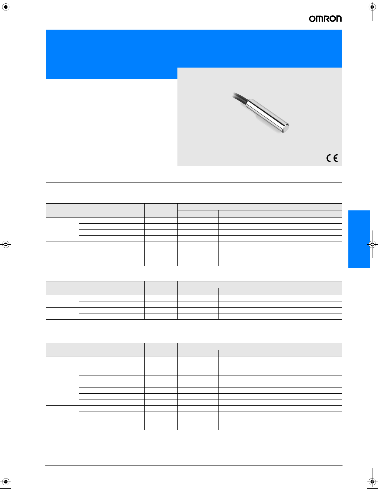
Omron E2EL User manual

D-99E2EL
E2EL
High Frequency Inductive Proximity Sensor
E2EL
Increased response
frequency for high speed
applications
• Max 5 kHz, switching frequency
• M8 or dia
• 6.5 mm housing
• Brass or stainless steel housing
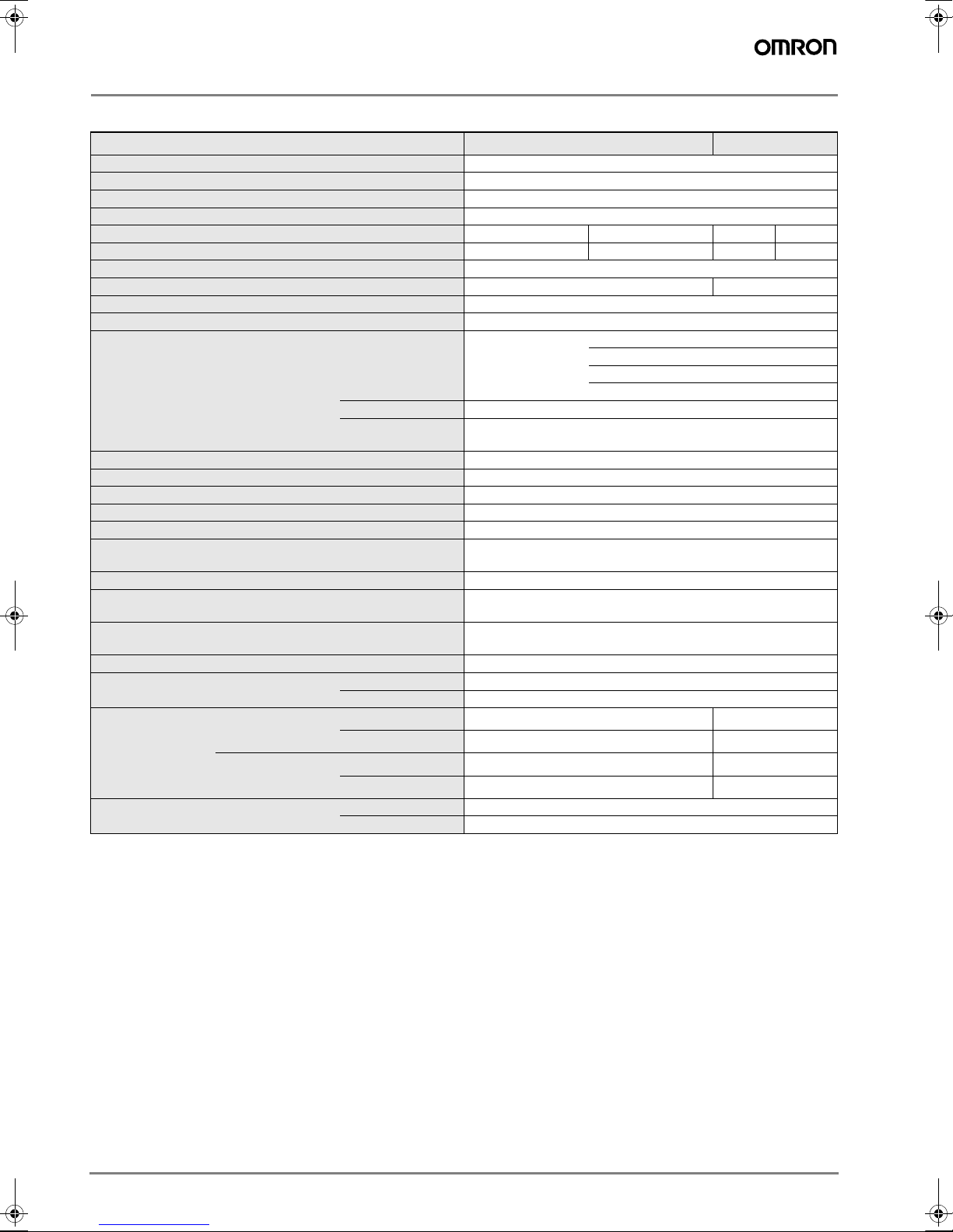
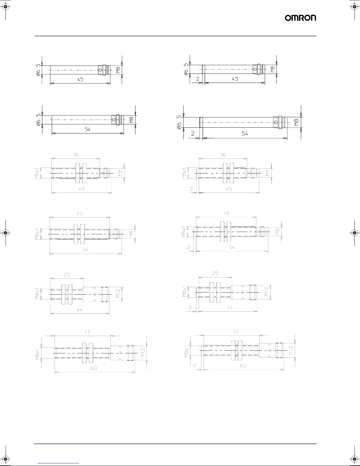
Ordering Information
Cable types
Brass housing
Stainless steel housing
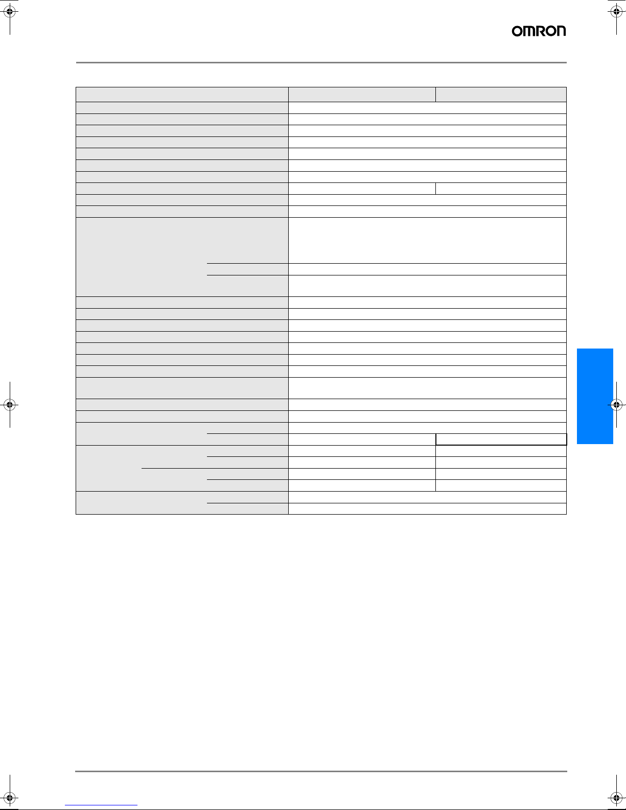
Plug types
Brass housing
Diameter Length Mounting Sensing
Distance
Output
NPN / NO NPN / NC PNP / NO PNP / NC
Ø6,5
30 mm Shielded 1,5 mm E2EL-C1R5E1 2M E2EL-C1R5E2 2M E2EL-C1R5F1 2M E2EL-C1R5F2 2M
32 mm Non-shielded 2,0 mm E2EL-C2ME1 2M E2EL-C2ME2 2M E2EL-C2MF1 2M E2EL-C2MF2 2M
45 mm Shielded 1,5 mm E2EL-C1R5E1-L 2M E2EL-C1R5E2-L 2M E2EL-C1R5F1-L 2M E2EL-C1R5F2-L 2M
47 mm Non-shielded 2,0 mm E2EL-C2ME1-L 2M E2EL-C2ME2-L 2M E2EL-C2MF1-L 2M E2EL-C2MF2-L 2M
M8
30 mm Shielded 1,5 mm E2EL-X1R5E1 2M E2EL-X1R5E2 2M E2EL-X1R5F1 2M E2EL-X1R5F2 2M
32 mm Non-shielded 2,0 mm E2EL-X2ME1 2M E2EL-X2ME2 2M E2EL-X2MF1 2M E2EL-X2MF2 2M
45 mm Shielded 1,5 mm E2EL-X1R5E1-L 2M E2EL-X1R5E2-L 2M E2EL-X1R5F1-L 2M E2EL-X1R5F2-L 2M
47 mm Non-shielded 2,0 mm E2EL-X2ME1-L 2M E2EL-X2ME2-L 2M E2EL-X2MF1-L 2M E2EL-X2MF2-L 2M
Diameter Length Mounting Sensing
Distance
Output
NPN / NO NPN / NC PNP / NO PNP / NC
Ø6,5 30 mm Shielded 2,0 mm E2EL-C2E1-DS 2M E2EL-C2E2-DS 2M E2EL-C2F1-DS 2M E2EL-C2F2-DS 2M
45 mm Shielded 2,0 mm E2EL-C2E1-DSL 2M E2EL-C2E2-DSL 2M E2EL-C2F1-DSL 2M E2EL-C2F2-DSL 2M
M8 30 mm Shielded 2,0 mm E2EL-X2E1-DS 2M E2EL-X2E2-DS 2M E2EL-X2F1-DS 2M E2EL-X2F2-DS 2M
45 mm Shielded 2,0 mm E2EL-X2E1-DSL 2M E2EL-X2E2-DSL 2M E2EL-X2F1-DSL 2M E2EL-X2F2-DSL 2M
Diameter Length Mounting Sensing
Distance
Output
NPN / NO NPN / NC PNP / NO PNP / NC
Ø6,5 /
Plug M8
45 mm Shielded 1,5 mm E2EL-C1R5E1-M3 E2EL-C1R5E2-M3 E2EL-C1R5F1-M3 E2EL-C1R5F2-M3
47 mm Non-shielded 2,0 mm E2EL-C2ME1-M3 E2EL-C2ME2-M3 E2EL-C2MF1-M3 E2EL-C2MF2-M3
54 mm Shielded 1,5 mm E2EL-C1R5E1-M3L E2EL-C1R5E2-M3L E2EL-C1R5F1-M3L E2EL-C1R5F2-M3L
56 mm Non-shielded 2,0 mm E2EL-C2ME1-M3L E2EL-C2ME2-M3L E2EL-C2MF1-M3L E2EL-C2MF2-M3L
M8 /
Plug M8
45 mm Shielded 1,5 mm E2EL-X1R5E1-M3 E2EL-X1R5E2-M3 E2EL-X1R5F1-M3 E2EL-X1R5F2-M3
47 mm Non-shielded 2,0 mm E2EL-X2ME1-M3 E2EL-X2ME2-M3 E2EL-X2MF1-M3 E2EL-X2MF2-M3
54 mm Shielded 1,5 mm E2EL-X1R5E1-M3L E2EL-X1R5E2-M3L E2EL-X1R5F1-M3L E2EL-X1R5F2-M3L
56 mm Non-shielded 2,0 mm E2EL-X2ME1-M3L E2EL-X2ME2-M3L E2EL-X2MF1-M3L E2EL-X2MF2-M3L
M8 /
Plug M12
44 mm Shielded 1,5 mm E2EL-X1R5E1-M1 E2EL-X1R5E2-M1 E2EL-X1R5F1-M1 E2EL-X1R5F2-M1
46 mm Non-shielded 2,0 mm E2EL-X2ME1-M1 E2EL-X2ME2-M1 E2EL-X2MF1-M1 E2EL-X2MF2-M1
60 mm Shielded 1,5 mm E2EL-X1R5E1-M1L E2EL-X1R5E2-M1L E2EL-X1R5F1-M1L E2EL-X1R5F2-M1L
62 mm Non-shielded 2,0 mm E2EL-X2ME1-M1L E2EL-X2ME2-M1L E2EL-X2MF1-M1L E2EL-X2MF2-M1L
F502-EN2-04.book Seite 99 Dienstag, 26. Juli 2005 5:48 17

D-100 Inductive Sensors
Specifications
Brass type
Type Ø6,5 M8
Operating voltage 10 to 35 VDC
Rated supply voltage 24 VDC
Current consumption max. 15 mA at 24 VDC
Sensing object Ferrous metals
Mounting ((s)hielded, (n)on-shielded) *1
*1. For detailed mounting instruction please refer to page D-105
snsn
Operating distance in mm 1,5 2,0 1,5 2,0
Tolerance of operating distance ±10%
Standard target size in mm (L x W x H in mm, FE 37) 6,5x6,5x1 8x8x1
Differential travel 1 % ... 15 % of operating distance
Max. response frequency in kHz 5,0
Control output
Type
E2EL-... E1 type: NPN-NO
E2 type: NPN-NC
F1 type: PNP-NO
F2 type: PNP-NC
Max-Load 200 mA
Max-on-state
Voltage drop
2,5 VDC (at 200mA load current and with 2 m cable)
Circuit protection Reverse polarity, output short-circuit
Indicator Operating indicator (yellow LED)
Ambient temperature Operating: -25° to 70°C
Humidity 35 to 95 % RH
Influence of temperature ± 10 % max. of Sn at 23°C in temperature range of -25° to 70°C
Dielectric strength 1.500 VAC, 50/60 Hz for 1 min. between current carry parts and
case
Electromagnetic compatibility EMC EN 60947-5-2
Vibration resistance Destruction: 10 to 70 Hz, 1,5 mm double amplitude for 1 hour each
in X, Y and Z directions
Shock resistance Destruction: 300 m/s² (approx. 30 G) for 6 times each in X, Y and Z
directions
Enclosure rating IP 67 (EN 60947-1)
Connection *2
*2. PUR cable and different length on request.
Pre-wired 2 m PVC-cable, 3 x 0,14 mm²
Connector M8 plug
Weight in g
Pre-wired long 45 50
short 43 48
Connector long 10 15
short 8 13
Material Case Brass
Sensing face PBTP
F502-EN2-04.book Seite 100 Dienstag, 26. Juli 2005 5:48 17

D-101E2EL
E2EL
Stainless steel type
Type Ø6,5 M8
Operating voltage 10 to 35 VDC
Rated supply voltage 24 VDC
Current consumption max. 15 mA at 24 VDC
Sensing object Ferrous metals
Mounting *1
*1. For detailed mounting instruction please refer to page D-105
shielded
Operating distance in mm 2,0
Tolerance of operating distance ±10%
Standard target size in mm (L x W x H in mm, FE 37) 6,5x6,5x1 8x8x1
Differential travel 1 % ... 15 % of operating distance
Max. response frequency in kHz 4,0
Control output
Type
E2EL-... E1 type: NPN-NO
E2 type: NPN-NC
F1 type: PNP-NO
F2 type: PNP-NC
Max-Load 200 mA
Max-on-state
Voltage drop
2,5 VDC (at 200mA load current and with 2 m cable)
Circuit protection Reverse polarity, output short-circuit
Indicator Operating indicator (yellow LED)
Ambient temperature Operating: -25° to 70°C
Humidity 35 to 95 % RH
Influence of temperature ± 10 % max. of Sn at 23°C in temperature range of -25° to 70°C
Dielectric strength 1.500 VAC, 50/60 Hz for 1 min. between current carry parts and case
Electromagnetic compatibility EMC EN 60947-5-2
Vibration resistance Destruction: 10 to 70 Hz, 1,5 mm double amplitude for 1 hour each in X, Y
and Z directions
Shock resistance Destruction: 300 m/s² (approx. 30 G) for 6 times each in X, Y and Z directions
Enclosure rating IP 67 (EN 60947-1)
Connection *2
*2. PUR cable and different length on request.
Pre-wired 2 m PVC-cable, 3 x 0,14 mm²
Connector - M8 plug
Weight in g
Pre-wired long 45 50
short 43 48
Connector long - 10
short - -
Material Case stainless steel 1.4305 / AISI 303
Sensing face PBTP
F502-EN2-04.book Seite 101 Dienstag, 26. Juli 2005 5:48 17

D-102 Inductive Sensors
Engineering data
Standardized characteristic for lateral approach
Output Circuit Diagram and Timing Chart
Pin Arrangement at Connector Types
0
0,2
0,4
0,6
0,8
1
1,2
-1 -0,8 -0,6 -0,4 -0,2 0 0,2 0,4 0,6 0,8 1
lateral distance related to radius of 'active surface' (r/ract)
standard target
axial
approach
lateral approach
off
'switch-on' curve
'switch-off' curve
axial distance related to effective operating distance
(s/s
r)
on
E2EL-@E@
NPN Output E2EL-@F@
PNP Output
Main
circuit
Brown 1
Blue 3
Load
Black 4 (or 2)
Blue 3
Load
Black 4 (or 2)
Brown 1
0 V
Main
circuit
4,7 kW
4,7 kW
Sensing object
Yellow indicator
Control output
Yes
No
ON
OFF
Lit
Not lit
NO NC
E2EL-@E@
NPN Output
Sensing object
Yellow indicator
Control output
Yes
No
ON
OFF
Lit
Not lit
NO NC
E2EL-@F@
PNP Output
1. Connector M8 (viewed to plug pins)
Output
+-
2. Connector M12 (viewed to plug pins)
2 free
NO
1 (+)
3 (-) 4 Output
2 Output
NC
1 (+)
3 (-) 4 free
F502-EN2-04.book Seite 102 Dienstag, 26. Juli 2005 5:48 17

D-103E2EL
E2EL
Dimensions
Cable types
E2EL-C1@R5 2M, E2EL-C2@-DS 2M E2EL-C2M@2M
E2EL-C1R5@-L 2M, E2EL-C2@-DSL 2M E2EL-C2M@-L 2M
E2EL–X1R5@2M, E2EL–X2@–DS 2M E2EL–X2M @2M
E2EL–X1R5@–L 2M, E2EL–X2 @–DSL 2M E2EL–X2M@–L 2M
F502-EN2-04.book Seite 103 Dienstag, 26. Juli 2005 5:48 17

D-104 Inductive Sensors
Plug types
E2EL-C1R5@-M3 E2EL-C2M@-M3
E2EL-C1R5@-M3L E2EL-C2M@-M3L
E2EL–X1R5@–M3 E2EL–X2M@–M3
E2EL–X1R5@–M3L, E2EL–X2 @DM3S E2EL–X2M @–M3L
E2EL–X1R5@–M1 E2EL–X2M@–M1
E2EL–X1R5@–M1L E2EL–X2M@–M1L
F502-EN2-04.book Seite 104 Dienstag, 26. Juli 2005 5:48 17

D-105E2EL
E2EL
Installation
Caution
Correct Use
Installation
Power Reset Time
The Proximity Sensor is ready to operate within 100 ms after
power is supplied. If power supplies are connected to the Proxim-
ity Sensor and load respectively, be sure to supply power to the
Proximity Sensor before supplying power to the load.
Power OFF
The Proximity Sensor may output a pulse signal when it is turned
off. Therefore, it is recommended to turn off the load before turn-
ing off the Proximity Sensor.
Power Supply Transformer
When using a DC power supply, make sure that the DC power
supply has an insulated transformer. Do not use a DC power sup-
ply with an auto-transformer.
Sensing Object
Metal Coating:
The sensing distance of the Proximity Sensor vary with the metal
coating on sensing objects.
Wiring
High-tension Lines
Wiring through Metal Conduit
If there is a power or high-tension line near the cord of the Prox-
imity Sensor, wire the cord through an independent metal conduit
to prevent against Proximity Sensor damage or malfunctioning.
Core Tractive Force
Do not pull cords with the tractive force exceeding the following:
pull force (N) = 20 x cable diameter ( mm)
Mounting
The Proximity Sensor must not be subjected to excessive shock
with a ha mmer when it is installed, otherwise the Proximity Sen-
sor may be damaged or lose the water-resistivity.
Environment
Water-Resistivity
Do not use the Proximity Sensor underwater, outdoors or in the
rain.
Operating Environment
Be sure to use the Proximity Sensor within operating ambient
temperature range and do not use the Proximity Sensor outdoors
so that its reliability and life expectancy can be maintained. Al-
though the Proximity Sensor is water resistive, a cover to protect
the Proximity Sensor from water or soluble machining oil is reco
mmended so that its reliability and life expectancy can be main-
tained. Do not use the Proximity Sensor in an environment with
chemical gas (e. G., strong alkaline or acid gases including nitric,
chromic, and concentrated sulfuric acid gases).
Item Examples
Power Supply
Do not impose an excessive voltage on the E2EL, otherwise it may
explode or burn.
Do not impose 24 VAC on any E2EL model, otherwise it may ex-
plode or burn.
Load short-circuit
Do not short-circuit the load, or the E2EL may explode or burn.
The E2EL's short-circuit protection function is valid, if the polarity of
the supply voltage imposed is incorrect and within the rated voltage
range.
Wiring
Be sure to wire the E2EL and load correctly, otherwise it may ex-
plode or burn.
F502-EN2-04.book Seite 105 Dienstag, 26. Juli 2005 5:48 17

D-106 Inductive Sensors
Effects of Surrounding Metal
Shielded types:
Shielded types allow direct installation on metal plates in an em-
bedded manner without performance change. A minimum dis-
tance of 3sn is required between the active surface and a metallic
surface in front of the device. (Fig. 1).
For SUS shielded types the following minimum distances are re-
quired to avoid performance change (see Fig.2 and table below):
Fig.1: Shielded type (except SUS)
Fig.2: Shielded SUS type
Non-shielded types:
Installation of non-shielded types in metal require the minimum
distances according to Fig. 3.
Fig.3: Non-shielded type
Item Examples Item
AND (serial connection) The Sensors connected together must satisfy the
following conditions:
iL + (N-1) x i = Upper-limit of control output of each
Sensor
VS - N x VR = Load operating voltage
N = No. of Sensors
VR = Residual voltage of each Sensor
VS = Supply voltage
i = Current consumption of the Sensor
iL = Load current
If the MY Relay, which operate at 24 VDC, is used as a
load for example, a maximum of two Proximity Sensors
can be connected to the load.
OR (parallel connection) The number of Sensors connected in parallel varies
with the Proximity Sensor model.
Shielded SUS Types Free zone
E2EL-2@-DS 0,5 mm
≥3sn
≥3sn
Freezone
d
≥3sn≥2sn
≥3d
In the interest of product improvement, specifications are subject to change without notice.
ALL DIMENSIONS SHOWN ARE IN MILLIMETERS.
To convert millimeters into inches, multiply by 0.03937. To convert grams into ounces, multiply by 0.03527.
Cat. No. D06E-EN-01
F502-EN2-04.book Seite 106 Dienstag, 26. Juli 2005 5:48 17
Table of contents
Other Omron Accessories manuals

Omron
Omron D6F-PH User manual

Omron
Omron ZFV-CA50 User manual

Omron
Omron F3S-TGR-SB-K C User manual

Omron
Omron D6T Series User manual

Omron
Omron E3F2-Z User manual

Omron
Omron ZFV - V2.0 User manual

Omron
Omron E2CY User manual

Omron
Omron E3X-DA-S Series User manual

Omron
Omron ZS Series Installation manual

Omron
Omron F3W-D User manual

Omron
Omron ZW-S7010 Operating instructions

Omron
Omron E3ZS User manual

Omron
Omron XPECTIA FZ3 User manual

Omron
Omron E3M-V - User manual

Omron
Omron F160 Vision Sensor User manual

Omron
Omron V680-HAM91 User manual

Omron
Omron E2 ELITE User manual

Omron
Omron FQ-AC Series User manual

Omron
Omron F3SG-PG Series Operating and maintenance instructions

Omron
Omron ZS-L - User manual