Communication Interface Specifications
2
ZFX-C Serial Communication Command Reference
Communication Interface Specifications
You can use the USB port or RS-232C/422 connector of the Controller to perform serial communication with
external devices such as a personal computer or programmable controller.
Serial communication functions in the RUN mode. Communication cannot be performed in the ADJ or MENU
modes.
<USB>
This interface allows Full speed (12 Mbps) communications compliant with USB2.0 with a PC equipped with
the same USB interface.
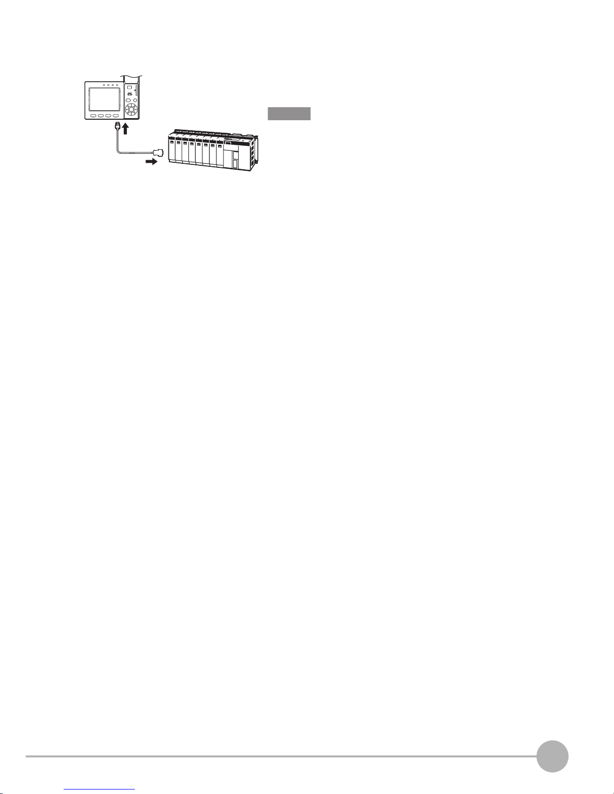
<RS-232C/422>
This interface allows data communications compliant with the EIA RS-232C/422 standards up to a maximum
speed of 115200 bps.
For details on how to set the communication specifications, refer to the User's Manual.
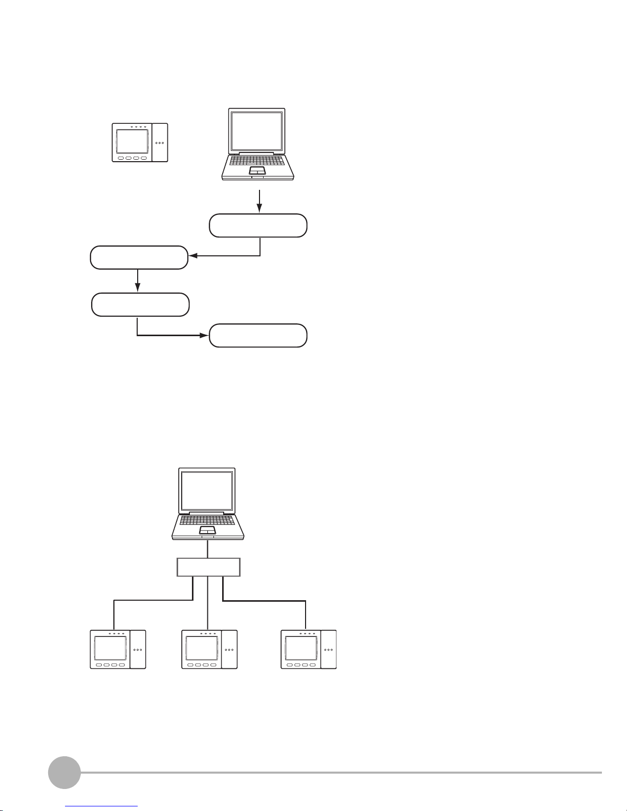
<Ethernet>
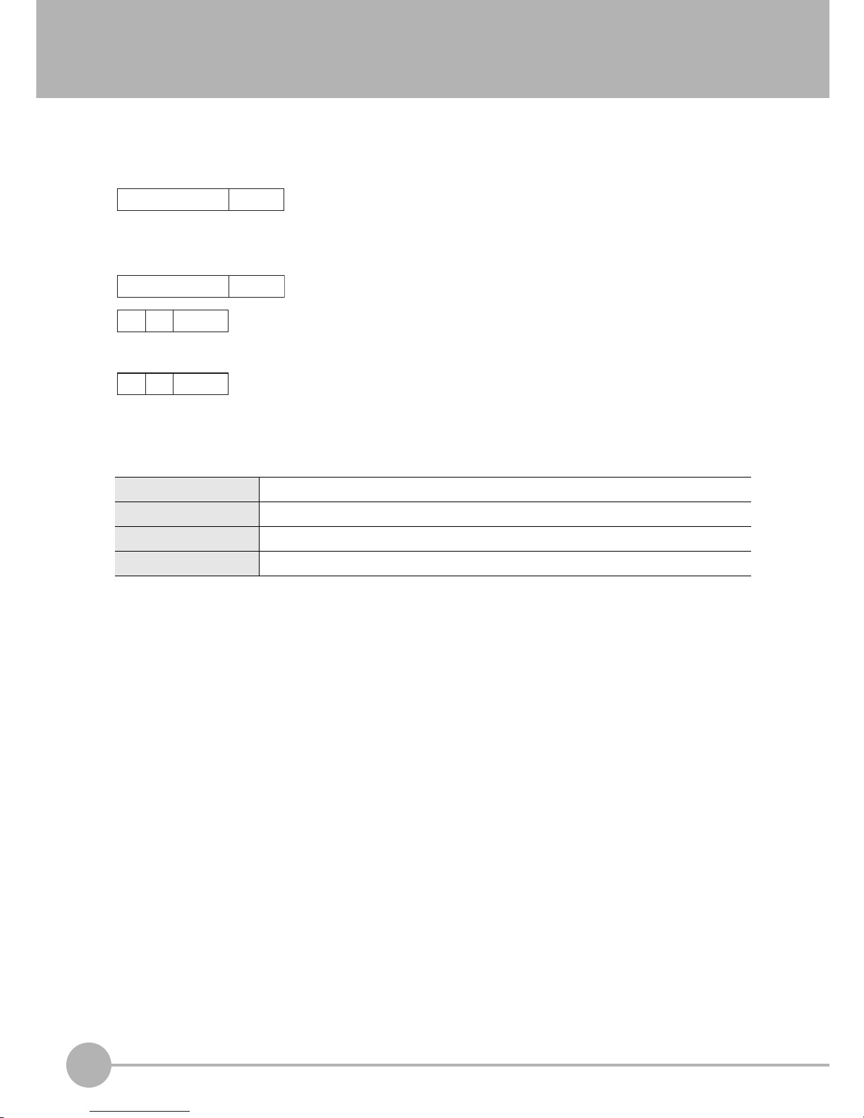
Synchronization method Start-stop
Transmission code ASCII (Binary format can be selected only when outputting measurement values set at
[Setup] - [Support] - [Calculation] - [Data].)
Communication speed USB2.0-compliant
Data length -
Parity -
Stop bit -
Delimiter CR, LF, CR+LF
Transmission protocol Normal (Note, however, that XMODEM protocol is used when sending image data, system
data and other data.)
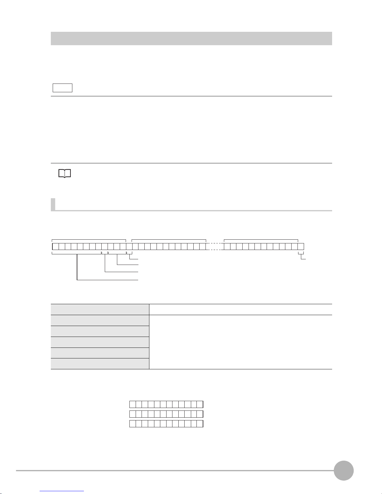
Synchronization method Start-stop
Transmission code ASCII (Binary format can be selected only when outputting measurement values set at
[Setup] - [Support] - [Calculation] - [Data].)
Communication speed 9600, 19200, 38400, 57600, 115200
Data length 7 bits, 8 bits
Parity None, even, odd
Stop bit 1 bit, 2 bits
Delimiter CR, LF, CR+LF
Transmission protocol Normal (Note, however, that XMODEM protocol is used when sending image data, system
data and other data.)
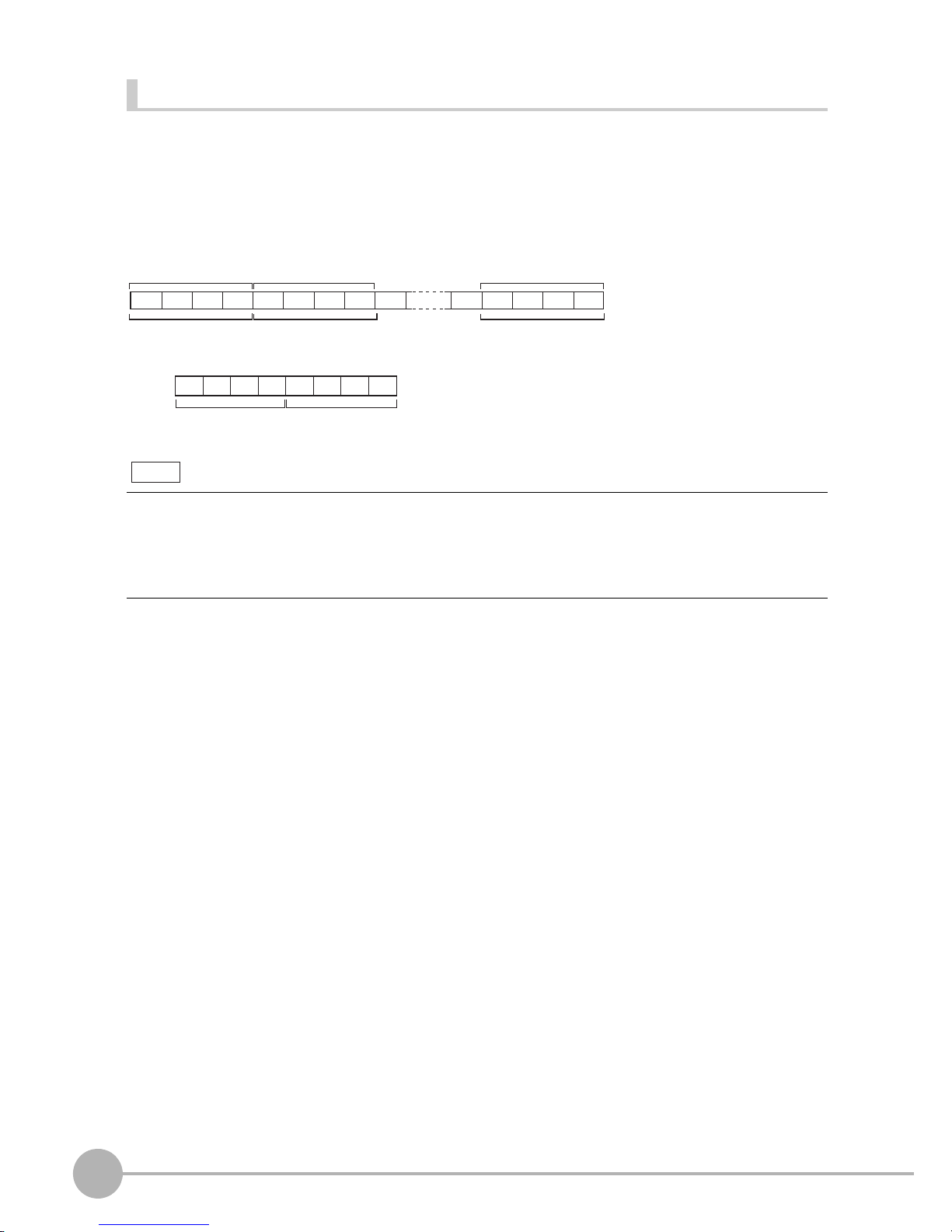
Communication protocol TCP/IP
Transmission mode Peer to Peer