Startup Display and Display Elements
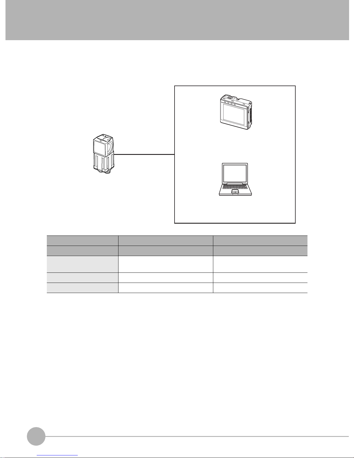
FQ Short Manual 7
1 Introduction
Display Elements
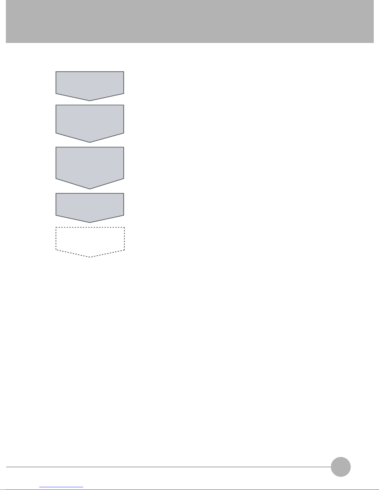
This Sensor has a Setup Mode and a Run Mode.
Setup Mode
In Setup Mode, you can set the image conditions, judgement parameters, and I/O settings for the Sensor.
Run Mode
In Run Mode, measurements are performed, and measurement results are output.
p. 53
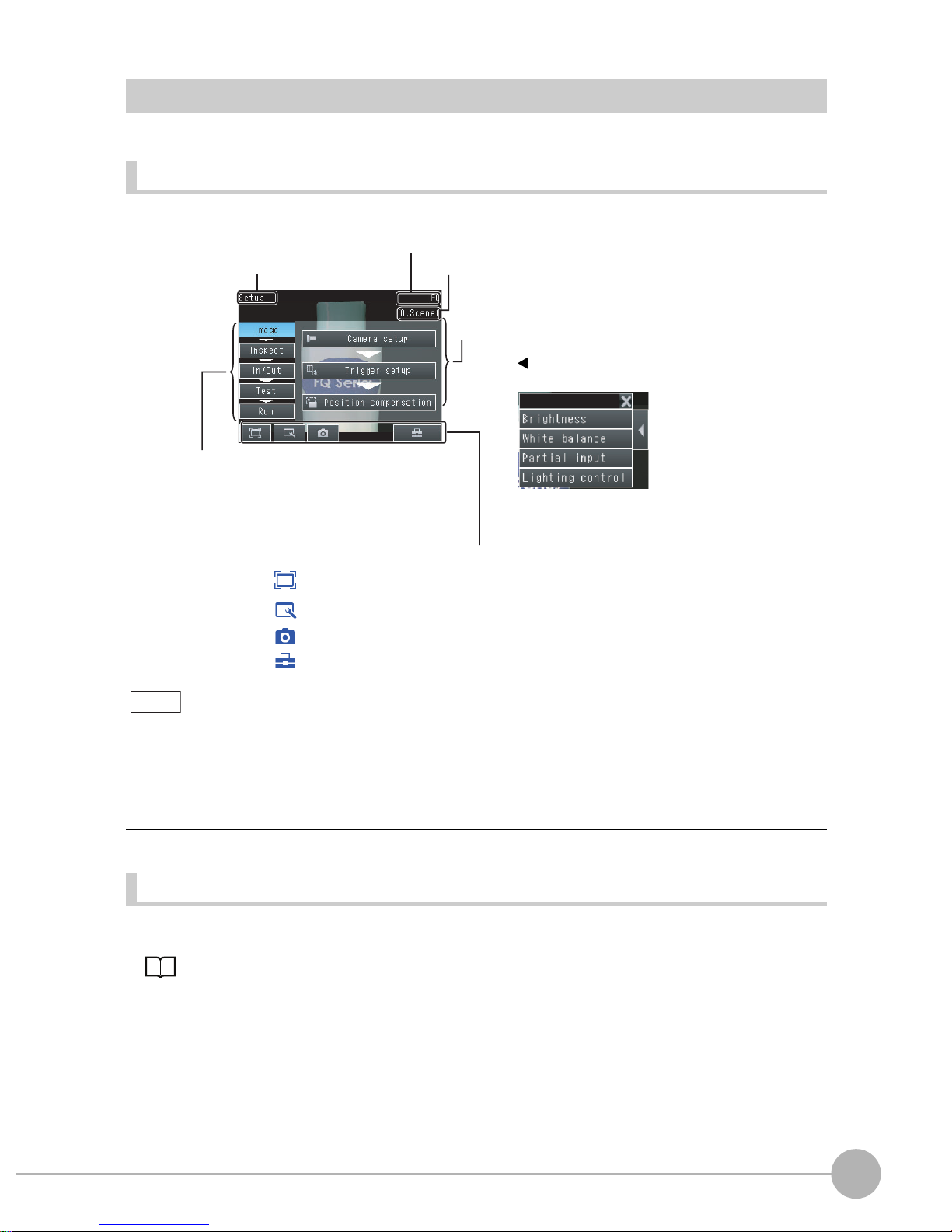
The Display Button can be used to switch between the following images.
• Live: The live image is displayed.
• Freeze: The image that was taken last is displayed.
• Log: An image saved in internal memory is displayed.
• File: An image saved on an SD card is displayed.
Tool Button: Used to call functions, such as saving data or select scenes.
Capture Button: Used to capture the current screen to the SD card.
This button menu is always displayed.
[Image]: Used to adjust the image.
[In/Out]: Used to set the I/O.
[Run]: Used to switch to Run Mode.
[Test]: Used to test and adjust the set measurements.
[Inspect]: Used to set the inspection items.
The setup flow is shown by these five tabs.
•If the [ ] Button appears, pressing it will display the
sub-menu or commands.
•Buttons will appear on the right according to the mode.
The menu changes according to the selected tab page.
The selected scene number is displayed.
The name of the Sensor being set up is displayed.
Only-image Button: Used to select either displaying the camera image and messages, or
only the camera image.
Display Button: Used to select the source of the image or to zoom the image.
The name of the mode or the
menu hierarchy is displayed.
Note