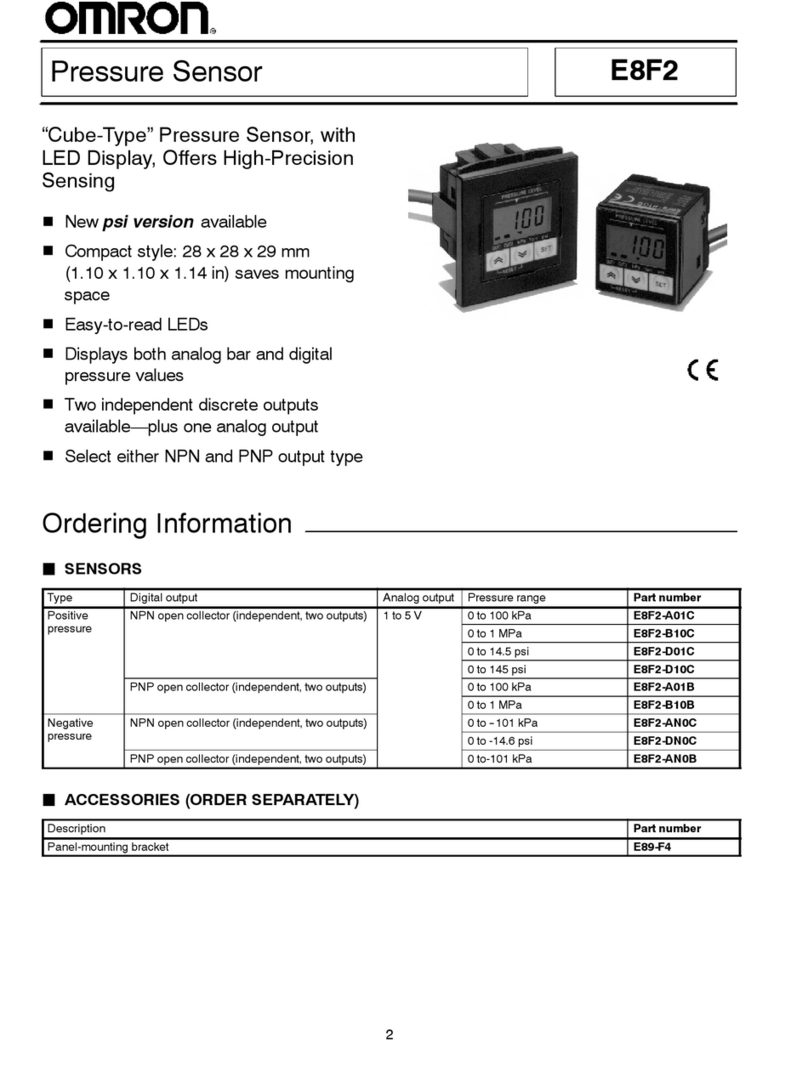
E8F2 E8F2
6
Function/Setting PageDescription
ON/OFF set value check function Checks the set ON and OFF points. 16
Settings
Digital Display
The E8F2 displays alphanumeric characters, such as measure-
ment
values and menu items, with 7-segment LEDs as shown
be
-
low
for example.
Display Meaning
ope
In output ope
ration
kpa Unit (kPa)
wid Width
The following abbreviations are used for the digital display of the
Controller.
Abbreviation Meaning Abbreviation Meaning
Unt Unit DSP Display
M-A Manual/Auto AVE Average
OPE Operation BAR Bar
PRT Protect AUT Auto
HYS Hysteresis ECO Economy
WID Width
a b c d e f g h i j k l m n o p r s t u U w x y =
A B C D E F G H I J K L M N O P Q R S T U V W X Y Z
Modes
In
addition to displaying measurement values, the E8F2 has a variety of functions. These functions are
available in four main modes as de
-
scribed
below
. Three functions are available in measurement mode. For the relationships among each mode and for switching methods, refer
to
the following figure.
Power ON
Zero-reset function
ON- and OFF-point check
function
No key operation
No key operation
Measurement
mode
Energy-saving function 1
Energy-saving function 2
or or
Basic Setting Mode
unt:
Measurement unit selection
mĆa
: Pressure setting method
selection
ope: Output-type selection
Pressure Setting Mode
on: OUT1 ON-point setting
off: OUT1 OFF-point setting
Manual setting
on: OUT2 ON-point setting
off: OUT2 OFF-point setting
t.h1:
OUT1 two-point teaching
t.w
: OUT1 one-point teaching
Auto-teaching setting
t.h1:
OUT2 two-point teaching
t.w
: OUT2 one-point teaching
prt: Key-protect setting
Special Setting Mode
hys: Hysteresis width setting
wid: Window width setting
dsp: Measurement value display
refresh interval setting
aUe
: Number of measurement times
setting for measurement value averaging
bar
: LED bar indicator range setting
or
or
Note: 1.
and
indicate that the key must be pressed for approximately 2 or 3 s respectively
.
2.
The following will result when the E8F2 in basic, pressure setting, or special setting mode is reset to measurement mode.
:
The set values are entered.
:
The set values are not entered (left as they are).
