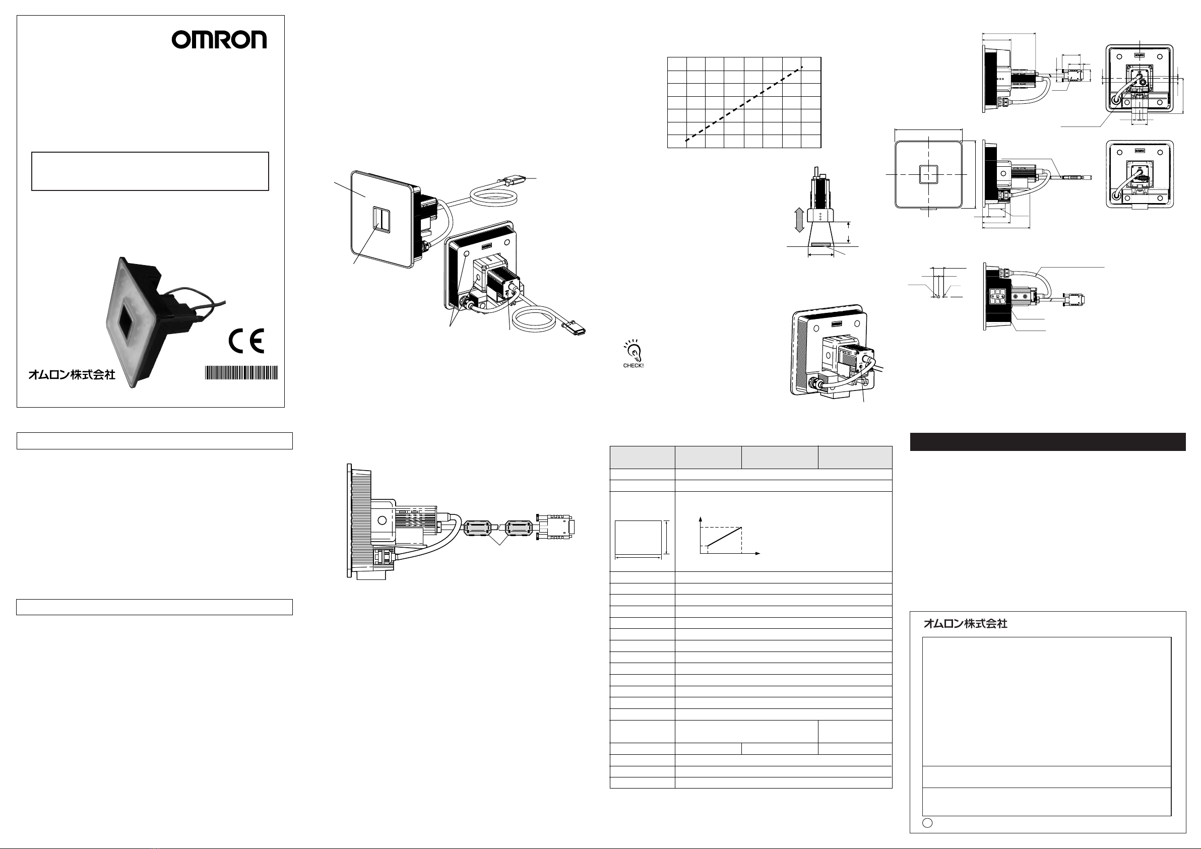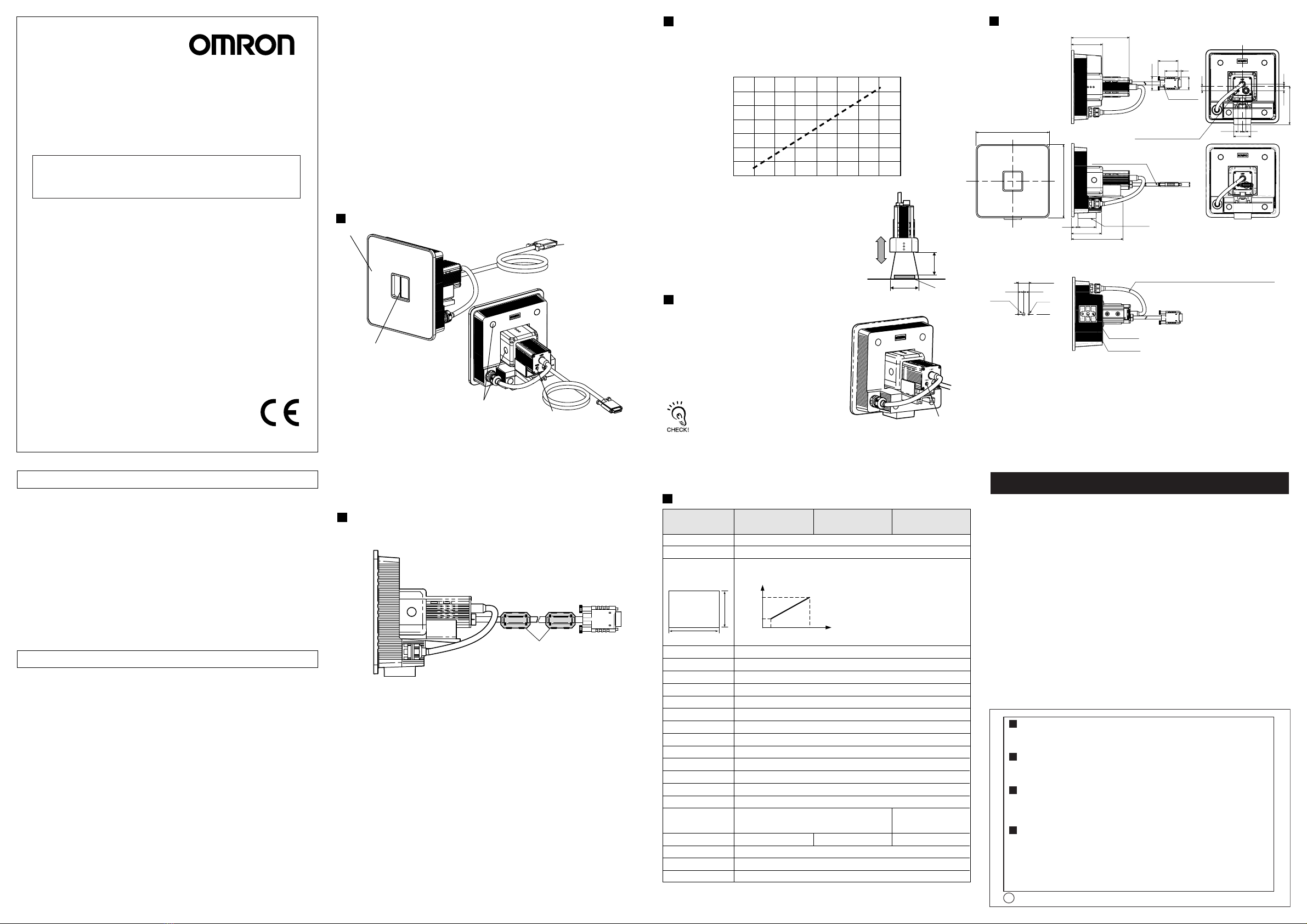
(1) Lighting part
This section emits light.
(2) Receiver part
This section captures the
image.
(3) Connector
This connector is connected
to the Amplifier Unit.
(4) Focus adjustment control
This control is used for adjusting the focus of the image.
(5) Ventilation film
This film prevents the front panel from condensation.
PRECAUTIONS FOR SAFE USE
PRECAUTIONS FOR CORRECT USE
Please observe the following precautions to prevent failure to operate, malfunctions,
or undesirable effects on product performance.
Do not install the product in locations subjected to the following conditions.
・Ambient temperature outside the rating
・Rapid temperature fluctuations (causing condensation)
・Relative humidity outside the range of 35 to 85%
・Presence of corrosive or flammable gases
・Presence of dust, salt, or iron particles
・Direct vibration or shock
・Reflection of intense light (such as other laser beams , electric arc welding machines
or ultraviolet rays)
・Direct sunlight or near heaters
・Water, oil, or chemical fumes or spray
・Strong magnetic or electric field
(1) Installation Site
The center of the optical axis sometimes differs according to each Sensor Head.
During installation, be sure to check the center of the image and the detection range
on the LCD monitor of the Amplifier Unit.
(3) Optical Axis and Detection Range
Please observe the following precautions for safe use of the products.
・Do not use thinner, benzene, acetone or kerosene to clean the Sensor Head and
Amplifier Unit.
・If large dust particles adhere to the front Panel of the Sensor Head, use a blower
brush (used to clean camera lenses) to blow them off. Do not blow off the dust
particles with your mouth.
・To remove smaller dust particles, wipe gently with a soft cloth.
Do not use excessive force to wipe off dust particles. Scratches on the front
Panel may cause errors.
(5) Maintenance and Inspection
227mm
115mm
89mm 148mm
Setting
distance
(L)
Detection
range
(H)
(1) Installation Environment
・Do not use the product in environments where it can be exposed to inflammable /
explosive gas.
・To secure the safety of operation and maintenance, do not install the product close
to high-voltage devices and power devices.
・During installation, make sure that screws are tightened firmly.
(3) Others
・Do not attempt to dismantle, repair, or modify the product.
・Dispose of this product as industrial waste.
・If abnormal odors, heating, or smoke occurs, stop using the Smart Sensor
immediately, turn OFF the power, and consult with your OMRON representative.
(2) Power Supply and Wiring
・High-voltage lines and power lines must be wired separately from this product.
Wiring them together or placing them in the same duct may cause induction,
resulting in malfunction or damage.
(2) Power Supply and Wiring
・Do not peel off or probe the ventilation film with a sharp-pointed object.
If you so, the specifications of the protective structure may no longer be satisfied.
・Do not block the ventilation film. Doing so might cause the front panel to be
con-densed.
(4) Ventilation Film
Part Names and Functions
Specifications
Dimensions
Model ZFX-SC150
□
Smart Sensor
For Model ZFX-C□□
Sensor head unit
・Before connecting/disconnecting the Sensor Head, make sure that the Smart Sensor
is turned OFF. The Smart Sensor may break down if the Sensor Head is connected
or disconnected while the power is ON.
・Use only combinations of Sensor Heads and Sensor Controllers specified in this
sheet.
(Unit : mm)
Item
Setting distance (L)
Detection range (H V)
Relation between setting
distance and detection range
Object lighting method
Object light source
Extra light interface
Sensing element
Shutter
Power supply voltage
Current consumption
Dielectric strength
Vibration resistance (destruction)
Shock resistance (destruction)
Ambient temperature
Ambient humidity
Ambient atmosphere
Connection method
115 to 227 mm
89×89 mm to 148×148 mm
Pulse lighting
Seventy two white LEDs
Not available
1/3-inch interline color CCD (reading all pixels)
Electronic shutter, shutter time: 1/170 to 1/20,000s
15 VDC, 48 VDC (Supplied from Amplifier Unit.)
Approx. 350 mA[15VDC:Approx. 150 mA, 48VDC:Approx. 200 mA]
1,000 VAC, 50/60 Hz for 1 min
10 to 150 Hz, 0.35-mm single amplitude, 10 times each in X, Y, and Z directions for 8 min
150 m/s2, three times each in six directions (up/down, left/right, forward/backward)
Operating: 0 to 40 ℃, Storage: -20 to 65 ℃(with no icing or condensation)
Operating and storage: 35% to 85% (with no condensation)
Must be free of corrosive gas.
Detection
range V
H
© OMRON Corporation All Rights Reserved.
2007-2009
(1) Lighting part
(2) Receiver part
(3) Connector
(5) Ventilation film
(4) Focus adjustment
control
Attach the ferrite core (provided with the Smart Sensor) to the case side and the
connector side of the Sensor Head.
Attaching the ferrite core
Ferrite core
The following graphs show the relationship between detection range and setting
distance for each model of Sensor Head.
Values differ according to each model of Sensor Head, so fully check the model before
using these graphs.
(Example)
When using a ZFX-SC150 Sensor Head
at a detection range of 125 mm required
for the location of the sensing object, the
setting distance of Sensor Head becomes
180mm.
Detection range
H (mm)
Setting distance
L (mm)
(1) Install the Sensor Head at the installation
distance obtained in the above graphs.
(2) Turn the focus adjustment control
to the left and right to adjust the focus.
Workpiece
Installation distance
Installation procedure
Setting
distance L
Detection range H
Focus
adjustment
control
INSTRUCTION SHEET
Thank you for selecting OMRON product. This sheet pri-
marily describes precautions required in installing and
operating the product.
Before operating the product, read the sheet thoroughly to
acquire sufficient knowledge of the product. For your con-
venience, keep the sheet at your disposal.
OMRON Corporation
Suitability for Use
EUROPE
OMRON EUROPE B.V. Sensor Business Unit
Carl-Benz Str.4, D-71154 Nufringen Germany
Phone:49-7032-811-0 Fax: 49-7032-811-199
NORTH AMERICA
OMRON ELECTRONICS LLC
One Commerce Drive Schaumburg,IL 60173-5302 U.S.A.
Phone:1-847-843-7900 Fax : 1-847-843-7787
ASIA-PACIFIC
OMRON ASIA PACIFIC PTE. LTD.
No. 438A Alexandra Road #05-05-08(Lobby 2),
Alexandra Technopark, Singapore 119967
Phone : 65-6835-3011 Fax :65-6835-2711
o
THE PRODUCTS CONTAINED IN THIS SHEET ARE NOT SAFETY RATED.
THEY ARE NOT DESIGNED OR RATED FOR ENSURING SAFETY OF
PERSONS, AND SHOULD NOT BE RELIED UPON AS A SAFETY
COMPONENT OR PROTECTIVE DEVICE FOR SUCH PURPOSES.
Please refer to separate catalogs for OMRON's safety rated products.
OMRON shall not be responsible for conformity with any standards, codes, or
regulations that apply to the combination of the products in the customer's
application or use of the product.
Take all necessary steps to determine the suitability of the product for the
systems, machines, and equipment with which it will be used.
Know and observe all prohibitions of use applicable to this product.
NEVER USE THE PRODUCTS FOR AN APPLICATION INVOLVING
SERIOUS RISK TO LIFE OR PROPERTY WITHOUT ENSURING THAT THE
SYSTEM AS A WHOLE HAS BEEN DESIGNED TO ADDRESS THE RISKS,
AND THAT THE OMRON PRODUCT IS PROPERLY RATED AND
INSTALLED FOR THE INTENDED USE WITHIN THE OVERALL
EQUIPMENT OR SYSTEM.
See also Product catalog for Warranty and Limitation of Liability.
CHINA
OMRON(CHINA) CO., LTD.
Room 2211, Bank of China Tower,
200 Yin Cheng Zhong Road,
PuDong New Area, Shanghai, 200120, China
Phone : 86-21-5037-2222 Fax :86-21-5037-2200
OCT, 2009
Before tuning the focus adjustment control
slightly to the right, make sure that the guide
mark is not at the lower limit position.
The focus adjustment control is a multi-turn
control. However, the control stops turning at
the lower limit position (right turn).
The control turns idle even after the upper limit position (left turn).
Do not exert unnecessary force to turn the control at the upper or
lower limit positions as this might damage the control.
59.5
110.2
26.2
CONNECTOR
38.14
25.34 5.9
24.2
HEAT-RESISTANT VINYL CHLORIDE SHIELD CODE
6.2 Dia. STANDARD LENGTH 2m
MOUNTING
SURFACE
12 35
57
98
8
2-M4 DEPTH 6
U1/4-20UNC DEPTH 5
HEAT-RESISTANT・OIL-RESISTANT VINYL CHLORIDE SHIELD CODE
5 Dia. STANDARD LENGTH 200m
140
140
20±0.1
10 10
2-4.5Dia.
U1/4-20UNC
MOUNTIONG SCREW HOLES
33
8.5 7
4
8.5
73.2
8.5
FOCUS ADJUSTMENT VOLUME
100
180
240
80 120 160
Tighter mounting screws at the torque specified.
Recommended screw tightening torque
M4:1.2N・m,
1/4”-20UNC:2.6N・m
(6) Installation Precautions
NOTICE:
This product meets CISPR11 class A . The intended use of this product is in an
industrial environment only.
Case: ABS
Approx. 600 g (including cord)
Ferrite core (2), Instruction sheet
IEC60529, IP65 IEC60529, IP67
Prewired, Standard cable
length: 2 m
Degree of protection
Materials
Weight
Accessories
Prewired, Crooked-proof cable
length: 2 m
IEC60529, IP65
ZFX-SC150
(Ultra-wide View)
ZFX-SC150W
(Ultra-wide View)
ZFX-SC150R
(Ultra-wide View)
Manufacturer:
Omron Corporation,
Shiokoji Horikawa, Shimogyo-ku,
Kyoto 600-8530 JAPAN
Ayabe Factory
3-2 Narutani, Nakayama-cho,
Ayabe-shi, Kyoto 623-0105 JAPAN
TRACEABILITY INFORMATION:
Representative in EU:
Omron Europe B.V.
Wegalaan 67-69
2132 JD Hoofddorp,
The Netherlands