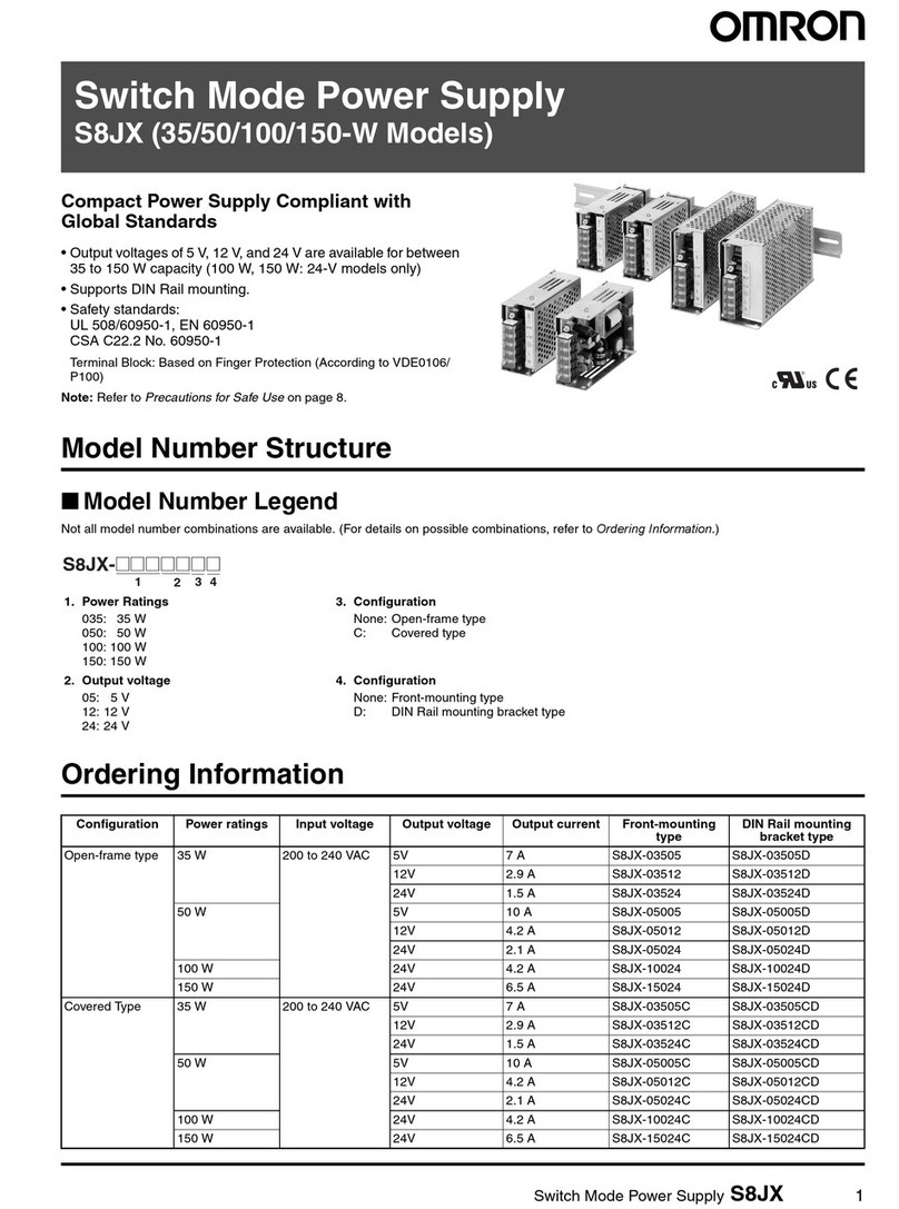
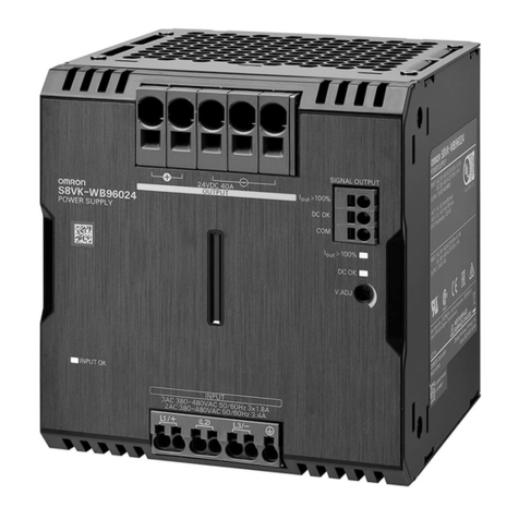
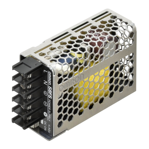
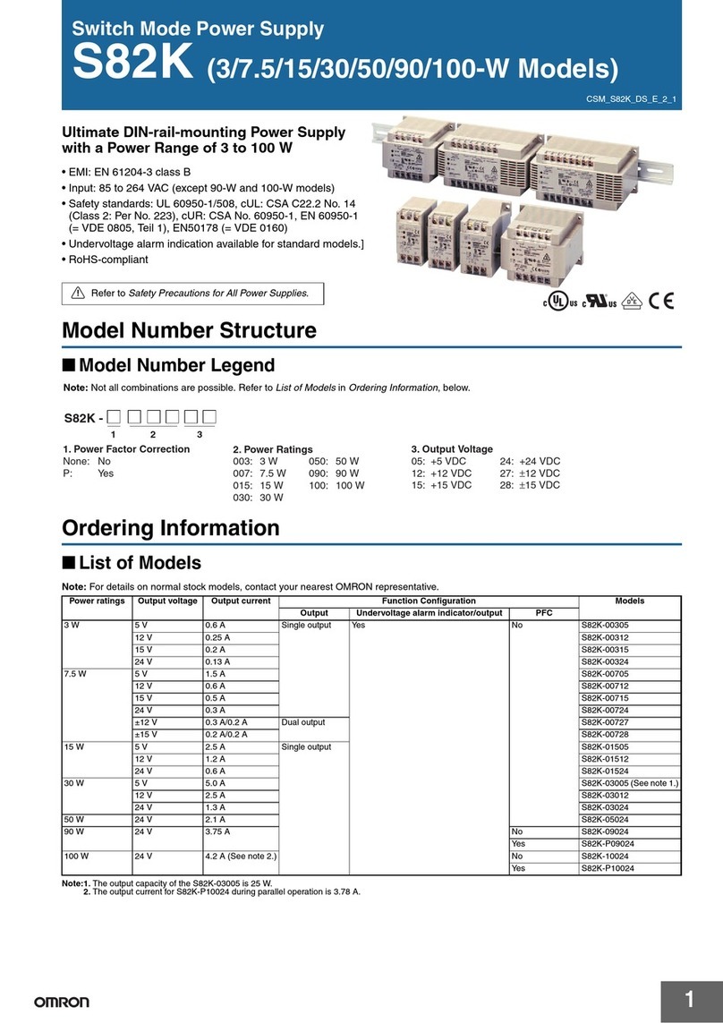
Omron S8T-DCBU-01 User manual

S8T-DCBU-01
Block Power Supply DC Backup Block
for Preventing 24 VDC Outages due to
Instantaneous Power Failures
■Supplies 24 VDC for a fixed period of time even
during AC input outages to considerably improve
system reliability.
■Block Power Supply Basic Block is connected by
the Bus Line Connector.
Simple system configuration.
■Alarms are notified by indication on main unit and
by alarm signal output.
Ordering Information
■DC Backup Block (See note 1.)
Note: 1. One S8T-BUS03 Connector is included as accessory.
2. The output current can be selected by a switch.
■Bus Line Connector
Note: One package contains 10 S8T-BUS03 Connectors.
■Battery Holder
■Basic Block
Note: Use S8T-BUS01 in a pair with the Block Power Supply Basic Block.
Block Power Supply Basic Block
DC Backup Block
Output voltage Output current Model
24 V 3.7 A / 8 A (See note 2.) S8T-DCBU-01
Type Number of Connectors Model
DC line bus 1 Connector S8T-BUS03
10 Connectors (See note.) S8T-BUS13
Model
S82Y-TS01
Type Output voltage/output current Model
Screw terminal type 24 V / 2.5 A S8TS-06024
Connector terminal type S8TS-06024F

2
S8T-DCBU-01 S8T-DCBU-01
Basic Configuration
■Maximum Number of S8TS-06024Block Power Supply Basic Blocks that
can be Linked / Specified Battery
Note: 1. Specified batteries are made by Matsushita Electric Industrial Co., Ltd. (Panasonic).
2. The rated voltage of the specified battery is 12 V. Use two specified batteries connected in series.
3. Be sure to connect the S8TS-06024Basic Block.
4. Consult your OMRON representative when purchasing batteries.
Battery Sales Area Japan
Overcurrent
protection function
selector switch
Maximum number of
S8TS-06024Basic Blocks
that can be linked
Specified
battery
LC-P122R2J LC-P123R4J
5.7 A (typical) 2 Blocks
(3 Blocks if N + 1 redundant system is used)
Yes Yes
11.7 A (typical) 4 Blocks
(5 Blocks if N + 1 redundant system is used)
—— Yes
S8T-BUS01
Bus Line Connector
(Order separately)
Connect to
Loads
Connect to
Batteries
Connect to
AC Lines
S8TS-06024
Block Power Supply Basic Block
(Order separately)
S8T-BUS03 Bus Line Connector
S8T-DCBU-01 DC Backup Block
S82Y-TS01 Battery Holder
(Order separately)
Note: One S8T-BUS03 Connector is included with the
S8T-DCBU-01 DC Backup Block.
Note: S8T-BUS01 Connector is used
for connecting to the
S8T-06024Basic Block.

3
S8T-DCBU-01 S8T-DCBU-01
Operation
Backup
The S8T-DCBU-01 detects drops in the output voltage of the
S8TS-06024and switches over to backup operation.
Backup operation is continued for about seven seconds even if the
output voltage of the S8TS-06024is reset.
Note: 1. If this state occurs, a probable cause is an S8TS-
06024overload or it is out of order. Immediately
eliminate the cause of the trouble.
2. Output voltage also fluctuates in keeping with repeated
alternate switching between backup operation and
regular operation.
3. The relay contact capacity is 24 VDC, 0.1 A.
4. If the load fluctuates suddenly, the output voltage of the
S8TS-06024sometimes drops resulting in backup
operation.
5. The maximum inrush current shown below flows when
backup operation is switched to.
Charging Circuit
Charging Time (Reference Values)
Note: The times shown in the table above are required for
charging the battery.
If a power failure occurs within the above charging times,
backup operation at the required time may not be
possible.
Output Voltage Setting of the S8TS-06024
The DC Backup Block detects drops (approx. 23 VDC) in the
output voltage of the connected S8TS-06024and switches over
to backup operation.
The output voltage of the S8TS-06024can be adjusted by the
output voltage adjustment trimmer. When using the S8TS-
06024connected to the DC Backup Block, do not set the voltage
to a value lower than the factory set voltage.
Length of Wires between S8T-DCBU-01 and
Battery
Limit the wire between the S8T-DCBU-01 and the battery to 1.5 m
or less using wires of gages indicated at "Recommended Wire
Size" on page 14.
As the battery voltage is monitored at Battery Connector terminal,
wiring longer than 1.5 m will cause a large impedance which Will
Result in a larger voltage drop on the wiring and a shorter backup
time.
S82Y-TS01 Battery Holder
We recommend using the S82Y-TS01 Battery Holder for
connecting and installing the battery. Take the following points
into consideration when using the S82Y-TS01:
(1) Contact between leaking battery fluid and metal parts having
an electric potential may cause smoke or fire. To prevent this,
place the battery on a resin battery tray.
(2) The inrush current shown below flows when backup operation
is switched to. The peak value and time of this inrush current
vary according to the capacity of the input capacitor of the
connected equipment, battery charge status, battery wiring
length, and ambient temperature. The switch and fuse of the
S82Y-TS01 are selected taking this inrush current into
consideration. When replacing the fuse, use only the specified
fuse. (Littelfuse, 257015 (15 A))
(3) In the event that the battery generates inflammable gases,
place the switch and fuse away from the convection path of the
inflammable gas to prevent the switch or fuse from causing
ignition and explosion.
(4) Storing the S8T-DCBU-01 still connected to the battery may
cause the battery to discharge and considerably reduce the
service life of the battery. To prevent this, turn the switch OFF.
Mounting and Removing Bus Line Connector
Pay attention to the following points to maintain electrical
characteristics.
• Do not insert/remove the Connectors more than 20 times.
• Do not touch the Connector terminals.
• To remove the Connectors, insert a flat-bladed screwdriver
alternately at both ends.
Backup
status
LED
(BACKUP: Red)
Relay
(OPN MODE)
Power failure
Backup
operation is
performed
continuously.
Lit Backup
(1)-(2): ON
One S8TS-
06024
Basic Block
is out of
order.
When one
S8TS-
06024
Basic Block
is used
When two or
more S8TS-
06024
Basic Blocks
are used
(See note 1.)
Regular
operation and
backup
operation are
repeated
alternately at
about 7-
second
cycles.
Flash at
about
7-second
cycles
Regular
operation ((3)-
(2): ON) and
backup
operation ((1)-
(2): ON) are
repeated
alternately at
about 7-
second cycles.
When the overcurrent
protection function of the
S8TS-06024is active
(See note 1.)
Battery used 100% charge 80% charge
LC-P122R2J 24 to 48 hours 5 hours
LC-P123R4J 8 hours
COM
Normal
Backup
LED lit
(BACKUP: Red)
Relay (OPN MODE)
(1)-(2): ON
Operation mode
output relay
Indicator
1
2
3
45
0Time
Battery charge status: Fully charged
Ambient temperature: 40˚C
Input capacitor of connected equipment: 56,000 µF
Load power: 192 W
25 ms
Inrush current (A)
45
0Time
Battery charge status: Fully charged
Ambient temperature: 40˚C
Input capacitor of connected equipment: 56,000 µF
Load power: 192 W
25 ms
Inrush current (A)

4
S8T-DCBU-01 S8T-DCBU-01
S8T-BUS03
Connect the S8T-BUS03 Connector to the DC line only (AC line
not connected) for use.
The S8T-BUS03 Bus Line Connector is equipped with a selector
to prevent erroneous connection of Blocks with different output
voltage specifications. Slide the selector to 24 V.
Mounting
Mounting Direction
Use standard mounting only. Using any other mounting method
will prevent proper heat dissipation and may result in deterioration
or damage of internal elements.
Stopping Unit
When stopping a connected unit during maintenance, we
recommend first making sure that backup operation is not needed
before turning the battery holder switch and then the AC power line
OFF.
Checking Performances
When having finished connecting equipment to the S8TS-06024
Basic Block and S8T-DCBU-01, we recommend checking that
backup is performed properly by the following procedure.
1. Turn ON the power of battery holder.
2. Turn ON the S8TS-06024AC power line.
3. Check the operating status described below after 10 seconds
or more.
4. Turn OFF the S8TS-06024AC power line.
5. Check that backup is performed properly by the following
figures.
6. Turn ON the S8TS-06024AC power line.
Note: 1. Check the S8T-DCBU-01 is performed properly after
making sure that no problems will occur as a result of
stopping power to connected loads.
2. Note that backup operation may not be switched to if
the AC power line is turned OFF for less than 10
seconds at step 3.
Standard mounting Yes
Face-up mounting No
Other mounting methods No
Selector
−V+V −V+V
−
LNGR
S8T-BUS03S8TS-06024
S8T-DCBU-01
+
Standard mounting Face-up mounting
COM
OK
LOW
Relay (BAT LOW)
(6)-(5): ON
Battery status
output relay
4
5
6
LED lit
(DC ON: Green)
Relay (OPN MODE)
(3)-(2): ON
Operation mode
output relay
Indicator
1
2
3
COM
Normal
Backup
4
5
6
1
2
3
COM
OK
LOW
Relay (BAT LOW)
(6)-(5): ON
Battery status
output relay
LED lit
(DC ON: Green)
LED lit
(BACKUP: Red)
Relay (OPN MODE)
(1)-(2): ON
Operation mode
output relay
Indicator
COM
Normal
Backup

5
S8T-DCBU-01 S8T-DCBU-01
Specifications
■Ratings/Characteristics/Functions
Note: 1. Refer to Backup Time (Reference Value) on page 7 for details.
2. Refer to Functions on page 8 for details.
3. The output is specified at power output terminals.
4. Specified by performance of S8TS-06024Basic Block.
5. Specified by S8TS-06024connection.
6. Specified by battery performance.
7. Set the detection current to 20 mA ×N when S8TS-06024Basic Block N Blocks are
connected.
8. Be sure to mount End Plates (PFP-M) on both ends of the Power Supply.
9. To meet UL508 requirements, insert a UL List and a 4.2 A fuse or equivalent circuit
breaker according to the conditions in the table below.
Item Model S8T-DCBU-01
Input Voltage 24 to 28 VDC
Output
(See
note 3.)
Normal
operation
Voltage 24 VDC (See note 4.)
Load variation
influence (See note 5.)
6% max.
Backup
operation
Voltage 21.0 to 27.4 VDC (See note 6.)
Min. output
current
LC-P122R2J
0.11 A
LC-P123R4J
0.17 A
Backup time
(reference
value)
(See note 1.)
LC-P122R2J
8 min/3.7 A (at 25ºC, battery fully charged, start of battery service life)
LC-P123R4J
4 min/8.0 A (at 25ºC, battery fully charged, start of battery service life)
Charging
Method Stable voltage/current charging method
Charge voltage (See note 2.) 27.4 V / 26.2 V (typical)
Max. charge current 0.35 A (typical)
Overvoltage protection (See note 2.)
Yes (30 V typical)
Additional
functions
Protection
functions
Overdischarge protection
(See note 2.)
Yes (18.5 V typical)
Overcurrent protection
(See note 2.)
Yes (5.7 A / 11.7 A typical)
Battery misconnection
protection (See note 2.)
Yes
Input function Backup ON/OFF input (See note 2.)
Yes
Output
functions
Output indicator Yes (color: green)
Battery status indicator (See note 2.)
Yes (color: red)
Battery status output (See note 2.)
Yes (relay: 24 VDC, 0.1 A)
Backup status indicator
Yes (color: red)
Operation mode output
Yes (relay: 24 VDC, 0.1 A)
Other Ambient operating temperature
(See note 5.)
Operating: Refer to the derating curve in
Engineering Data
. (with no condensation or icing)
Storage: −25 to 65ºC
Ambient humidity Operating: 25% to 85%; Storage: 25% to 90%
Dielectric strength
(See note 5. and 7.)
3.0 kVAC for 1 minute (between all S8TS-06024AC inputs, and between all
S8T-DCBU-01 terminals and all S8TS-06024outputs; detection current: 20 mA)
2.0 kVAC for 1 minute (between all S8TS-06024AC inputs and GR terminals;
detection current: 20 mA)
1.0 kVAC for 1 minute (between all S8T-DCBU-01 terminals and all S8TS-06024
outputs, and between GR terminals; detection current: 20 mA)
Insulation resistance (See note 5.) 100MΩmin. (between all S8T-DCBU-01 terminals and all S8TS-06024outputs,
and between all S8TS-06024AC inputs and GR terminals) at 500 VDC
Vibration resistance (See note 5. and 8.)
10 to 55 Hz, 0.375-mm single amplitude for 2 h each in X, Y, and Z directions
Shock resistance (See note 5. and 8.)
150 m/s2, 3 times each in ±X, ±Y, and ±Z directions
Electromagnetic interference (See note 5.)
Conforms to FCC Class A, EN50081-2/1993
EMI (See note 5.) Conforms to EN50081-2/1993
Approved standards
UL: UL508 (Listing, Class 2: Per UL1310) (See note 9.), UL60950, UL1604 (Class I /Division 2)
cUL: CSA C22.2 No.14, No.60950, No.213 (Class I /Division 2)
EN/VDE: EN50178 (=VDE0160), EN60950 (=VDE0806)
Size 120 ×120 ×43 mm
Weight 350 g
Series connection with battery Series connection with load
When one S8TS-06024Basic
Block is used (Fig. 1)
No Yes
When two or more S8TS-06024
Basic Blocks are used (Fig. 2)
Yes Yes
S8T-
DCBU-
01
S8TS-
06024
LN
+V
-V +V
-V
S8TS-
06024
LN
+V
-V +V
-V
S8T-
DCBU-
01
S8TS-
06024
LN
+V
-V
(Fig. 1) (Fig. 2)

6
S8T-DCBU-01 S8T-DCBU-01
Engineering Data
■Derating Curve
Note: 1. Add one more S8TS-06024Basic Block if a redundant system is used.
2. If there is a derating problem, use forced air-cooling.
3. The ambient temperature is specified for a point 50 mm below the power supply.
4. The ambient temperature range of the battery is 0 to 40ºC, different from that for the S8T-DCBU-01.
The ambient temperature of the battery is specified according to the battery's surface temperature.
5. As energy is consumed by S8T-DCBU-01, the total output capacity of the number of connected S8TS-06024s cannot be
calculated.
Number of S8TS-06024s S8TS-06024rated input Derating curve Rated output power
1 200 to 240 VAC *1 36 W
100 to 120 VAC *2
1 (+1) 100 to 120 VAC/200 to 240 VAC *3 30 W
2 *4 88.8 W
2 (+1) *5 76.8 W
3 *6 146.4 W
3 (+1) *7 128.4 W
4 *8 192 W
4 (+1) *9 168 W
40
35
30
25
20
15
10
5
0
−20 −100 102030405060
*2
*3
*1
36
Output power (W)
Ambient temperature (˚C)
100
80
60
40
20
0
−20 −100 102030405060
*4
*5
88.8
76.8
Output power (W)
Ambient temperature (˚C)
160
140
120
100
80
60
40
20
0
−20 −100 102030405060
*6
*7
146.4
128.4
Output power (W)
Ambient temperature (˚C)
S8T-DCBU-01 S8T-DCBU-01 S8T-DCBU-01
200
150
100
50
0
−20 −100 102030405060
*8
*9
192
168
Output power (W)
Ambient temperature (˚C)
S8T-DCBU-01

7
S8T-DCBU-01 S8T-DCBU-01
■Time Charts
Startup
Note: Backup operation is not possible during the period (7 seconds (typical)) that the
battery status output relay is LOW after the S8T-DCBU-01 is started up.
Power Failure (When the Battery Voltage does
not Reach the BAT LOW Voltage)
Note: Backup operation is continued for seven seconds after the power is restored from
a power failure.
Power Failure (When the Battery Voltage
Reaches the BAT LOW Voltage)
Note: When the battery voltage falls below 22.5 V (typical), the status of the battery
status output relay changes to LOW.
Power Failure (When the Battery Voltage
Reaches the Overdischarge Protection Voltage)
Note: When the battery voltage falls below 22.5 V (typical), the status of the battery
status output relay changes to LOW, when the battery voltage falls below 18.5 V
(typical), backup operation is stopped.
■Backup Time (Reference Value)
Note: 1. Backup time conditions
• Ambient temperature: 25ºC
• Battery: New product fully charged to 27.4 V
• Length of wire between S8T-DCBU-01 and battery: 1.5 m
2. The backup time changes depending on the capacity of connected equipment, ambient temperature, and battery service life.
AC input
Output voltage of the
S8TS-06024
Output voltage of the
S8T-DCBU-01
Battery voltage
Backup
((1)-(2))
Operation
mode output Normal
((3)-(2))
LOW
((4)-(5))
Battery
status output 7 seconds (typical) (See note.)
OK
((6)-(5))
Power failure time
7 seconds (typical)
(See note.)
AC input
Output voltage of the
S8TS-06024
Output voltage of the
S8T-DCBU-01
Battery voltage
Backup
((1)-(2))
Operation
mode output Normal
((3)-(2))
LOW
((4)-(5))
Battery
status output OK
((6)-(5))
Power failure time
7 seconds (typical) (See note.)
22.5 V (typical) (See note.)
AC input
Output voltage of the
S8TS-06024
Output voltage of the
S8T-DCBU-01
Battery voltage
Backup
((1)-(2))
Operation
mode output Normal
((3)-(2))
LOW
((4)-(5))
Battery
status output OK
((6)-(5))
22.5 V (typical) (See note.) 18.5 V (typical) (See note.)
AC input
Output voltage of the
S8TS-06024
Output voltage of the
S8T-DCBU-01
Battery voltage
Backup
((1)-(2))
Operation
mode output Normal
((3)-(2))
LOW
((4)-(5))
Battery
status output OK
((6)-(5))
80
70
60
50
40
30
20
10
00 25 50 75 100
Backup time (Minute)
Output capacity (W)
80
70
60
50
40
30
20
10
00 50 100 150 200
Backup time (Minute)
Output capacity (W)
Backup Time when LC-P122R2J is Used Backup Time when LC-P123R4J is Used

8
S8T-DCBU-01 S8T-DCBU-01
Functions
Charge Voltage Selector Switch
The battery charge voltage can be
selected from 27.4 V and 26.2 V by the
charge voltage selector switch.
The default setting is 27.4 V.
The charge voltage recommended by the
battery manufacturer is 27.4 V, so
recommend using the battery at 27.4 V.
At this voltage, the charge voltage of 27.4
VDC sometimes is output momentarily
when backup operation is switched to
depending on the status of the connected
load.
Note: When charging the battery at 26.2 V, the battery capacity
decreases and the backup time is shortened gradually as
shown in the table below at each discharge cycle.
Overvoltage Protective Circuit
When the charge voltage exceeds about 30 V, the charge voltage
is cut off to prevent battery overcurrent resulting from overvoltage.
Reset method
Reset the S8T-DCBU-01 by the following procedure after making
sure that no problems will occur as a result of stopping power to
connected loads.
1. Turn OFF the power of battery holder.
2. Turn OFF the S8TS-06024
AC power line.
3. One minute or more has elapsed.
4. Turn ON the power of battery holder.
5. Turn ON the S8TS-06024
AC power line again.
Note: 1. Be sure to eliminate the cause of the trouble before
turning ON the S8TS-06024AC power line again.
2. As an AC input OFF status is the same as a power
failure, the S8T-DCBU-01 will perform backup
operation. Sometimes charging cannot be performed
for the required backup time as the battery is not
sufficiently charged. For this reason, first make sure
that backup operation is not needed before turning the
battery holder switch and then the AC input OFF.
3. The time that the S8T-DCBU-01 must be left for
resetting is the time specified when five S8TS-06024
Basic Blocks are connected, the S8T-DCBU-01 is in a
no-load state and the battery is fully charged.
Overcurrent Protection Function Selector Switch
The overcurrent protection function can
be selected from 5.7 A (typical) and 11.7
A (typical) by the overcurrent protection
function selector switch during backup
operation. When one or two S8TS-
06024Basic Blocks are connected (3
Blocks if an N + 1 redundant system is
used), set the current to 5.7 A (typical).
When three or four S8TS-06024Basic
Blocks are connected (5 Blocks if an N +
1 redundant system is used), set the
current to 11.7 A (typical). The default
setting is 5.7 A (typical).
Overcurrent Protection Function
Normal operation
The overcurrent status is notified as follows:
• LED lit (Battery status indicator (BAT LOW: Red))
• Relay (Battery status output (BAT LOW)) (4)-(5): ON
If a power failure occurs in one of these states, the overcurrent
protection function is activated, and backup operation is not
performed.
Backup operation
The overcurrent protection function can be selected from 5.7 A
(typical) and 11.7 A (typical) by the overcurrent protection function
selector switch. Output is cut when the overcurrent protection
function is activated.
Note: Continued use of the S8T-DCBU-01 in an overcurrent
state will cause internal elements to deteriorate and may
result in breakage.
Overdischarge Protection Function
When the voltage at the Battery Connector terminal reaches about
18.5 V, backup operation is stopped to prevent battery
overdischarge.
Backup ON/OFF Input Function
Backup operation is possible when the backup ON/OFF input
terminal is shorted, and not possible when the terminal is open.
The system used is no-voltage input, and the shorted/open status
is specified by the following table.
Before shipment, the backup ON/OFF input terminal is shorted by
a short bar.
The operator is notified that backup operation is not possible as
follows when the backup ON/OFF input terminal is open:
• LED lit (Battery status indicator (BAT LOW: Red))
• Relay (Battery status output (BAT LOW)) (4)-(5): ON
Battery Misconnection Protection Function
When the voltage on the Battery Connector terminal is about 15.5
V or less when the S8T-DCBU-01 is started up, the charging circuit
is disconnected. This protects the battery and main unit when the
battery is incorrectly connected (+ and −polarities are incorrectly
connected, only one 12 V battery is connected, etc.).
The operator is notified of an abnormality as follows when the
battery misconnection protection function is activated:
• LED lit (Battery status indicator (BAT LOW: Red))
• Relay (Battery status output (BAT LOW)) (4)-(5): ON
Capacity reduction at each
discharge cycle
25ºC environment 10% reduction (reference value)
0ºC environment 20% reduction (reference value)
Terminal
block cover
Overcurrent protection
function selector switch
Section A
Charge voltage selector switch
Enlarged View of
Section A
Shorted Impedance: 1 kΩmax.
Current discharge at 0Ω: Approx. 2 mA
Residual voltage: 1 V max.
Open Impedance: 400 kΩmin.
Overcurrent protection
function selector switch
Enlarged View of
Section A
9
S8T-DCBU-01 S8T-DCBU-01
Battery Status Indicator / Battery Status Output
The operator is notified of an abnormality as follows when an
abnormality ((1) to (4) below) occurs during battery discharging:
If a power failure occurs in the following states, backup operation
is not performed and/or the backup time is shortened.
Immediately eliminate the cause of the abnormality.
1. The voltage at the Battery Connector terminal is 22.5 V or less.
2. The battery misconnection protection function is activated.
3. The backup ON/OFF input terminal is open.
4. Overcurrent status during normal operation
Note: The relay contact capacity is 24 VDC, 0.1 A.
■Replacing Batteries
The service life of the seal-type lead battery in use is limited. Use
of the battery beyond its replacement cycle may, in the worst
instance, cause fire. To prevent accidents in the worst instance,
we recommend periodically replacing the battery.
Note: 1. Battery performance rapidly deteriorates as it
approaches the end of its service life.
2. The battery life is specified as half of the battery's initial
capacity.
3. The service life is shortened depending on its storage
and operating environments and the backup
frequency.
4. When disposing of or collecting batteries for recycling,
observe local bylaws and regulations.
1. Replacement Guideline
Replace the battery using the following table as a guideline:
Note: Values in the above table are calculated assuming that a
backup is performed using a charge voltage of 27.4 V,
discharge of 8 A (LC-P123R4J) or 3.7 A (LC-P122R2J)
once every month.
2. Measuring Backup Time
The backup time can be measured by the procedure below. When
the battery is new, first measure the initial backup time value.
Replace the battery if backup operation is not performed for the
required backup time during periodic maintenance or the backup
time has fallen below the half or less of initial value.
Note: 1. Make sure that at least 48 hours has elapsed since the
previous backup operation, and that the battery is
correctly connected, and then measure the backup
time.
2. Measure the backup time after making sure that no
problems will occur as a result of stopping power
supply.
(1) Turn the AC power line OFF, and back up the S8T-DCBU-01.
(2) Measure the time that the battery status output relay turns to
LOW ((4)-(5): ON) after the operation mode output relay is
backed up ((1)-(2): ON). (This is the backup time.)
(3) When the battery status output relay turns LOW ((4)-(5): ON),
turn the AC power line ON.
Periodic Inspecting the Battery
We recommend periodically inspecting the battery as follows:
• Check the battery voltage. (In a 27.4 V series connection, make
sure that each battery is charged to 13.7 V.)
• Check battery wiring and connections. (Check the batteries and
S8T-DCBU-01 connections for loose screws.)
• Make sure that backup operation is performed normally in a
simulated power failure state.
Note: Check the backup operation after making sure that no
problems will occur as a result of stopping power supply.
Battery Ambient
temperature
Service life of
the battery
Replacement
guideline
LC-P122R2J
LC-P123R4J
20 ºC 4 to 6 years 4 years
30 ºC 2 to 3 years 2 years
40 ºC 1 to 2 years 1 year
COM
OK
LOW
LED lit
(BAT LOW: Red)
Relay (BAT LOW)
(4)-(5): ON
Battery status
output relay
Indicator
4
5
6
Backup time
22.5 V (typical)
AC input
Output voltage of the
S8TS-06024
Output voltage of the
S8T-DCBU-01
Battery voltage
Backup
((1)-(2))
Operation
mode output Normal
((3)-(2))
LOW
((4)-(5))
Battery
status output OK
((6)-(5))

10
S8T-DCBU-01 S8T-DCBU-01
Block Diagrams
S8T-DCBU-01
Dimensions
Note: All units are in millimeters unless otherwise indicated.
Charging
circuit
Input
voltage
detection
Detection resistorDischarge circuit
Battery misconnection
protection circuit
Bypass D
Fuse
2.0 A
Charging
control
circuit
BAT+
BAT−
Battery
Battery
ON/OFF
input
Connected
to Bus Line
Connector
Connected
to Bus Line
Connector
DC (+)
DC (−)
Overcurrent
detection
+V
−V
DC OUTPUT
Operation
mode
output
X
Battery
status
output
X
Overdis-
charge
detection
Charge
circuit
malfunction
detection
Battery
voltage
detection
26.2V-27.4V CHARGE V
9.5A-4.4A OCP
120
5.6
(Sliding: 15 max.)
5
43
2.5
10
Six, M4
with square washer
80.7 35
120
130 max.
10
4
D
C
Backup Block
S8T-DCBU-01

11
S8T-DCBU-01 S8T-DCBU-01
■DIN Track
Note: All units are in millimeters unless otherwise indicated.
Bus L
i
ne
C
onnector
S8T-BUS03 28.6
24
7.6
18 42.5
13
5
2
35
70
5.5
Sliding
5.5
Sliding
10
52.75
212
222.25
114185.7
82
Battery Holder
S82Y-TS01
4.5
15 25 25
10 10
1,000 (500) *
25 25 15(5) *
35±0.3
7.3±0.15
27±0.15
1
* Values in parentheses
are for the PFP-50N.
Mounting Track (material: aluminum)
PFP-100N
PFP-50N
4.5
15 25 25
10 10
1,000
25 25 15 1 1.5
29.2242735±0.3
16
Mounting Track (material: aluminum)
PFP-100N2
50
11.5
10
M4 spring
washer
4.8
1.3
1.8
1
10
6.2 1.8
35.5 35.3
M4 × 8
pan-head screw
End Plate
PFP-M

12
S8T-DCBU-01 S8T-DCBU-01
Component Names
S8T-DCBU-01 DC Backup Block
(1) Backup: Operation Mode Output Relay
(2) COM: Operation Mode Output Relay
(3) Normal: Operation Mode Output Relay
(4) LOW: Battery Status Output Relay
(5) COM: Battery Status Output Relay
(6) OK: Battery Status Output Relay
(7) ON/OFF: Backup ON/OFF Input
(8) GND: Backup ON/OFF Input
(9) Output Indicator (CD ON: Green)
(10) Backup Status Indicator (BUCKUP: Red)
(11) Battery Status Indicator (BAT LOW: Red)
(12) Battery Connector Terminal (−)
(13) NC
(14) Battery Connector Terminal (+)
(15) Slider
(16) Short Bar
(17) DC Output Terminal (−V)
(18) NC
(19) DC Output Terminal (+V)
(20) Track Stopper
(21) Battery Connector Terminal Block
(22) Connected to Bus Line Connector
(23) DC Output Terminal Block
(24) Terminal Block Cover
(25) Charge Voltage Selector Switch
(26) Overcurrent Protection Function Selector Switch
S8T-BUS03 Bus Line Connector
(1) Selector
(2) Ground Terminal
(3) Parallel Operation Signal Terminal
(4) DC Output Terminal (+)
(5) DC Output Terminal (−)
S82Y-TS01 Battery Holder
(1) Battery Tray
(2) Fuse
(3) Terminal Block
(4) Switch
(5) Battery A (Order separately)
(6) Battery B (Order separately)
(7) Protection Cover
Operation mode output
(OPN MODE)
Battery status output
(BAT LOW)
Backup ON/OFF input
(ON/OFF)
2
1
3
4
5
6
7
8
9
10
11
15 21
23
24
25 26
22
14
1917
18 20
1312
16
COM
Normal
Backup 1
2
3
COM
OK
LOW 4
5
6
1
2
3
4
5
42
1
5
6
3
7

13
S8T-DCBU-01 S8T-DCBU-01
Precautions
WARNING
[Installation, Environment]
Do not use the S8T-DCBU-01 in locations where the battery is
in a sealed structure or near components (e.g. contactors,
relays, components that generate static electricity) that emit
sparks. The battery may emit inflammable gas during
charging, and cause ignition and explosion.
The tightening torque for S8T-DCBU01 terminal screws is 1.08
N·m. The tightening torque for connector screws and screw
flanges is 0.20 N·m. Loose screws may result in fire.
The tightening torque for terminal screws of battery holders is
1.08 N·m. Loose screws may result in fire.
Do not remove the connector cover on unused Bus Line
Connectors. Doing so may result in electric shock.
When linking Blocks and DC Backup Blocks, lock the sliders
and track stoppers. If incompletely locked, vibrations, etc. may
cause disconnection, resulting in electric shock.
Use specified batteries only. Otherwise, smoking or ignition
may occur.
Do not bring resins containing migrating type plastics into
contact with batteries. The batteries may be damaged and
leak.
When using a metal tool to install the battery on the battery
holder, use a metal tool insulated with vinyl tape or other
insulating material. Heat and sparks caused by shorting with
the metal tool may burn or damage the battery, and cause
ignition and explosion.
Be sure to connect the batteries correctly. Otherwise, smoking
or ignition may occur.
Install the battery holder in the specified direction. If it is
installed in a different direction, the battery may leak, and
protection during battery leakage may not be possible, which
will result in smoke or ignition.
Do not use the batteries in locations where the ambient
operating temperature exceeds 40ºC. Doing so may cause
battery performance to deteriorate rapidly, resulting in fire.
(Ambient temperature range of batteries: 0ºC to 40ºC)
Do not use in locations where corrosive gases may enter the
batteries. Doing so may, in the worst instance, cause fire.
Do not mix old and new batteries, use different types of
batteries, or use batteries with different remaining battery
power. Doing so result in smoke or fire.
Avoid use in applications where inrush current on the load side
frequently occurs. Doing so may result in deterioration or
damage of internal elements.
[Use]
Check the battery handling precautions before using the
battery. Mishandling batteries may result in a hazard.
Do not touch the Power Supply while power is supplied or
immediately after power is turned OFF. The Power Supply
becomes hot and touching it may result in injury.
Do not attempt to link or dismount any Blocks while power is
supplied. Doing so may result in electric shock.
Replace batteries immediately after they have reached the end
of their service lives. Continued use beyond the end of their
service life may cause fire.
If you hear abnormal sounds, smell strange odors, see smoke,
or discover fluid leaking from batteries, turn the battery holder
switch OFF. Use in such a condition may cause fire.
Do not touch fluid leaking from a battery. Doing so might result
in loss of sight or burns. If battery fluid comes into contact with
your eyes or skin, immediately rinse off with a lot of cold,
running water, and contact a physician.
Do not use the battery holder in locations subject to shocks or
vibrations. Shocks or vibrations may cause battery
performance to deteriorate.
[Maintenance]
Do not attempt to disassemble the Power Supply or touch its
internal parts while power is being supplied. Doing so may
result in electric shock.
Before you start maintenance, turn the AC power line and
battery holder switch OFF. If the AC power line only is turned
OFF, power will be supplied from the battery, and operation of
connected units will not stop.
Take care not to drop the battery when installing batteries and
the battery holder, or when replacing batteries. Otherwise, you
may suffer injury or burns from leaking fluid.
Do not install or replace batteries in locations subject to
flammable gases. When connecting batteries, sparks may fly,
causing explosion and fire.
Do not attempt to disassemble or modify the batteries. If you
come into contact with diluted sulfuric acid, you may lose your
sight or suffer burns.
Do not short-circuit the battery with metal objects. Doing so
may result in electric shock, ignition, or burns.
When disposing of or collecting batteries for recycling, observe
local bylaws and regulations.
Do not dispose of batteries in fire. Doing so may cause an
explosion.

14
S8T-DCBU-01 S8T-DCBU-01
Mounting
To improve the long-term reliability of devices, give due
consideration to heat dissipation when mounting. With the S8T-
DCBU-01, heat is dissipated by natural convection. Mount Blocks
in a way that allows convection in the atmosphere around them.
When cutting out holes for mounting, make sure that cuttings do
not enter the interior of the products.
Before turning the Power Supply ON, be sure to remove sheets
that were used as covers during mounting, and make sure that
heat release is not obstructed.
Connect the S8T-DCBU-01 to the right or left end of S8TS-
06024Basic Blocks.
Wiring
Sufficiently ground the Power Supply, otherwise an electric shock
may occur or the Power Supply may malfunction.
Be sure to wire I/O terminals correctly.
When tightening the terminals, do not exert a force of 100N or
more on terminal blocks or connector terminals.
To prevent short circuits across terminals caused by contact with
foreign objects, close the Terminal Block cover before use.
Use wire shown in the following table to prevent smoking or
ignition of wiring due to overloading or other abnormalities.
Recommended Wire Size
Installation Environment
Do not use the Power Supply in locations subject to shocks or
vibrations. In particular, install the Power Supply as far away as
possible from contactors or other devices that are a vibration
source. Be sure to mount End Plates (PFP-M) on both ends of the
Power Supply.
Install the Power Supply well away from any sources of strong,
high-frequency noise.
Operating and Storage Environments
Do not use or store the Power Supply in the following locations.
Doing so may result in failure, malfunction, or deterioration of
performance characteristics.
• Do not use in locations subject to direct sunlight.
• Do not use in locations where the ambient temperature exceeds
the range of the derating curve.
• Do not use in locations where the humidity is outside the range
25% to 85%, or locations subject to condensation due to sudden
temperature changes.
• Do not store in locations where the ambient temperature is
outside the range −25 to 65ºC or where the humidity is outside
the range 25% to 90%.
• Do not use in locations where liquids, foreign matter, corrosive
gases, or flammable gases may enter the interior of products.
• Follow the battery specifications regarding use and the
environment for storing battery holders with a battery installed.
When batteries are used for a prolonged period, observe the
following two points:
• Charge the batteries at the cycle specified by the battery
manufacturer. The battery capacity also decreases due to self-
discharge during storage.
• Turn the battery holder switch OFF. Otherwise, battery
discharge will progress due to leakage current.
Bus Line Connectors
Do not apply sudden shocks (e.g., by dropping) to the Bus Line
Connectors. Doing so may result in damage.
DIN Track Mounting
To mount the Block on a DIN track, hook portion (A) of the Block
onto the track and press the Block in direction (B).
To dismount the Block, pull down portion (C) with a flat-blade
screwdriver and pull out the Block.
Overcurrent
protection
function
selector switch
Number of
connected
S8TS-06024
Basic Block
Recommended
wire size
5.7 A (typical) 1 Block, 2 Blocks AWG 14 to 18
(cross-sectional area:
0.823 to 2.081 mm2)
3 Blocks AWG 14 to 16
(cross-sectional area:
1.309 to 2.081 mm2)
11.7 A (typical) 3 Blocks, 4 Blocks,
5 Blocks
AWG 14
(cross-sectional area:
2.081 mm2)
*1*1
*1 *1
*2
S8TS-06024
S8TS-06024
*3
*4
S8T
-DCBU-01
*1. Convection of air
*2. 75 mm min.
*3. 75 mm min.
*4. 10 mm min.
S8T-DCBU-01S8T-DCBU-01S8T-DCBU-01
S8TS-
06024
S8TS-
06024
S8T-
DCBU-
01
S8T-
DCBU-
01
S8T-
DCBU-
01
LN
S8TS-
06024
LN
S8TS-
06024
LN
S8TS-
06024
LN
S8TS-
06024
LN
B
A
30 mm min.
Track stopper
C

15
S8T-DCBU-01 S8T-DCBU-01
Troubleshooting
This page lists the errors that may occur when the S8T-DCBU-01 is used, along with their probable causes and remedies.
Check the relevant item.
When Probable cause Description Remedies
Installation S8T-DCBU-01 cannot be
connected.
The Bus Line Connector is provided with a
selector for preventing misconnection of
12 V and 5 V specification S8TS units.
For this reason, connection is not
successful if different specification units
are installed.
Set the selector on the Bus Line
Connector (provided) to 24 V.
Refer to S8T-BUS03 on page 4 for details.
When checking
the
performances
Refer to
Checking
Performances
on page 4 for
details.
The S8T-DCBU-01 output
indicator does not lit in
operation check procedure,
step 2.
The S8T-DCBU-01 operates by the output
of the S8TS-06024. A probable cause
is that the Bus Line Connector is not
connected as the input voltage is
connected by the Bus Line Connector
(provided).
Connect the S8T-DCBU-01 to
S8TS-06024using the Bus Line
Connector (provided).
Refer to Basic Configuration on page 2 for
details.
The connected S8TS-06024
does not operate in operation
check procedure, step 2.
A probable cause is that the S8T-DCBU-
01 is connected between S8TS-06024
Basic Blocks.
The S8T-BUS03 Bus Line Connector for
connecting the S8T-DCBU-01 is not
connected to the AC power line. Connect
the S8T-DCBU-01 to the right or left end
of S8TS-06024Basic Blocks.
The battery status indicator is
lit even 10 seconds or more
after the power is turned ON in
operation check procedure,
step 3.
A probable cause is that the battery was
connected with the + and −polarities
reversed.
Connect the battery correctly.
Refer to Battery Misconnection Protection
Function on page 8 for details.
A probable cause is that the battery
voltage falls below about 22.5 V. (A
probable cause is battery discharge
during long-term storage.)
Charge the battery before use.
Refer to Battery Status Indicator / Battery
Status Output on page 9 for details.
A probable cause is that the backup ON/
OFF input is open.
Short the backup ON/OFF input. (Before
shipment, the backup ON/OFF input is
shorted.)
Refer to Backup ON/OFF Input Function
on page 8 for details.
A probable cause is that the overcurrent
protection function of the connected
S8TS-06024is active.
As energy is consumed by S8T-DCBU-01,
the total load capacity of the number of
connected S8TS-06024s cannot be
obtained. Connect one more S8TS-
06024Basic Block.
Refer to the Derating Curve on page 6 for
details.
A probable cause is that the overcurrent
protection function selector switch on the
S8T-DCBU-01 is set low.
When three or more S8TS-06024Basic
Blocks are connected, set the overcurrent
protection function selector switch to 11.7
A (typical). (The default setting is 5.7 A
(typical).)
Refer to Overcurrent Protection Function
Selector Switch on page 8 for details.
A probable cause is that the output
voltage adjustment trimmer of the
connected S8TS-06024is set lower
than the factory set voltage.
The S8T-DCBU-01 detects drops in the
output voltage of the S8TS-06024and
switches over to backup operation. Adjust
the output voltage adjustment trimmer on
the S8TS-06024so that the output in a
no-load state is 24.5 V or more.
Refer to Output Voltage Setting of the
S8TS-06024
on page 3 for details.
The backup operation is not
performed in operation check
procedure, step 5.
A probable cause is that inrush current
during backup operation caused the fuse
on the battery to blow.
Select a fuse taking the inrush current
when backup operation is switched to into
consideration. The recommended S82Y-
TS01 Battery Holder is selected taking
this inrush current into consideration.
Refer to S82Y-TS01 Battery Holder on
page 3 for details.

S8T-DCBU-01 S8T-DCBU-01
When
S8T-DCBU-01
is used
The backup state is not
returned to even after the
power is restored from a power
failure.
A probable cause is that a protection
function on the S8TS-06024was
activated to stop S8TS-06024
operation.
Cancel the protection functions on the
S8TS-06024. (Turn OFF the power of
S8TS-06024Basic Block, and after at
least one minute turn ON the input voltage
again.)
Output was cut during backup
operation.
A probable cause is that the overdischrge
protection function was activated by
battery voltage dropping due to discharge.
If a remedy is required during backup
operation, allow backup to finish until the
battery status indicator lit.
A probable cause is that an overcurrent
state is reached due to load fluctuations
during backup operation.
Provide sufficient margin for the load
capacity when using the S8T-DCBU-01.
Backup operation and regular
operation are alternately
repeated.
A probable cause is that one of the S8TS-
06024s is out of order when two or more
S8TS-06024s are connected.
Replace the out-of-order S8TS-06024.
Refer to Backup on page 3 for details.
A probable cause is that the S8TS-
06024is in an overcurrent state due to
load fluctuations during regular operation.
Provide sufficient margin for the load
capacity when using the S8T-DCBU-01.
When inspecting
batteries
Backup time is too short. A probable cause is that the battery has
reached the end of its service life.
We recommend periodically replacing the
battery.
Refer to Replacing Batteries on page 9 for
details.
A probable cause is that the S8T-DCBU-
01 was stored for a long time with the
battery connected.
Storing the S8T-DCBU-01 with the battery
connected may considerably shorten the
service life of the battery due to leakage
current from equipment. When storing the
S8T-DCBU-01, first disconnect the
battery.
A probable cause is that battery
characteristics caused the backup time to
shorten in low temperatures.
Check the backup time in the operating
environment before use.
The voltages of the two
batteries used in series are
considerably different.
A probable cause is a battery abnormality. Replace both batteries.
When Probable cause Description Remedies
In the interest of product improvement, specifications are subject to change without notice.
ALL DIMENSIONS SHOWN ARE IN MILLIMETERS.
To convert millimeters into inches, multiply by 0.03937. To convert grams into ounces, multiply by 0.03527.
Cat. No. T000-E1-01
OMRON Corporation
Industrial Automation Company
Measuring and Supervisory Controls Department
Shiokoji Horikawa, Shimogyo-ku
Kyoto, 600-8530 Japan
Tel: (81)75-344-7108/Fax: (81)75-344-7189
Printed in Japan
0402-2M (0402) (B)
Other manuals for S8T-DCBU-01
2
Table of contents
Other Omron Power Supply manuals

Omron
Omron S8VS Series User manual

Omron
Omron S8VK-S24024 User manual

Omron
Omron NJ-series User manual

Omron
Omron S8FS-G Series User manual

Omron
Omron S8VS User manual

Omron
Omron S8TS User manual

Omron
Omron S8VM Series User manual

Omron
Omron S8TS User manual

Omron
Omron S8VK-T Series User manual

Omron
Omron S8FS-C Series User manual

Omron
Omron S82K-00305 User manual

Omron
Omron S8T-DCBU-02 User manual

Omron
Omron S82K Manual

Omron
Omron S8VS-01524 User manual

Omron
Omron G3F User manual

Omron
Omron S8VK-X Use and care manual

Omron
Omron S8AS User manual

Omron
Omron S8VT User manual

Omron
Omron S8JX - User manual

Omron
Omron S8PS Series User manual