-3-
28-39inch(0.7-1m)
23.5 inch(60cm)
39 inch(1m)
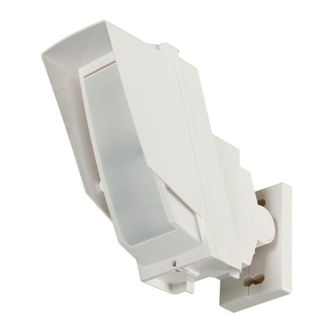
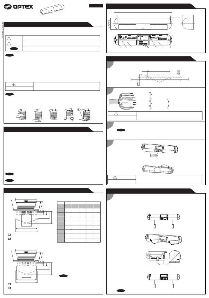
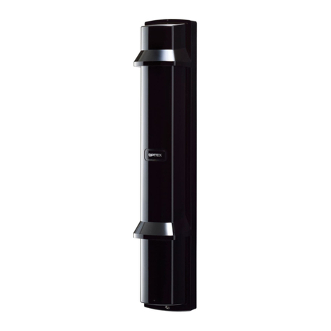
2. PARTS IDENTIFICATION
Mounting Plate
Wall Mounting Screw
Holes & Waterproof
Plug (x 4)
Vertical Alignment Dial
Terminals
See 5. “TERMINAL” on PAGE6.
Horizontal Alignment Dial
View Finder
Cover Lock Screw
Cover
Unit Base
Mounting Screw
(x 4)
Wiring Hole (x 2)
Monitor Jack
Alignment Level Indicator
Unit Base Pole Mounting
Screw Holes &
Waterproof
Plug (x 4)
Rubber
Bushing
Rubber Bush Slot
Pole Mounting
Screw Holes &
Waterproof Plug
(x 4)
Hood
Hood
Switch Section
Transmitter
Receiver
Clears the registered address (see 14. “TROUBLESHOOTING” on Page15).
Indicates the registered address by the flickering of the six indicator LEDs for about 10
seconds (see 14. “TROUBLESHOOTING” on Page15).
Switches between high and low the level of infrared beam reception output to the monitor
jack.
Use this switch for multi-level installation (see 7-2. “Master/slave selector switch setting” on
Page8).
Switches the interruption time between the four settings (see 8. “BEAM INTERRUPTION TIME
ADJUSTMENT” on Page11).
This switches the detection time for the top unit when AX-350DH TS / BT in the OR mode.
Switch to the AND mode for detection of simultaneous interruption for the top and the bottom
units and to the OR mode for detection of interruption for either unit (see 7-3. “AND/OR
selector switch setting” on Page8).
Turning the switch to ON in the OR mode fixes the interruption time for the bottom unit to one
second (see 8. “BEAM INTERRUPTION TIME ADJUSTMENT” on Page11).
ADDRESS CLEAR:
ADDRESS CHECK:
MONITOR JACK switch:
MASTER/SLAVE switch:
INTERRUPTION TIME switch:
AND/OR switch:
(AX-350DH TS / BT only)
Resets the registered address to the factory settings
(see 14. “TROUBLESHOOTING” on Page15).
Indicates the registered address by the flickering of the six indicator LEDs for about 10 seconds
(see 14. “TROUBLESHOOTING” on Page15).
Switches between high and low the level of infrared beam reception output to the monitor jack.
Use this switch for multiple beam installation (see 7-2. “Master/slave selector switch setting” on Page8).
When more than one detector with the same address is on the alarm line, switches one of them
to prevent malfunction caused by cross talk (see 14. “TROUBLESHOOTING” on Page15).
Switch to the AND mode for detection of simultaneous interruption for the top and the bottom
units and to the OR mode for detection of interruption for either unit (see 7-3. “AND/OR selector
switch setting” on Page8).
ADDRESS CLEAR:
ADDRESS CHECK:
MONITOR JACK switch:
MASTER/SLAVE switch:
FORCED ADDRESS switch:
AND/OR switch:
(AX-350DH TS / BT only)
BOTTOM UNIT INTERRUPTION TIME switch:
(AX-350DH TS / BT only)
3. NOTES ON INSTALLATION
[2] Alignment angle[1] Detection range and installation height [3] Pole mounting
·Pole size should be diameter
1.9inch(48mm).
·The length of the wiring cable out of
the pole should be within 23.5
inch(60cm).
Without AX-350DH BT
180 degrees (± 90 degrees) 40 degrees (± 20 degrees)
AX-350DH BT
120 degrees (± 60 degrees) 90 degrees (± 45 degrees)
distances between the Receiver and
the Transmitter are listed below:
Horizontally Vertically
35-350ft.(10-100m) : AX-350DH MK III, AX-350DH TS,
AX-350DH BT
65-650ft. (20-200m) : AX-650DH MK III
Normally, the installation height should
be 0.7 – 1.0m. When OR mode is used,
the installation height of lower beam
should be 15cm from the ground.
For best performance, avoid aligning
detectors at 45 degree angles except
AX-350DH BT.
Note
