manuals.online logo
Brands
  1. Home
  2. •
  3. Brands
  4. •
  5. Optex
  6. •
  7. Security Sensor
  8. •
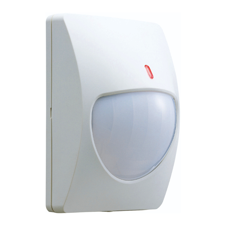
  9. Optex CX-702S User manual

Optex CX-702S User manual

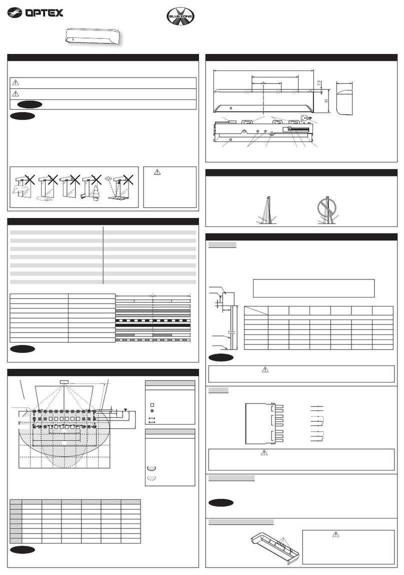
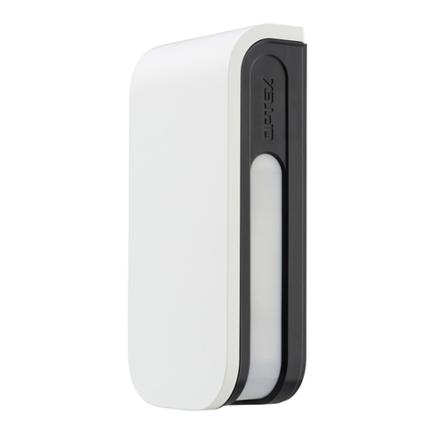
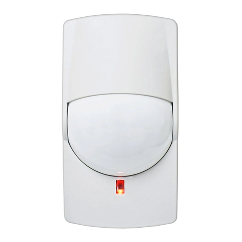
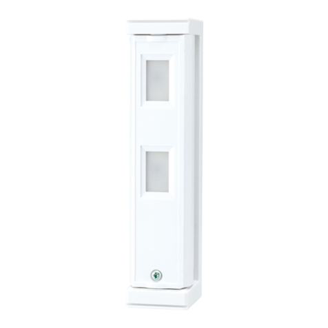
CX-702RS , CX-702S
PASSIVEINFRARED DETECTOR
INSTALLATIONINSTRUCTIONS
14
PASSIVEINFRARED DETECTOR
CX-702RS , CX-702S
INSTALLATION HINTS
1
DETECTION AREA
2
9
TROUBLE SHOOTING
8
EGNARGNOLELGNAEDIW
No.59-0974-5 2111-26
Avoid direct sunlight.
Avoid vapor or high
humidity that can
cause condensation.
Do not install outdoors.
Avoid Curtain,Screen,etc.
blocking detection area.
14
5
3
678
2
This symbol indicates prohibition.
• This unit is designed to detect movement of an intruder and activate an
alarm control panel.
• Being only a part of acomplete system, we cannot accept responsibility
for any damages or other consequences resulting from an intrusion.
Note>>
Avoid mounting detector where
movement of Fans or Air
Conditioning Fans can be
detected.
Never repair or modify
product. It may cause
accident, fire hazard or
electric shock. Mount securely.
A falling product
may cause injury.
When damage has occurred to
the product, i.e. water logged,
abnormal things inside product,
overheating or smoking, strange
smells etc., immediately stop
using product and contact your
supplier. Otherwise, continued
use in such condition may cause
electric shock or fire hazard.
WARNING
WARNING
CAUTION
Dimensions
mm (inch)
140 (5.51)
69 (2.72)
SIDE VIEW
A
0
TOP VIEW
0 5 10 15 20 21 m
30
10
5
0
5
10 m
20
10
0
10
20
10 20 30 40 50 60 70 ft.
30ft.
0 5 10 15 20 21
1.5
2.4 m
m
0 10 20 30 40 50 60 70 ft.
8
5
ft.
0 5 10 15 20 25 30 35 40 45
1.5
2.4 m
m
0 10 20 30 40 50 60 70 80 90 100 110 120 130 140 150 ft.
8
5
ft.
B
0 5 10 15 20 25 30 35 40 45
1.5
2.4
3.6 m
m
0 10 20 30 40 50 60 70 80 90 100 110 120 130 140 150 ft.
12
8
5
ft.
C
A
B
C
0 5 10 15 20 25 30 35 40 45
1.5
2.4
3.6 m
m
10 20 30 40 50 60 70 80 90 100 110 120 130 140 150 ft.
12
8
5
ft.
TOP VIEW
SIDE VIEW
0 5 10 15 20 25 30 35 40 45
m
m
0 10 20 30 40 50 60 70 80 90 100 110 120 130 140 150 ft.
5
0
52
1
0
1
2
ft.
120251010
1.5
2.4
3.6 m
m
0 10 20 30 40 50 60 70 ft.
12
8
5
ft.
0 5 10 15 20 21
1.5
2.4
3.6 m
m
0 10 20 30 40 50 60 70 ft.
12
8
5
ft.
5
00
**ATTENTION**
The specified detection area can be achieved by mounting the unit at a height of 2.4 m (8 ft.).
Mounting at a lower or higher height may reduce the area of coverage
100 (3.94)
10 SPECIFICATIONS
* Specifications and design are subject to change without prior notice.
EU & UK contact information
https://navi.optex.net/cert/contact/
OPTEX INC./AMERICAS HQ (U.S.)
www.optexamerica.com
OPTEX (EUROPE) LTD./EMEA HQ (U.K.)
www.optex-europe.com
OPTEX SECURITY B.V.
(The Netherlands)
www.optex-europe.com/nl
OPTEX SECURITY SAS (France)
www.optex-europe.com/fr
OPTEX SECURITY Sp.z o.o. (Poland)
www.optex-europe.com/pl
OPTEX PINNACLE INDIA,
PVT., LTD. (India)
www.optexpinnacle.com
OPTEX KOREA CO.,LTD. (Korea)
www.optexkorea.com
OPTEX (DONGGUAN) CO.,LTD.
SHANGHAI OFFICE (China)
www.optexchina.com
OPTEX (Thailand) CO., LTD. (Thailand)
www.optex.co.th
Copyright (C) 2016-2021 OPTEX CO.,LTD.
OPTEX CO., LTD. (JAPAN)
www.optex.net
EN
Battery operated (CE) Form C Relay
OPTIONS
- CA-1W: Wall mount bracket/ CA-2C: Ceiling mount bracket;
Adjustable ±45˚(Horizontally), 0 to 20˚(Vertically downwards)
- BA-70: Backbox for wireless transmitter
CX-702RS only
- Low current draw: 5µA (Normal in standby)
- Battery operated
- Form C alarm output and tamper switch
CX-702S only
- Form C alarm output relay
- LED ON/OFF switch
FEATURES
- Selectable “WIDE ANGLE” and “LONG RANGE” detection patterns
- Double conductive shielding of the pyroelectric element, extremely high light
- Multifocus optics design (Patent listed)
- Sealed optics
- Easy installation
PROBLEM
Alarm is not activated although
someone is walking in the
detection area.
Alarm condition when no alarm is
activated although nobody is in
the area.
LED does not light up
at the time of walk test.
PROBLEM
LED does not light.
LED lights even though no person
within area.
LED lights but
signal is not sent.
PROBLEM CAUSE
Detection area is improper.
Transmitter is not connected to PIR.
Wireless transmitter has not arrived at a receiver.
Battery is dead.
Walk test switch is OFF.
Polarity of the detector is improper.
Power supply voltage is improper. (disconnection or low voltage)
Moving object within detection area. (curtain, wall hanging, etc.)
Temperature of object within area is changing rapidly.
(heater, air conditioning, etc.)
Walk test switch is OFF.
Battery is dead.
PROBLEM CAUSE
Power supply voltage is improper. (disconnection or low voltage)
Detection area is improper.
LED switch is OFF.
Polarity of the detector is improper.
Moving object within detection area.(curtain, wall hanging, etc.)
Temperature of object within area is changing rapidly.
(heater, air conditioning, etc.)
Relay contact is stuck or damaged due to overloading.
REMEDY
Conduct a walk test. See section 2 and 7-3.
See section 5.
Check the transmitter.
Change battery.
Turn the walk test switch ON. See section 7-3.
Replace the polarity of a terminal. See section 5.
Check the wiring is correct or not. Or there is not
a battery in the detector.
Remove the object from the detection area.
Remove the heat sources from the detection area
or relocate the detector.
Turn the walk test switch ON.
Change the battery.
REMEDY
Correct supply voltage to 9.5 - 16 V DC. See section 5.
See section 5.
Turn ON the switch. See section 7-1.
Switch positive and negative at terminal. See section 5.
Remove the heat sources from the detection area.
Remove the object from the detection area.
Check load of output. The unit needs repair or
replacement.
CX-702RS
CX-702S
Model CX-702RS CX-702S
Detection method
Coverage/
Detection zones
Mounting height
Sensitivity
Detectable speed
Alarm period
Pulse count
Power input
(Operation Voltage)
Current draw
Alarm output
Tamper switch
Warm-up period
LED indicator
RF interference
Operation temperature
Environment humidity
Weight
MAINTENANCE
Passive infrared
Wide angle 85° 21 m x 21 m (70 ft. x 70 ft.)/ 68 zones
Long range 45 m x 2.4 m (150 ft. x 8 ft.)/ 22 zones
1.5 to 3.6 m (5 to 12 ft.)
1.6℃at 0.6 m/s 2.4 m mounting height
(3℉at ft./s 8 ft. mounting height)
0.3 to 1.5 m/s (1 to 5 ft./s)
Approx. 2.5 s
Approx. 20 s, 2 or 4
3 to 9 V DC
Alkaline or Lithium battery 9.5 to 16 V DC
(2.3 to 10 V DC)
5 µA
(stand-by)
15 mA
10 mA
(Walk test, LED ON) at 9 V DC
20 mA at 12 V DC
Form C-solidstate switch Form C
10 V DC, 0.01 A max. 15 V DC, 0.2 A max.
Form C -
Approx. 90 s Approx. 60 s
Disable during normal operation Alarm condition
Alarm indicator optional (walk test)
No alarm 20 V/m No alarm 30 V/m
-10℃to +50℃(+14℉to +122℉) -20℃to +50℃(-4℉to +122℉)
95% max.
200 g (7.0 oz.)
Conduct a walk test at least once a year to confirm proper operation.
When using CX-702RS and a transmitter in common, the battery life
will be shortened depending on the transmitter type (current draw).
The assumption battery life is shown bellow. The battery life will
change depending on the temperature.
Battery life
(CX-702RS only)
Approx. 3 years/ 9 V Alkaline battery (560 mAH)
Approx. 7 years/ 3.6 V Lithium battery (850 mAH)
Approx. 10 years/ 9 V Lithium battery (1,200 mAH)
Normal
Max.
3
2
DESCRIPTION AND OPERATION
3
INSTALLATION
4
WIRING
5
ADJUSTMENTS FOR REQUIRED AREA PATTERN
6
FUNCTIONS
7
Loosen fastening screw
and remove cover.
Release hook at cover.
Then remove lens
holder from cover.
12
1
3
3
The CX-702 is designed to provide ideal detection areas for different patterns ranging from 12 m (40 ft.) to 21 m (70 ft.) Wide Angle, and 24 m
(80 ft.) to 45 m (150 ft.) Long Range. The following adjustments will provide ideal detection areas for each of these requirements.
LED ON / OFF ( CX-702S Only )
2PULSE COUNT
WALK TEST SWITCH ( CX-702RS Only )
The Detection Mode can be switched to either “2” or “4” mode
depending on the environmental conditions of the installation.
2 : For normal applications.
4 : For use in hostile areas where there may be movement of small
animals or other objects such as fax machines or curtains.
When the “4” is selected, the detector’s sensitivity may seem sluggish. It is therefore
important to always conduct a walk test to ensure that the desired coverage is given.
Jumper Pin Switch
The Alarm LED indicator can be switched either “ON” or “OFF”.
WALK TEST
1) LED lights up when the unit has detected.
2) An alarm signal is outputted whenever it detects.
1
3
DETERMINE THE AREA PATTERN 2
SELECTING WIDE ANGLE OR LONG RANGE
DETECTION
VERTICAL ADJUSTMENT OF DETECTION AREA
1. Inverting the lens will select either the Wide Angle or Long Range detection patterns.
2. Please note markings “W (Wide Angle) ” and “L (Long Range) ”, on each side of lens.
3. For Wide Angle, “W” will be on top of lens.
4. For Long Range, “L” will be on top of lens.
1. Set the upper edge of the lens at either the “A”, “B” or “C” position.
2. The following chart illustrates the different position setting.
3. Confirm the detection area by conducting a walk test.
Before making adjustments, determine the pattern area,
detection range mounting height.
Adjust the vertical angle according to the desired detection
range and mounting height.
Remove lens holder carefully.
Select wide angle or long range according
to Section 6-2.
(Note:Factory default is WIDE ANGLE.)
Check to confirm that the lens is in the
desires position. Press down the lens
holder until it clicks into place along the
guide of cover.
Conduct a walk test and make
adjustments (Section 7).
Fit cover using fastening screw.
456
Guides of Cover
Guides of Lens Holder
2
ON OFF
4
Do not use pulse count 4
for Long Range detection.
Always conduct a walk test after
changing the position of this
switch to ensure the detector is
still providing optimum coverage.
CAUTION
NORMAL: Normal Operation (Battery Saving Mode)
1) LED does not lights up even though the unit detects.
2) The succeeding signals are not outputted even though it detects within 2 minutes
after the first alarm is outputted. This is in order to save the battery consumption. WALK TEST NORMAL
W : WIDE ANGLE
DISTANCE
HEIGHT
1.8 (6)
2.4 (8)
3.6 (12)
12 (40) 15 (50) 18 (60) 21 (70)
BAAA
CCCC
CCCC
L : WIDE ANGLE
DISTANCE
HEIGHT
1.8 (6)
2.4 (8)
3.6 (12)
24 (80) 30 (100) 36 (120) 45 (150)
BBAA
CCCC
CCCC
m (ft.)
CAUTION
W
W
L
A
B
C
Lens Holder
Lens
LED ON/OFF switch
Pulse count
selector (2/4)
Walk test switch
(must be OFF
for normal operation)
CX-702RS CX-702S
TAMPER
(Form C)
ALARM OUTPUT
(Form C)
POWER INPUT
(Use 3 to 9 V
Alkaline or
Lithium Battery)
ALARM OUTPUT
(Form C)
POWER INPUT
(9.5 to 16 V DC)
CX-702RS CX-702S Power wires should not exceed
the following lengths.
WIRE SIZE
AWG 22 (0.33 mm2)
AWG 20 (0.52 mm2)
AWG 18 (0.83 mm2)
12 V
300 m
(990 ft.)
470 m
(1,560 ft.)
760 m
(2,500 ft.)
14 V
650 m
(2,150 ft.)
1,030 m
(3,390 ft.)
1,650 m
(5,410 ft.)
CX-702S
When using two or more units on one wire, the
maximum length is obtained by dividing the
maximum wire length listed above by the
number of units used.
Connect tamper terminals to
a 24 hour supervisory loop.
Cover LED indicator
Lens
Cover fastening screw Base
Battery space
Terminals
Tamper switch
Sensor
Do not touch.
Terminals
Sensor
Do not touch.
Wiring knockout
Mounting knockout
Pitch 83.5 mm (3.29 inch)
Corner mount knockout
Double conductive shield
Do not touch.
Lens holder
Wiring knockout
Mounting knockout
Pitch 83.5 mm (3.29 inch)
Corner mount knockout
When you remove the PCB, push down
on the hook under PCB and remove it
from its base. Attachment of PCB is the
reverse of removal. Do not remove PCB
from base of CX-702RS.
For wiring, put the point of screw-driver in wiring
knockout of base, and hit the top of driver to crack
into knockouts.
Lead in wires through knockouts along the wiring
guide on the rear side of base.
Mount base with supplied screws.
When using a bracket, check matching knockout
position before opening mounting holes.
Wire according to Section 5.
1.
2.
3.
4.
5.

This manual suits for next models

1

Other Optex Security Sensor manuals

Optex Boundary Gard BX-80N Manual

Optex

Optex Boundary Gard BX-80N Manual

Optex RLS-50100V User manual

Optex

Optex RLS-50100V User manual

Optex REDSCAN PRO RLS-50100V User manual

Optex

Optex REDSCAN PRO RLS-50100V User manual

Optex FlipX Series User manual

Optex

Optex FlipX Series User manual

Optex OA-PRESENCE TN User manual

Optex

Optex OA-PRESENCE TN User manual

Optex CX-702 MKII User manual

Optex

Optex CX-702 MKII User manual

Optex sensor User manual

Optex

Optex sensor User manual

Optex WFX-360HW User manual

Optex

Optex WFX-360HW User manual

Optex FMX-DT-X5 User manual

Optex

Optex FMX-DT-X5 User manual

Optex OA-AXIS I User manual

Optex

Optex OA-AXIS I User manual

Optex HX-40 User manual

Optex

Optex HX-40 User manual

Optex InSight INS-QXI-ST User manual

Optex

Optex InSight INS-QXI-ST User manual

Optex OVS-6000 User manual

Optex

Optex OVS-6000 User manual

Optex AIR-SLIDE T User manual

Optex

Optex AIR-SLIDE T User manual

Optex RXC-RDT-X5 User manual

Optex

Optex RXC-RDT-X5 User manual

Optex BX SHIELD User manual

Optex

Optex BX SHIELD User manual

Optex BX SHIELD Series User manual

Optex

Optex BX SHIELD Series User manual

Optex HX-40 User manual

Optex

Optex HX-40 User manual

Optex HX-80NRAM User manual

Optex

Optex HX-80NRAM User manual

Optex ELITE T User manual

Optex

Optex ELITE T User manual

Optex REDSCAN Series User manual

Optex

Optex REDSCAN Series User manual

Optex fit Series User manual

Optex

Optex fit Series User manual

Optex WX Infinity Series User manual

Optex

Optex WX Infinity Series User manual

Optex VX Shield Series User manual

Optex

Optex VX Shield Series User manual

Popular Security Sensor manuals by other brands

schmersal RSS 36-I2-SD-ST-DU manual

schmersal

schmersal RSS 36-I2-SD-ST-DU manual

IDEM SAFETY SWITCHES KL1-P operating instructions

IDEM SAFETY SWITCHES

IDEM SAFETY SWITCHES KL1-P operating instructions

Wiseup WBD100 user guide

Wiseup

Wiseup WBD100 user guide

Leviton decora ODS10-TD Series installation instructions

Leviton

Leviton decora ODS10-TD Series installation instructions

RESKAL LD25 user guide

RESKAL

RESKAL LD25 user guide

AdirPro MC-10 quick start guide

AdirPro

AdirPro MC-10 quick start guide

DMP Electronics 1183 Series installation guide

DMP Electronics

DMP Electronics 1183 Series installation guide

Ecolink TX-E611 Installation sheet

Ecolink

Ecolink TX-E611 Installation sheet

Pfeiffer Vacuum ASI 35 Maintenance instructions

Pfeiffer Vacuum

Pfeiffer Vacuum ASI 35 Maintenance instructions

B.E.G. LUXOMAT PD4-M-DIM-HVAC 16A Installation and operating instruction

B.E.G. LUXOMAT

B.E.G. LUXOMAT PD4-M-DIM-HVAC 16A Installation and operating instruction

Robertshaw VIBRASWITCH EURO366G instruction manual

Robertshaw

Robertshaw VIBRASWITCH EURO366G instruction manual

Scott Alpride Series quick start guide

Scott

Scott Alpride Series quick start guide

jablotron JA-150P Installation

jablotron

jablotron JA-150P Installation

Locatechs LocaSafe VA10 Base Station Installation and operating manual

Locatechs

Locatechs LocaSafe VA10 Base Station Installation and operating manual

American Dynamics DuoTect-C AD1562 Installation and operating instructions

American Dynamics

American Dynamics DuoTect-C AD1562 Installation and operating instructions

Philips 17266xx16 Series user manual

Philips

Philips 17266xx16 Series user manual

ion science PhoCheck+ Series user manual

ion science

ion science PhoCheck+ Series user manual

Renkforce 1362922 operating instructions

Renkforce

Renkforce 1362922 operating instructions

manuals.online logo
manuals.online logoBrands
  • About & Mission
  • Contact us
  • Privacy Policy
  • Terms and Conditions

Copyright 2025 Manuals.Online. All Rights Reserved.