manuals.online logo
Brands
  1. Home
  2. •
  3. Brands
  4. •
  5. Optex
  6. •
  7. Security Sensor
  8. •
  9. Optex CX-702RS User manual

Optex CX-702RS User manual

PASSIVE INFRARED DETECTOR
CX-702RS , CX-702S
No.59-0974-3 0708-30
BATTERY OPERATED (CE) Form C Relay (CX-702RS Only)
FEATURES
Selectable ”WIDE ANGLE” and “LONG RANGE”
detection patterns.
Double Conductive Shielding of the pyroelectric
element - Extremely High Light.
Multifocus Optics Design (Patent listed)
Sealed Optics
Easy Installation
CX-702RS Only
Low Current Draw : 5µA (Normal. In Standby)
Battery Oparated
Form C Alarm Output and Tamper Switch
OPTION
CA-1W : Wall Mount Bracket ; Adjustable ±45°(Horizontally), 0-20°(Vertically downwards)
CA-2C : Ceiling Bracket ; Adjustable ±45°(Horizontally), 0-20°(Vertically downwards)
BA-70 : Backbox for wireless transmitter
CX-702S Only
Form C Alarm Output Relay
LED On/Off Switch
1.INSTALLATION HINTS
1
Avoid direct sunlight.
2
Avoid mounting detector where
movement of Fans or Air
Conditioning Fans can be detected.
3
Avoid vapor or high humidity
that can cause condensation.
4
Avoid blocking detection area
with curtain, screen, etc.
5
Do not install in the outdoors.
6
WARNING
Never repair or modify
product. It may cause
accident, fire hazard or
electric shock.
7
WARNING
When damage has occured to the
product, i.e. water logged, abnormal
things inside product, overheating or
smoking, strange smells etc.,
immediately stop using product and contact your supplier.
Otherwise, continued use in such condition may cause
electric shock or fire hazard.
8
CAUTION
Mount securely.
Fall of A product
may cause injury.
2.DETECTION AREA
●
●
●
●
●
●
●
●
●
**ATTENTION**
The specified detection area can be achieved by mounting the unit at a height of 2.4m. Mounting at a lower or higher height may reduce the area of coverage.
●
12 3
456
3.DESCRIPTION AND OPERATION
4.INSTALLATION
Loosen fastening screw
and remove cover.
For wiring, put the point of screw-
driver in wiring knockouts of base,
and hit the top of dirver to crack into
knockouts. Lead in wires through
knockouts along the wiring guide on
the rear side of base. Mount base
with supplied screws. When using a
bracket, check matching knockout
position before opening mounting
holes.Wire according to Section 5.
When you remove the PCB, push down
on the hook under PCB and remove it from
its base. Attachment of PCB is the reverse
of removal. Do not remove PCB from base
of CX-702RS.
Release hook at cover.
Then remove lens holder
from cover.
Remove lens holder carefully.
Select wide angle or long range
according to Section 6-2. (Note:
Factory default is wide area)
Check to confirm that the lens is in
the desires position.Press down the
lens holder until it clicks into place
along the guide of cover.
Conduct a walktest and
make adjustments
(Section 7). Fit cover
using fastening screw.
Guides of Cover
Guides of Lens Holder
TAMPER
(Form C)
ALARM OUTPUT
(Form C)
POWER INPUT
(Use 3 - 9V
Alkaline or
Lithium Battery)
ALARM OUTPUT
  (Form C)
POWER INPUT
(9.5 - 16 VDC)
Power wires should not exceed
  the following lengths.
When using two or more units on one wire, the
maximum length is obtained by dividing the
maximum wire length listed above by the
number of units used.
WIRESIZE 12V 14V
990ft 2150ft
(300m ) (650m )
1560ft 3390ft
(470m ) (1030m )
2500ft 5410ft
(760m ) (1650m )
CX‑702S
AW G22(0.33m m 2)
AWG20(0.52m m 2)
AWG18(0.83m m 2)
Cover LED Indicator
Lens
Cover Fastening Screw
Base
CX-702RS
CX-702S
Battery Space
Terminals
Tamper switch
 Sensor
Do not touch.
Terminals
Sensor
Do not touch.
Wiring Knockout
Mounting Knockout
Pitch 3.29 inch (83.5mm)
Corner mount Knockout
Wiring Knockout
Mounting Knockout
Pitch 3.29 inch (83.5mm)
Corner mount Knockout
Double Conductive Shield
Do not touch.
Lens Holder
Connect tamper terminals to
a 24 hour supervisory loop.
[]
CX-702RS CX-702S
− + − +
5.WIRING
6.ADJUSTMENTS FOR REQUIRED AREA PATTERN
The CX-702 is designed to provide ideal detection areas for different patterns ranging from 40ft.(12m) to 70ft.(21m) Wide Angle,
and 80ft.(24m) to 150ft.(45m) Long Range.
The following adjustments will provide ideal detection areas for each of these requirements.
1. DETERMINE THE AREA PATTERN
Before making adjustments, determine the area pattern - detection range mounting height.
2.SELECTING WIDE ANGLE OR LONG RANGE DETECTION
1. Inverting the lens will select either the Wide Angle or Long Range detection patterns.
2. Please note markings “W(Wide Angle)” and
“L(Long Range)”, on each side of lens.
3. For Wide Angle, “W” will be on top of lens.
4. For Long Range, “L” will be on top of lens.
3.VERTICAL ADJUSTMENT OF DETECTION AREA
Adjust the vertical angle according to the desired detection range and mounting height.
1. Set the upper edge of the lens at
either the “A”, “B” or “C” position.
2. The following chart illustrates the
different position setting.
3. Confirm the detection area by
conducting a walktest.
7.FUNCTIONS
40 (12) 50 (15) 60 (18) 70 (21) 80 (24) 100 (30) 120(36) 150(45)
6 (1.8)
BAAA
6 (1.8)
BBAA
8 (2.4)
CCCC
8 (2.4)
CCCC
12 (3.6)
CCCC
12 (3.6)
CCCC
DISTANCE
HEIGH
T
W : WIDE ANGLE L : LONG RANGE
HEIGHT
DISTANCE
ft.(m)
Always conduct a walktest after
changing the position of this
switch to ensure the detector is
still providing optimum coverage.
CX-702RS CX-702S
LED ON / OFF Switch
Pulse Count
Selector (2 / 4)
Walk Test Switch
(Must be OFF for normal operation)
CAUTION!
1. LED ON / OFF (CX-702S Only)
The Alarm LED indicator can be switched either “ON” or “OFF”
ON OFF
2. PULSE COUNT
The Detection Mode can be switched to either “2” or “4” mode
depending on the environmental conditions of the installation.
2 : For normal applications.
4 : For use in hostile areas where there may be movement of small animals or
other objects such as fax machines or curtains.
When the “4” is selected, the detector’s sensitivity may seem sluggish. It is therefore important to always
conduct a walktest to ensure that the desired coverage is given.
3. WALK TEST SWITCH (CX-702RS Only)
WALK TEST
1) LED lights up when the unit has detected.
2) An alarm signal is outputted whenever it detects.
NORMAL : Normal Operation (Battery Saving Mode)
1) LED does not light up even though the unit detects.
2) The succeeding signals are not outputted even though it detects within 2 minutes
after the first alarm is outputted. This is in order to save the battery consumption.
24
WALK TES NORMAL
CAUTION!
Do not use pulse
count 4 for Long
Range detection.
8.TROUBLE SHOOTING
9.MAINTENANCES
10.SPECIFICATIONS
CX-702RS
CX-702S
Conduct a walktest at least once a year to confirm proper operation.
When using CX-702RS and a transmitter in common, the battery life
will be shortened depending on the transmitter type (Current Draw).
The assumption battery life is shown in the right table. The battery life
will change depending on the temperature.
PROBLEM
Alarm is not activated
although someone is
walking in detection area.
Alarm condition when no
Alarm is activated although
nobody is in the area.
LED does not light up at
the time of walktest.
PROBABLE CAUSE
Detection area is improper.
Transmitter is not connected to PIR.
Wireless transmission has not arrived at a receiver.
Battery is dead.
Walk Test switch is OFF.
Polarity of the detector is Improper.
Power supply voltage is Improper.(Disconnection
or low voltage)
Moving object within detection area.
(curtain, wall hanging, etc.)
Temperature of object within area is changing
rapidly (heater, air conditioning, etc.)
Walk Test switch is OFF.
Battery is dead.
REMEDY
Conduct a walktest. See Section 2 and 7-3.
See Section 5.
Check the transmitter.
Change battery.
Turn the walktest switch on. See Section 7-3.
Replace the polarity of a terminal. See Section 5.
Check the wiring is correct or not. Or there is not
a battery in the detector.
Remove the object from the detection area.
Remove the heat sources from the detection area
or relocate the detector.
Turn the walktest switch on.
Change battery.
PROBLEM
LED does not light.
LED lights even
though no person
within area.
LED lights but
signal is not sent.
PROBABLE CAUSE
Improper power supply voltage.
(disconnection,low voltage)
Improper detection area.
LED switch is OFF.
Improper polarity to detector.
Moving object within area. (curtain, wall hanging, etc.)
Temperature of object within area changing rapidly
(heater, air conditioning, etc.)
Relay contact is stuck or damaged due to overloading.
REMEDY
Correct supply voltage to 9.5 - 16V DC. See Section 5.
See Section 2.
Turn on the switch. See Section 7-1.
Switch positive and negative at terminal.See Section 5.
Remove the souces from the detection area.
Remove object from the detection area.
Check load of output.
The unit needs repair or replacement.
Battery Life
(CX-702RS Only)
Approx. 3 years / 9V Alkaline Battery (560mAH)
Approx. 7 years / 3.6V Lithium Battery (850mAH)
Approx. 10 years / 9V Lithium Battery (1200mAH)
Model
Detection method
Coverage
Detection zones
Mounting height
Sensitivity
Detectable speed
Alarm period
Pulse count
Environment humidity
Weight
CX-702RS / CX-702S
Passive infrared
Wide Angle 85°wide Long Range
70ft. × 70ft. 150ft. × 8ft.
(21m × 21m) (45m × 2.4m)
68 zones 22 zones
5 - 12ft.(1.5 - 3.6m)
3°F at 2ft./sec., 8ft. mounting height
(1.6°C at 0.6m/sec., 2.4m mounting height)
1- 5ft. / sec. (0.3 - 1.5m/sec.)
Approx. 2.5 sec.
Approx. 20 sec. 2 or 4
95% max.
7.0oz (200g)
Model
Power input
Operating Voltage
Current draw
Alarm output
Tamper switch
Warm-up period
LED indicator
RF interference
Operating temperature
CX-702RS
3 - 9VDC Alkaline Battery or Lithium Battery
2.3 - 10VDC
5µA (normal : In Standby) at 9VDC
10mA (max. : In Walktest, LED on) at 9VDC
Form C-Solid State Switch 10VDC 0.01A max.
Form C.
Approx. 90 sec.
Disabled during normal operation
Alarm indicator optional (Walktest)
No alarm 20V/m
+14°F - +122°F(-10°C - +50°C)
Model
Power input
Current draw
Alarm output
Warm-up period
LED indicator
RF interference
Operating temperature
CX-702S
9.5 - 16VDC
15mA(normal) / 20mA(max.) at 12VDC
Form C. 15VDC 0.2A max.
Approx. 60 sec.
Alarm condition
No alarm 30V/m
-4°F - +122°F(-20°C - +50°C)
Dimensions : inches (mm)
*Specifications and design are subject to change without prior notice.
This unit is designed to detect movement of an intruder and activate an alarm control panel. Being only a part of a complete system, we cannot accept
responsibility for any damages or other consequences resulting from an intrusion. This product confirms to the EMC Directive 89/336 EEC.
OPTEX CO., LTD.
(JAPAN)
(ISO9001 Certified by LRQA)
(ISO14001 Certified by JET)
5-8-12 Ogoto
Otsu, Shiga 520-0101
Japan
Tel:+81-77-579-8670
Fax:+81-77-579-8190
URL:http://www.optex.co.jp/e
OPTEX INCORPORATED(USA)
URL:http://www.optexamerica.com
Tel:+1-909-993-5770
Tech:(800)566-7839
OPTEX (EUROPE) LTD.(UK)
URL:http://www.optexeurope.com
Tel:+44-1628-631000
OPTEX SECURITY SAS (FRANCE)
URL:http://www.optex-security.com
Tel:+33-437-55-50-50
OPTEX KOREA CO., LTD.(KOREA)
URL:http://www.optexkorea.com
Tel:+82-2-719-5971
OPTEX SECURITY Sp.z o.o.(POLAND)
Tel:+48-22-598-06-55
5909743 07.08.30
5.51(140)
3.94(100)
2.72(69)
OPTEX(DONGGUAN) CO., LTD.
SHENZHEN OFFICE(CHINA)
URL:http://www.optexchina.com
Tel:+86-755-33302950
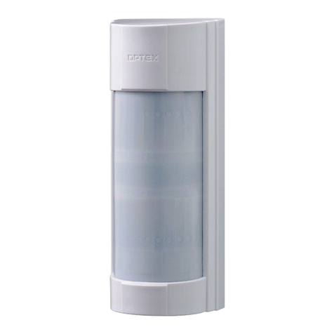
This manual suits for next models

1

Other Optex Security Sensor manuals

Optex PRO SWING OA-EDGE1 T User manual

Optex

Optex PRO SWING OA-EDGE1 T User manual

Optex VX Shield Series User manual

Optex

Optex VX Shield Series User manual

Optex X-ZONE User manual

Optex

Optex X-ZONE User manual

Optex Fit Series User manual

Optex

Optex Fit Series User manual

Optex FX-50QZ User manual

Optex

Optex FX-50QZ User manual

Optex FMX-DT-X5 User manual

Optex

Optex FMX-DT-X5 User manual

Optex VX-402R User manual

Optex

Optex VX-402R User manual

Optex OA-AXIS I User manual

Optex

Optex OA-AXIS I User manual

Optex InSight INS-QXI-ST User manual

Optex

Optex InSight INS-QXI-ST User manual

Optex Smart Line Series User manual

Optex

Optex Smart Line Series User manual

Optex fit Series User manual

Optex

Optex fit Series User manual

Optex OVS-50TNR User manual

Optex

Optex OVS-50TNR User manual

Optex HX-80NRAM User manual

Optex

Optex HX-80NRAM User manual

Optex AX-70TN User manual

Optex

Optex AX-70TN User manual

Optex OA-PRESENCE TN User manual

Optex

Optex OA-PRESENCE TN User manual

Optex OML-ST User manual

Optex

Optex OML-ST User manual

Optex OVS-01GT User manual

Optex

Optex OVS-01GT User manual

Optex AX-70TN User manual

Optex

Optex AX-70TN User manual

Optex OA-4500S User manual

Optex

Optex OA-4500S User manual

Optex SL-100 TNR User manual

Optex

Optex SL-100 TNR User manual

Optex HX-40 User manual

Optex

Optex HX-40 User manual

Optex FLX-S-ST User manual

Optex

Optex FLX-S-ST User manual

Optex VX-402R User manual

Optex

Optex VX-402R User manual

Optex HX-40 User manual

Optex

Optex HX-40 User manual

Popular Security Sensor manuals by other brands

Siemens FDB22 Series Assembly

Siemens

Siemens FDB22 Series Assembly

Raypak Latching Lockout Module C-5 product manual

Raypak

Raypak Latching Lockout Module C-5 product manual

Rigaku Smartlab SE + HyPix-400 instruction manual

Rigaku

Rigaku Smartlab SE + HyPix-400 instruction manual

METREL 20992336 operating instructions

METREL

METREL 20992336 operating instructions

STEINEL HF 360-2 COM1 manual

STEINEL

STEINEL HF 360-2 COM1 manual

FT Technologies Acu-Res Acu-Vis 2.0 user manual

FT Technologies

FT Technologies Acu-Res Acu-Vis 2.0 user manual

C-LOGIC 630-MD instruction manual

C-LOGIC

C-LOGIC 630-MD instruction manual

Niko 351-25456 user manual

Niko

Niko 351-25456 user manual

THORLABS PDAPC1 user guide

THORLABS

THORLABS PDAPC1 user guide

Bosch ZX835 installation instructions

Bosch

Bosch ZX835 installation instructions

aguilera AE/SA-OPT manual

aguilera

aguilera AE/SA-OPT manual

Trotec BE15 operating manual

Trotec

Trotec BE15 operating manual

CS Instruments LD 500 instruction manual

CS Instruments

CS Instruments LD 500 instruction manual

SEW LVD-20 instruction manual

SEW

SEW LVD-20 instruction manual

Bolid Security Systems S2000-PIK instruction manual

Bolid Security Systems

Bolid Security Systems S2000-PIK instruction manual

UTC Fire and Security Det-Tronics X2200 instructions

UTC Fire and Security

UTC Fire and Security Det-Tronics X2200 instructions

GEV NATALIA 10888 manual

GEV

GEV NATALIA 10888 manual

Latchways ManSafe SRL User instructions

Latchways

Latchways ManSafe SRL User instructions

manuals.online logo
manuals.online logoBrands
  • About & Mission
  • Contact us
  • Privacy Policy
  • Terms and Conditions

Copyright 2025 Manuals.Online. All Rights Reserved.