Q I G Quick Installation Guide
PRINTED ON RECYCLED PAPER
Version 1.0
Quick Installation Guide
Po w e r
Redund a nt Inpu t p ower
Power co n sumpt i on(Typ.) 13 . 2 Wa tts
Ov erloa d c urren t p rotec t ion Pr e sent
Ph y s ical Characte r i stic
En c losur e I P-30
Di m ensio n ( W x D x H) 54 . 3 (W) x 10 8 .3 (D) x 14 5 .1 (H) mm ( 2 .13 x 4.2 6 x 5.71 in c hes)
RS - 232 Ser i al Con s ole Po rt
Sw itch Pr o perti e s
Sw itchi n g laten c y: 7 us
Sw itchi n g bandw i dth: 24 G bps
Th r oughp u t (pac k et per se c ond) : 1 7 .856M p ps@64 B ytes pa c ket
Ma x . Numbe r o f Availab l e VLANs : 4 096
VL A N ID Ra n ge : VID 0 to 4 0 95
IG M P multi c ast gr o ups: 25 6 f or each V L AN
Port ra t e limi t ing: Us e r Defin e
Se c urity Feat u res
De v ice Bi n d ing se c urity f e atur e
En a ble/d i sabl e p orts, M A C based p o rt secu r ity
Port bas e d netwo r k acces s c ontr o l (802. 1 x)
VL A N (802. 1 Q ) to seg r egate a n d secur e n etwor k t raf f ic
Radius c e ntra l ized p a sswor d m anage m ent
SN M Pv3 enc r ypte d a uthen t icati o n and acc e ss secu r ity
Ht t ps / SSH e n hance n e twor k s ecuri t y
So f twar e Feat u res
ST P /RSTP / MSTP (I E EE 802 . 1D/w/ s )
Redund a nt Ring ( O -Ring ) w ith re c over y t ime les s t han 20m s over 2 5 0 units
TOS/Di f fserv s u pport e d
Qu a lity o f S ervic e ( 802.1 p ) for re a l-tim e t raff i c
VL A N (802. 1 Q) wit h V LAN tag g ing
IG M P Snoop i ng
IP - based b a ndwi d t h mana g ement
Ap p licat i on-b a sed QoS m a nagem e nt
DO S /DDOS a u to pre v entio n
Port con f igura tion , s tatus , s tatis t ics, mo n itori n g, sec u rity
DH C P Serve r/Cli e nt/Relay
SM T P Clien t
Mo d bus TC P
Et h erNet / IPTM
NT P s erve r
Ne t work Redund a ncy O- R ing, Op e n-Rin g , O-Ch a in, MRP , MS T P (RSTP / STP co m p atib l e)*N ote
RS - 232 in RJ 4 5 conn e ctor wi t h conso l e cable . B aud ra t e setti n g: 115 2 00bps , 8 , N, 1
Weig h t (g)
Ju m bo fra me Up t o 9 .6K By t es
Weig h t (g) 71 0 g 74 0 g72 2 g 73 5 g 73 5 g 74 0 g
En v i ronmental
-4 0 t o 85 C (-40 t o 1 85 F)
o o
St o rag e Tempe ratu r e
-4 0 t o 75 C (-40 t o 1 67 F)
o o
Op e rat i ng Tem p era t ure
5% t o 9 5% Non- c onde n singOp e rat i ng Humi d ity
Re g u latory Approv a l s
EN 5 5 032, CI S PR32 , E N 61000 - 3-2, EN 6 1 000-3 - 3, FCC Part 15 B cl ass AEM I
EN 5 5 024 (IE C /EN 61 0 00-4- 2 ( ESD: Co n tact 8K V, Ai r 10KV ) , IEC/E N 6 1000- 4 -3 (RS) , IEC/E N 6 1000- 4 -4 (EFT Power 4K V, Si ngle 4 K V),
IE C /EN 610 0 0-4- 5 ( S urge : Power 4 KV, RJ45 4K V ), IEC/ E N 61000 - 4-6 (CS ) , IEC/ E N 6 1000 - 4-8(P F MF), IE C /EN 610 0 0-4-1 1 ( DIP))
EM S
IE C 60068 - 2-27Sh o ck
IE C 60068 - 2-31
IE C 60068 - 2-6Vi b rat i on
EN60950-1
Sa f ety
Fr e e Fa ll
Wa r r anty
5 ye ars
Fa u l t Contact
Relay R elay o u tput to c a rry cap a city o f 1 A at 24VD C
Rever s e Pol a rity Pr o tecti o n
Pr e sent
Q I G
G I G A B I T
I N D U S T R I A L
S W I T C H
P o E
To connect the console port to an external management device, you need an RJ-45 to DB-
9 cable, which is also supplied in the package. Below is the console port pin assignment
information.
Console Port Pin Definition
PC (male) pin assignment RS-232 with DB9 (female) pin
assignment (RJ45-DB9 cable) RJ45 pin assignment
PIN#2 RxD PIN#2 RxD PIN#2 RxD
PIN#3 TxD PIN#3 TxD PIN#3 TxD
PIN#5 GND PIN#5 GND PIN#5 GND
Wiring
The switch supports dual redundant power supplies, Power Supply1
(PWR1) and Power Supply 2 (PWR2). The connections for PWR1,
PWR2 and the RELAY are located on the terminal block.
STEP 1: Insert the negative/positive wires into the V-/V+ terminals,
respectively.
STEP 2: To keep the DC wires from pulling loose, use a small flat-
blade screwdriver to tighten the wire-clamp screws on the front of the
terminal block connector.
PWR-1PWR-2
1A@24V
V2- V2+ V1- V1+
Fault
Power inputs
The two sets of relay contacts of the 6-pin terminal block connector are used to detect user-
configured events. The two wires attached to the fault contacts form an close circuit when a
user-configured event is triggered. If a user-configured event does not occur, the fault circuit
remains opened.
Relay contact
Resetting
To reboot the switch, press the button for 2-3 seconds.Reset
To restore the switch configurations back to the factory defaults, press the button for 5 seconds.Reset
Grounding and wire routing help limit the effects of noise due to electromagnetic interference
(EMI). Run the ground connection from the ground screws to the grounding surface prior to
connecting devices.
Grounding
Configurations
After installing the switch, the green power LED should turn on. Please refer to the
following tablet for LED indication.
1. Launch the Internet Explorer and type in IP address of the switch. The default static IP address is
192.168.10.1
2. Log in with default user name and password
(both are ). After logging in, you shouldadmin
see the following screen. For more information
on configurations, please refer to the user
manual. For information on operating the switch
using ORing’s Open-Vision management utility,
please go to ORing website.
Follow the steps to set up the switch:
Specifications
OR i n g Switch Model
Ph y s ical Ports
Te c h nology
Et h ernet S t anda r ds
IE E E 802.3 f o r 10Ba s e-T
IE E E 802.3 u f or 100 B ase-TX a n d 100Ba s e-FX
IE E E 802.3 a b for 10 0 0Base -T
IE E E 802.3 z f or 100 0 Base-X
IE E E 802.3 x f or Flo w c ontro l
IE E E 802.3 a d for LA C P (Link A g grega t ion Con t rol Pro t ocol )
IE E E 802.1 p f or COS ( C lass of S e rvice )
IE E E 802.1 Q f or VLA N Tagg i ng
IE E E 802.1 D f or STP ( S panni n g Tree P r otoco l )
IE E E 802.1 w f or RST P ( Rapi d S panni n g Tree P r otoc o l)
IE E E 802.1 s f or MST P ( Multi p le Span n ing Tre e Proto c ol)
IE E E 802.1 x f or Aut h entic a tion
IE E E 802.1 A B for LL D P (Link L a yer Di s cove ry Prot o col)
IE E E 802.3 a t PoE s p ecifi c atio n ( up to 30 Watts p e r port f o r P.S.E. )
10 / 100/1 0 00Ba s e-T(X) w i th
P.S. E. Po r ts in RJ4 5 Auto
MD I /MDIX
MA C Tab l e 8K
Pr i ority Q ueues 8
Pr o cessi n g Stor e -and- Forw ard
8
IG P S -9084GP-LA
PoE Outp u t Wa tts Per port 5 6 V DC, 350 m A. Max . 1 5.4 wa t ts (IEE E 8 02.3a f ),
Per Po r t 56V DC, 5 9 0mA. Ma x . 30 wat t s (IEEE 8 0 2.3a t )
50 / 57/-5 0 VDC on 6 - pin ter m inal bl o ck
10 0 /1000 B ase-X wit h S FP port 4
PWR Green On DC power on
PWR1 Green On DC power module 1 activated
PWR2 Green On DC power module 2 activated
R.M Green On Ring Master
Ring Green
On Ring enabled
Blinking
Ring structure is broken (i.e. part of the ring is
disconnected)
Fault Amber On Faulty relay (power failure or port disconnected)
PoE Green On Power supplied over Ethernet
10/100/1000Base-T(X) Gigabit PoE Ethernet ports
LNK/ACT Green
On Port link up
Blinking Data transmitted
Speed
Green On Port link at 1000Mbps
Amber On Port link at 100Mbps
Green/Amber Off Port link at 10Mbps
SFP ports
LNK/ACT Green
On Port link up
Blinking Data transmitted
*Note : This function is availa ble by request only
MT B F ( hrs)
516416hrs
10/100Base-T(X) P.S.E. RJ-45 port
TD+ with PoE Power Input +
TD- with PoE Power Input +
RD+ with PoE Power Input -
RD- with PoE Power Input -
For pin assignments for different types of cables, please refer to the following
tables.
10/100 Base-T(X) MDI/MDI-X
Pin Number MDI port MDI-X port
1 TD+(transmit) RD+(receive)
2 TD-(transmit) RD-(receive)
3 RD+(receive) TD+(transmit)
4 Not used Not used
5 Not used Not used
6 RD-(receive) TD-(transmit)
7 Not used Not used
8 Not used Not used
Note: “+” and “-” signs represent the polarity of the wires that make up each wire pair.
1000Base-T MDI/MDI-X
Pin Number MDI port MDI-X port
1 BI_DA+ BI_DB+
2 BI_DA- BI_DB-
3 BI_DB+ BI_DA+
4 BI_DC+ BI_DD+
5 BI_DC- BI_DD-
6 BI_DB- BI_DA-
7 BI_DD+ BI_DC+
8 BI_DD- BI_DC-
1000Base-T RJ-45 Port
Pin Number Assignment
1 BI_DA+
2 BI_DA-
3 BI_DB+
4 BI_DC+
5 BI_DC-
6 BI_DB-
7 BI_DD+
8 BI_DD-
10/100 Base-T(X) RJ-45 Port
Pin Number Assignments
1 TD+
2 TD-
3 RD+
4 Not used
5 Not used
6 RD-
7 Not used
8 Not used
1000Base-T P.S.E. RJ-45 port
BI_DA+ with PoE Power Input +
BI_DA- with PoE Power Input +
BI_DB+ with PoE Power Input -
BI_DB- with PoE Power Input -
ORing Industrial Networking Corp.
Copyright© 2018 ORing
All rights reserved.
TEL: +886-2-2218-1066
FAX: +886-2-2218-1014
Website: www.oringnet.com
E-mail: support@oringnet.com
PoE Po w er Supp l y Type End s pan mod e
Sh a re Dat a B uffer 4Mb i t
Re s e t Function
Reset Fu n ction < 5 sec: Sy stem r e boot, > 5 se c: Factor y d efaul t
PoE Po w er Budg e t 240 W max, 30 W /per po r t
Hi - POT 1 . 5KV AC
CE E M C (EN 550 2 4, EN 55 0 32), FC C Part 1 5 B
EM C
TB D
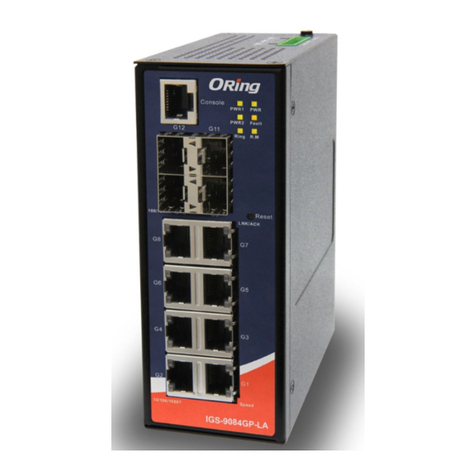
TB D
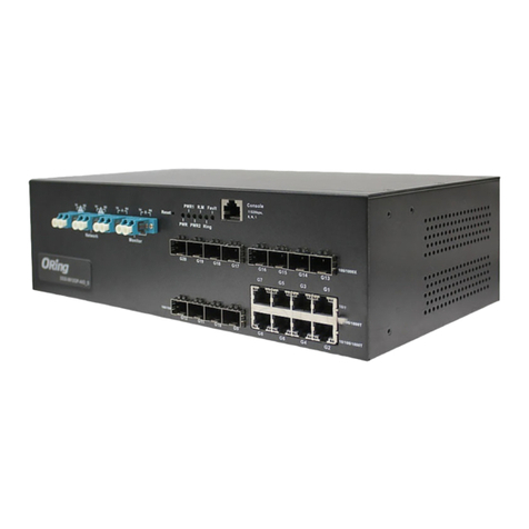
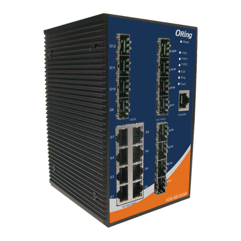
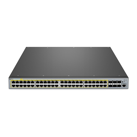
Industrial Managed PoE Gigabit Switch
IGPS-9084GP-LA
IGPS-9084GP-LA


