manuals.online logo
Brands
  1. Home
  2. •
  3. Brands
  4. •
  5. ORiNG
  6. •
  7. Switch
  8. •
  9. ORiNG TES-W9124GT-M12X-BP2-24V-IP54 User manual

ORiNG TES-W9124GT-M12X-BP2-24V-IP54 User manual

Quick Installation Guide
Version 1.0
Quick Installation Guide
Introduction
PRINTED ON RECYCLED PAPER
ORing's Transporter series managed Ethernet switches are designed for
TM
industrial waterproof applications, such as rolling stock, vehicle, and railway
applications. is managed RedundantTES-W9124GT-M12X-BP2-24V-IP54
Ring Ethernet switch with 12x10/100Base-T(X) and 4x10/100/1000Base-
T(X) ports which is specifically designed for the toughest and fully compliant
with EN50155 requirement. The switch support Ethernet Redundancy
protocol, O-Ring (recovery time < 10/30ms over 250 units of connection), O-
Chain, MRP and MSTP/RSTP/STP (IEEE 802.1s/w/D) can protect*NOTE
your mission-critical applications from network interruptions or temporary
malfunctions with its fast recovery technology. TES-W9124GT-M12X-BP2-
24V-IP54 includes 2 sets of bypass ports that protect the network from
failures and Network maintenance by ensuring network integrity during
power loss. And support wide operating temperature from -40 C to 75 C.
o o
TES-W9124GT-M12X-BP2-24V-IP54 can also be managed centralized and
convenient by Open-Vision, Except the Web-based interface, Telnet and
console (CLI) configuration. Therefore, the switch is one of the most reliable
choices for EN50155 waterproof highly-managed Ethernet application.
Package Contents
Wall-mount
Contents
CD
TES-W9124GT-M12X-BP2
-24V-IP54
Pictures Number
1
1
1
Wall-mount Kit 4
Dimension
Q I G 1907-200-SW9124X541-FX010
TES-W9124GT-M12X-BP2-24V-IP54
Preparation
Before you begin installing the device, make sure you have all of the package
contents available and a PC with Microsoft Internet Explorer 6.0 or later, for
using web-based system management tools.
Panel Layouts
Top View
Installation
QIG
1. Wall-mount screw holes
TES-W9124GT-M12X-BP2
-24V-IP54
The device is shipped with the following items. If any of these items is missing
or damaged, please contact your customer service representative for
assistance.
1
EN50155 Industrial IP-54 managed
Ethernet switch
*NOTE: This function is available by request only
Unit =mm (Tolerance ±0.5mm)
Follow the steps below to install the device to the wall.
Step 1: Screw the Four pieces of wall-mount kits onto bottom side of the switch. A total of four
screws are required.
Step 2: Hold the device upright against the wall.
Step 3: Insert four screws through the holes at the top of the plate and fasten the screws to
the wall.
1
Instead of screwing the screws in all the
way, it is advised to leave a space of about
2mm to allow room for sliding the switch
between the wall and the screws.
For pin assignments of power and console port, please refer to the following tables.
Wiring
Grounding
Grounding and wire routing help limit the effects of noise due to electromagnetic interference
(EMI). Run the ground connection from the grounding pin on the power connector to the grounding
surface prior to connecting devices.
Power port pinouts
The device supports two sets of power supply and uses the M12 S-coded
4-pin male connector on the front panel for power inputs.
Step 1: Insert a power cable to the power connector on the device.
Step 2: Rotate the outer ring of the cable connector until a snug fit is
achieved. Make sure the connection is tight.
Network Connection
When installed outdoors, make sure the connectors on the panel are facing down
to prevent water intrusion.
Do not remove the water-proof casing, and do not touch or move the device
when the antennas are transmitting or receiving signals.
When installing the device, make sure to keep the radiating at a minimum distance
of 20 cm (7.9 inches) from all persons to minimize the potential for human contact
during normal operation.
Do not operate the device near unshielded blasting caps or in an otherwise
explosive environment unless the device has been modified for such use by
qualified personnel.
Safety & Warnings
Faul tRingR.M.
Con sole
Pow er 1
G1~ G4
1 BI_D A+
2 BI_D A-
3 BI_D B+
4 BI_D B-
6
5
7
3
2
18
4
5 BI_D D+
6 BI_D D-
7 BI_D C-
8 BI_D C+
Reset
P1 G1
P2 G2
P3 G3
P4 G4
LNK/ ACT
Spee d
LNK/ ACT
Spee d
LNK/ ACT
Spee d
LNK/ ACT
Spee d
LNK/ACT
Spee d
LNK/ACT
Spee d
LNK/ACT
Spee d
LNK/ACT
Spee d
Powe r
Fail ure
Bypa ss
Powe r
Fail ure
Bypa ss
Pow er 2
V1+
V1-
N.C
V2+
V2-
N.C
Tx+ Rx+
Tx-Rx-
P1~ P12
P9
P10
P11
P12
P5
P6
P7
P8
GND
N.C
N.C
PWR1 PW R2
RS-23 2, 11520 0bps, 8 , N, 1
N.C.
RXD
GND
TXD
N.C.
TES- W9124G T-M12X-B P2-24V
262 .00
90. 0
FaultR ingR.M.
Con sole
Pow er 1
G1~ G4
1 BI_DA +
2 BI_DA -
3 BI_DB +
4 BI_DB -
6
5
7
3
2
18
4
5 BI_DD +
6 BI_DD -
7 BI_DC -
8 BI_DC +
Reset
P1 G1
P2 G2
P3 G3
P4 G4
LNK/ACT
Speed
LNK/ACT
Speed
LNK/ACT
Speed
LNK/ACT
Speed
LNK/ACT
Speed
LNK/ACT
Speed
LNK/ACT
Speed
LNK/ACT
Speed
Power
Failu re
Bypas s
Power
Failu re
Bypas s
Pow er 2
V1+
V1-
N.C
V2+
V2-
N.C
Tx+ Rx+
Tx-Rx-
P1~ P12
P9
P10
P11
P12
P5
P6
P7
P8
GND
N.C
N.C
PWR1 PW R2
RS-23 2, 11520 0bps, 8 , N, 1
N.C.
RXD
GND
TXD
N.C.
TES- W9124GT- M12X-BP2 -24V
4
5
2
3
6
7
98
11
10
13
12 1. Reset button
2. Power LED
3. R.M. status LED
4. Ring status LED
5. Fault LED
6. Console port
7. Power connector
8. Fast Ethernet port
9. Gigabit Ethernet port with bypass
10. Link/ACT LED for Ethernet port
11. Speed LED for Ethernet port
12. Link/ACT LED for Gigabit Ethernet port
13. Speed LED for Gigabit Ethernet port
14. Ground wire
Bottom View
1
14
RS-23 2, 115200bps, 8, N , 1
N.C.
RXD
GND
TXD
N.C.
V+
V-
N.C
N.C
Console port pinouts
The switch has one RS-232 (M12 5pin) console port,
located on the front panel. Use a M12-to-DB9
console cable to connect the console port to your
PC's COM port.
The switch has twelve 10/100Base-T(X) and four 10/100/1000Base-T(X) Ethernet ports in the form
of M12 connector. Depending on the link type, the switch uses CAT 3, 4, 5,5e UTP cables to
connect to network devices (PCs, servers, switches, routers, or hubs). Please refer to the
following table for cable specifications.
Cable
Type
Max. Length
Connector
10BASE-T Cat. 3, 4, 5 100-ohm UTP 100 m (328 ft)
4-pin female M12
D-coding connector
100BASE-TX Cat. 5 100-ohm UTP UTP 100 m (328 ft)
4-pin female M12
D-coding connector
1000BASE-T Cat. 5/Cat. 5e 100-ohm UTP UTP 100 m (328 ft)
8-pin female M12
X-coding connector
1
Tx+
2
Rx+
Tx-
3
Rx-
4
10/100Base-T(X) M12 port with D-Coding
Pin No. Description
#1 Tx+
#2 Rx+
#3 Tx-
#4 Rx-
For pin assignments of the M12 ports, please refer to the following tables.
4-Pin Fast Ethernet Port Definition
S w i tc h
E N 5 0 1 5 5
I N D U S T R I A L
I P - 6 7
Q I G Quick Installation Guide
Quick Installation Guide
Q I G
Specifications
Resetting
To restore the device configurations back to the factory defaults, press the button for 5Reset
seconds. Once the power indicator starts to flash, release the button. The device will then reboot
and return to factory defaults.
PRINTED ON RECYCLED PAPER
ORing Industrial Networking Corp.
Copyright© 2021 ORing
All rights reserved.
TEL: +886-2-2218-1066
FAX: +886-2-2218-1014
Website: www.oringnet.com
E-mail: support@oringnet.com
Configurations
6
5
7
3
2
1
8
4
After installing the and connecting cables, he green power LEDswitch t
should turn on. Please refer to the following tablet for LED indication.
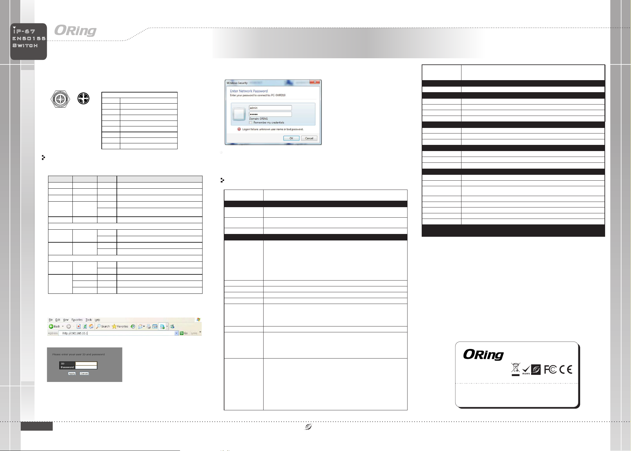
3. After logging in, you should see the following screen. For more information on
configurations, please refer to the user manual. For information on operating the device
using ORing’s Open-Vision management utility, please go to ORing website.
Version 1.0
10/100/1000Base-T(X) M12 port with X-Coding
Pin No. Description
#1 BI_DA+
#2 BI_DA-
#3 BI_DB+
#4 BI_DB-
#5 BI_DD+
#6 BI_DD-
#7 BI_DC-
#8 BI_DC+
8-Pin Gigabit Port Definition
LED
Color
Status
Description
PWR1 Green On DC power module 1 activated
PWR2 Green On DC power module 2 activated
R.M Green On Device operating in Ring Master mode
Ring Green
On Ring enabled
Blinking Ring structure is broken
Fault Amber On Errors occur (i.e. power failure or port malfunctioning)
10/100Base-T(X) Ethernet ports
LNK/ACT Green On Port is linked
Blinking Transmitting data
Speed Amber On Port is running at 100Mbps
Off Port is running at 10Mbps
10/100/1000Base-T(X) Ethernet ports
LNK/ACT Green On Port is linked
Blinking Transmitting data
Speed
Green On Port is running at 1000Mbps
Amber On Port is running at 100Mbps
Green/Amber Off Port is running at 10Mbps
1. Launch the Internet Explorer and type in IP address of the device. The default static
IP address is 192.168.10.1
Follow the steps below to log in and access the system:
2. Log in with default user name and password (both are ).admin
Power
Input Po wer
Powe r Co nsumption(Typ.)
Du al 24V DC ( power ra ti ng : 16 .8 ~3 0V DC ) on d ua l 4- pi n ma le S -c od in g co nn ec to r
20 Watts
Reset Function
Rese t Bu tton < 5 se c: S ys te m re bo ot , > 5 se c: Factory default
Overload Current Protec tion
Revers e Polarity P ro tection
Present
Present
ORing Switch Model
10/100 Base-T(X) Ports in
M12 Auto MDI/MDIX 12 (4-pin fem ale D-coding)
Physical Ports
Technology
Ethernet Standard s
IEEE 802.3 for 10Base -T
IEEE 802.3u for 100Base -TX
IEEE 802.3ab for 1000 Ba se -T
IEEE 802.3x for Flow co nt rol
IEEE 802.3ad for LACP ( Li nk A ggregation Contro l Pr otocol)
IEEE 802.1p for COS (Cl as s of Service)
IEEE 802.1Q for VLAN Tagging
IEEE 802.1w for RSTP (Rapid Spa nn ing Tree Pr ot ocol)
IEEE 802.1s for MSTP (M ul tiple Spanning Tree Protocol)
IEEE 802.1x for Authent ic ation
IEEE 802.1AB for LLDP (Li nk L ay er D iscovery Protocol)
8k
MAC Table
8
Priority Queues
TES-W9124 GT-M12X-BP2-24V-IP54
10/100/1000Base -T( X) p orts
in M12 4 (8-pin fema le X-coding with 2xbypass functio n included)
RS-232 Serial Conso le Port RS-232 in M12 c onnector (female A-coding). Baud rate s etting: 115 200bps, 8, N, 1
Store-and-Forward
Processing
Sw itch Properties
Sw itching latency: <7 µs
Sw itching bandwidth: 10 .4 Gbps
Throughput (packet per se co nd): 7.738Mpps@64 By tes packet
Max. Number of Ava ilable VLANs: 4095
IGMP multicast grou ps : 128 for each VLAN
Port rate limi ti ng: User Define
Security Features
Device Binding securi ty f eature
Enable/disable po rt s, MAC based port securit y
Port b as ed network access contr ol ( 802.1x)
VLAN (802.1Q) to segr eg ate and secure network traffi c
Radi us c entralized password manag em ent
SNMPv3 encrypted au th entication and access s ec urity
Https / SSH enhance network s ec urity
Software Fea tures
STP/RSTP/MSTP (IE EE 8 02.1D/w/s)
Redu nd ant Ring (O-Ring) wit h re cove ry t ime less than 10/30ms over 250 un it s
. Fast Ethernet po rt s supports less 10ms mi ll iseconds recovery timeNOTE 1
Gigabit Ethernet po rt s supports less 30ms mill is econds recovery timeNOTE 2.
TOS/ Di ffserv supported
Quality of Service (802 .1 p) for real-time traffic
VLAN (802.1Q) with VLAN t ag ging and GVRP support ed
IGMP Snooping
IP-based bandwidt h ma nagement
Application-bas ed Q oS management
DOS/DDOS auto preventio n
Port c on figura tion, status, stati st ics, monitoring, se cu rity
DHCP Server/Client/Relay
SMTP Client
Modbus TCP
Network Redundancy
O-Ring
O-Chain
MRP*NOTE
MSTP (RSTP/STP comp at ible)
4Mbits
Packet Buf fe r Size
Up to 9.6K Bytes
Jumbo Frame
Physical Chara cteristic
Enclosure IP-54
Dimension (W x D x H) 280 (W) x 90 (D) x 182 (H) mm (11.02 x 3.54 x 7.17 inch.)
Weight (g) 32 15 g
Environmenta l
-40 to 85 C (-40 to 185 F)
o o
Storage Temperature
5% t o 95 % Non-condensing
Operating Humidity
Regulatory App rovals
EN 55032, CISPR32, EN 61000-3-2, EN 61000-3-3, FCC Par t 15 B c la ss A
EMI
EN 55035 (IEC/EN 61000-4-2 (ESD), IEC/EN 61000-4-3 (RS), IEC/EN 61000-4-4 (EFT),
IEC/EN 61000-4-5 (Surge), IEC/EN 61000-4-6 (CS), IEC/EN 61000-4-8(PFMF), IEC/EN 61000-4-11 (DIP))
EMS
IEC60068-2-27
Shock
IEC60068-2-31
IEC60068-2-6
Vibration
Free Fall
MTBF
17 7,214 hrs
EN 62368-1 (LVD)
Safety
-40 to 75 C (-40 to 167 F)
o o
Operating Tempe rature
*Note: This function is available by request only.
CE EMC (EN 55035, EN 55032), FCC Part 15 B, EN 50155(EN 50121-1, EN 50121-3-2)
EMC
EN 50155(IEC 61373)
Other
Warranty
5 ye ar s
TES-W9124GT-M12X-BP2-24V-IP54
TES-W9124GT-M12X-BP2
-24V-IP54
EN50155 Industrial IP-54 managed
Ethernet switch
S w i tc h
E N 5 0 1 5 5
I N D U S T R I A L
I P - 6 7

Other ORiNG Switch manuals

ORiNG IGPS-1082GP Series User manual

ORiNG

ORiNG IGPS-1082GP Series User manual

ORiNG IGS-P9164 Series User manual

ORiNG

ORiNG IGS-P9164 Series User manual

ORiNG IGPS-1080A User manual

ORiNG

ORiNG IGPS-1080A User manual

ORiNG IGPS-9822DGP+ User manual

ORiNG

ORiNG IGPS-9822DGP+ User manual

ORiNG IDS-342GT User manual

ORiNG

ORiNG IDS-342GT User manual

ORiNG IES-180-L User manual

ORiNG

ORiNG IES-180-L User manual

ORiNG IGS-9848GPF User manual

ORiNG

ORiNG IGS-9848GPF User manual

ORiNG IGPS-9042GP-24V User manual

ORiNG

ORiNG IGPS-9042GP-24V User manual

ORiNG TPS-1080-M12 User manual

ORiNG

ORiNG TPS-1080-M12 User manual

ORiNG TGPS-9084GT-M12 User manual

ORiNG

ORiNG TGPS-9084GT-M12 User manual

ORiNG RGS-7244GP User manual

ORiNG

ORiNG RGS-7244GP User manual

ORiNG RGS-R9004GP+ME-HV User manual

ORiNG

ORiNG RGS-R9004GP+ME-HV User manual

ORiNG IES-2050A User manual

ORiNG

ORiNG IES-2050A User manual

ORiNG IGS-9084GP-FB2-SS User manual

ORiNG

ORiNG IGS-9084GP-FB2-SS User manual

ORiNG IGPS-R9084GP User manual

ORiNG

ORiNG IGPS-R9084GP User manual

ORiNG IGPS-1042GPA User manual

ORiNG

ORiNG IGPS-1042GPA User manual

ORiNG RES-3242GC User manual

ORiNG

ORiNG RES-3242GC User manual

ORiNG TPS-3162GT-M12-BP1 User manual

ORiNG

ORiNG TPS-3162GT-M12-BP1 User manual

ORiNG RGPS-R9244GP+-P Series User manual

ORiNG

ORiNG RGPS-R9244GP+-P Series User manual

ORiNG TES-250-M12 User manual

ORiNG

ORiNG TES-250-M12 User manual

ORiNG TPS-W9124GT-M12X-BP2 -24V-IP54 User manual

ORiNG

ORiNG TPS-W9124GT-M12X-BP2 -24V-IP54 User manual

ORiNG IPS-1080A User manual

ORiNG

ORiNG IPS-1080A User manual

ORiNG IGPS-1411GTPA User manual

ORiNG

ORiNG IGPS-1411GTPA User manual

ORiNG TGPS-9164GT-M12X-BP2-24V User manual

ORiNG

ORiNG TGPS-9164GT-M12X-BP2-24V User manual

Popular Switch manuals by other brands

Murphy EVS-A Specification sheet

Murphy

Murphy EVS-A Specification sheet

H3C S7500E-XS Series Configuration guide

H3C

H3C S7500E-XS Series Configuration guide

Spaun Electronic SMS 9982 NF manual

Spaun Electronic

Spaun Electronic SMS 9982 NF manual

CYP CPRO-3D41GAME Operation manual

CYP

CYP CPRO-3D41GAME Operation manual

Asante IntraCore IC3624PWR Specifications

Asante

Asante IntraCore IC3624PWR Specifications

Airlink101 ASW324V2 Quick installation guide

Airlink101

Airlink101 ASW324V2 Quick installation guide

MOOG ANIMATICS Combitronic DS2020 Installation and start-up manual

MOOG ANIMATICS

MOOG ANIMATICS Combitronic DS2020 Installation and start-up manual

3Com SuperStack 4 3C16465B user guide

3Com

3Com SuperStack 4 3C16465B user guide

koban KME quick start guide

koban

koban KME quick start guide

Hubsat HubSat8DiV installation guide

Hubsat

Hubsat HubSat8DiV installation guide

HDanywhere mHub 2K PoE manual

HDanywhere

HDanywhere mHub 2K PoE manual

S&C Alduti-Rupter instruction sheet

S&C

S&C Alduti-Rupter instruction sheet

Festo PEV-1/4-B-OD operating instructions

Festo

Festo PEV-1/4-B-OD operating instructions

H3C S5590-HI Series manual

H3C

H3C S5590-HI Series manual

steute KF Mounting and wiring instructions

steute

steute KF Mounting and wiring instructions

Lindy 32529 user manual

Lindy

Lindy 32529 user manual

NETGEAR GS108X installation guide

NETGEAR

NETGEAR GS108X installation guide

Sontay RF-LW-HUB manual

Sontay

Sontay RF-LW-HUB manual

manuals.online logo
manuals.online logoBrands
  • About & Mission
  • Contact us
  • Privacy Policy
  • Terms and Conditions

Copyright 2025 Manuals.Online. All Rights Reserved.