manuals.online logo
Brands
  1. Home
  2. •
  3. Brands
  4. •
  5. ORiNG
  6. •
  7. Switch
  8. •
  9. ORiNG TPS-3162GT-M12-BP1 User manual

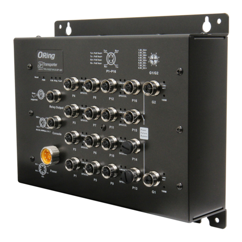
ORiNG TPS-3162GT-M12-BP1 User manual

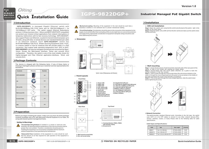
Quick Installation Guide
Version 1.0
Quick Installation Guide
Introduction
PRINTED ON RECYCLED PAPER
QIG
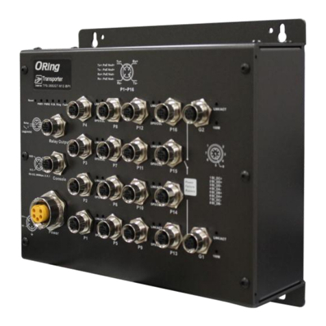
The series, including the
model, managed Ethernet switch
designed for industrial applications, such as rolling stock, vehicle, and
railway applications. The series boasts EN50155 compliance and M12
connectors to ensure tight and robust connections, and guarantee
reliable operation against environmental disturbances, such as vibration
and shock. All models feature sixteen 10/100Base-T(X) P.S.E. ports which
are able to provide sufficient power for power-hungry devices. Therefore, you
can attach an IEEE 802.3af-compliant device to the switch without requiring
additional power. The series also provides 1 set of bypass ports that
ensure constant network connectivity if power outage or node failure
occurs. In such situations, the device will bypass the inactive switch and
continue to transfer network traffic to the next switch in the relay.
TPS-3162GT-M12-BP1
TPS-3162GT-M12-BP1-24V are
TPS-3162GT-M12-BP1
and
Package Contents
Installation
Wall-mount
The device can be fixed to the wall. Follow the steps below to install the device on the wall.
Hold the evice upright against the wall
Insert four screws through the large opening of the keyhole-shaped apertures at the
top and bottom of the unit and fasten the screw to the wall with a screwdriver.
Slide the evice downwards and tighten the four screws for added stability.
Step 1:
Step 2:
Step 3:
d
d
The series is shipped with the following items. If any
of these items is missing or damaged, please contact your customer service
representative for assistance.
TPS-3162GT-M12-BP1
Preparation
Before you begin installing the device, make sure you have all of the package
contents available and a PC with Microsoft Internet Explorer 6.0 or later, for
using web-based system management tools.
Elevated Operating Ambient:
Reduced Air Flow:
Mechanical Loading:
Circuit Overloading:
If installed in a closed environment, make sure
the operating ambient temperature is compatible with the maximum
ambient temperature (Tma) specified by the manufacturer.
Make sure the amount of air flow required for safe operation
of the equipment is not compromised during installation.
Make sure the mounting of the equipment is not in a
hazardous condition due to uneven mechanical loading.
Consideration should be given to the connection of the
equipment to the supply circuit and the effect that overloading of the circuits
might have on overcurrent protection and supply wiring. Appropriate
consideration of equipment nameplate ratings should be used when addressing
this concern.
Safety & Warnings
For pin assignments of power, console and relay output ports, please refer to the following tables.
Contents
TPS-3162GT-M12-BP1/
TPS-3162GT-M12-BP1-24V
Pictures Number
1
CD 1
Dimension
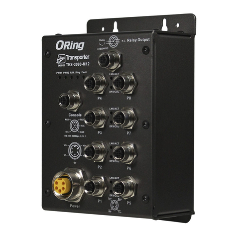
Panel Layouts
Front View
1. Reset button
2. Power1 status LED
3. Power2 status LED
4. R.M. status LED
5. Ring status LED
6. Fault LED
7. Relay output port
8. Console port
9. Power connector
10. PoE Fast Ethernet ports
11. LNK/ACT indicator for PoE Fast Ethernet
port
12. PoE status LED for PoE Fast Ethernet ports
13. Duplex/collision indicator for
PoE Fast Ethernet port
14.
15.
16.
Gigabit Ethernet ports
LNK/ACT indicator for Gigabit Ethernet
port
Speed indicator for Gigabit Ethernet port
Wiring
Grounding
Grounding and wire routing help limit the effects of noise due to electromagnetic interference
(EMI). Run the ground connection from the grounding pin on the power connector to the grounding
surface prior to connecting devices.
Power port pinouts
The device supports two sets of power supplies and uses the M23 5-pin
female connector on the front panel for the dual power inputs.
Insert a power cable to the power connector on the device.
Rotate the outer ring of the cable connector until a snug fit is
achieved. Make sure the connection is tight.
Step 1:
Step 2:
V1+
V1-
V2+
V2-
Relay output port pinouts
Relay N.C.
3A@24VDC
Network Connection
The switch has sixteen 10/100Base-T(X) and two 10/100/1000Base-T(X) Ethernet ports in the form
of M12 connector. Depending on the link type, the switch uses CAT 3, 4, 5,5e UTP cables to
connect to network devices (PCs, servers, switches, routers, or hubs). Please refer to the
following table for cable specifications.
4-Pin PoE Port Definition
TPS-3162GT-M12-BP1
TPS-3162GT-M12-BP1 1907-2-29-TPS3162GTBP1-1.0
Switch
EN50155
EN50155 18-port managed
PoE Ethernet switch
INDUSTRIAL
1
Instead of screwing the screws in all the way, it is advised to
leave a space of about 2mm to allow room for sliding the
switch between the wall and the screws.
The switch uses the M12 A-coded 5-pin male connector on
the front panel for relay output. Use a power cord with an
M12 A-coded 5-pin female connector to connect the relay.
The relay contacts will detect user-configured events and
form an open circuit when an event is triggered.
Cable Type Max. Length Connector
10BASE-T Cat. 3, 4, 5 1 00-ohm UTP 100 m ( 328 ft) 4-pin female M12
D-coding connector
100BASE-TX Cat. 5 100-ohm UTP UTP 100 m (328 ft) 4-pin female M12
D-coding connector
1000BASE-T Cat. 5/Cat. 5e 100-ohm UTP UTP 1 00 m (328 ft)
8-pin female M12
A-coding connector
For pin assignments of the LAN ports, please refer to the following tables.
QIG 1
2
Tx+
1
Rx+
Tx-
4
Rx-
3
8-Pin Gigabit Port Definition
M12 Pin Description
Pin No. Description
#1 BI_DC +
#2 BI_DD +
#3 BI_DD-
#4 BI_DA -
#5 BI_DB+
#6 BI_DA+
#7 BI_DC-
#8 BI_DB -
7
8
9
11
13
16
15
14
Console port pinouts
N.C.
RXD
RS-232, 9600bps, 8, N, 1
GND
TXD
N.C.
4
5
6
7
8
21
3
FaultRingR.M.PWR2PWR1
Reset
3A@24VDC
Relay N.C.
RelayOutput
Console
N.C.
RXD
RS-232,9600bps,8, N, 1
GND
TXD
N.C.
Power P1
LNK/ACT
DPX/COL
P2
LNK/ACT
DPX/COL
P3
LNK/ACT
DPX/COL
P4
LNK/ACT
DPX/COL
P9
LNK/ACT
DPX/COL
P10
LNK/ACT
DPX/COL
P11
LNK/ACT
DPX/COL
P12
LNK/ACT
DPX/COL
P5
P6
P7
P8
P13
P14
P15
P16
V1+
V1-
V2+
V2-
G2
LNK/ACT
100M
G1
LNK/ACT
100M
Power
Failure
Bypass
4
5
6
7
8
21
1BI_DC+
2BI_DD+
3BI_DD-
4BI_DA-
5BI_DB+
6BI_DA+
7BI_DC-
8BI_DB-
Tx+ Rx+
Tx-Rx-
P1~P16
3
Tx+:PoEVout+
Tx-:PoE Vout+
Rx+:PoEVout-
Rx-:PoE Vout-
TPS-3162GT-M12-BP1
PoE
PoE
PoE
PoE
PoE
PoE
PoE
PoE
FaultRingR.M.PWR2PWR1
Reset
3A@24VDC
Relay N.C.
Relay Output
Console
N.C.
RXD
RS-232,9600bps, 8, N, 1
GND
TXD
N.C.
Power P1
LNK/ACT
DPX/COL
P2
LNK/ACT
DPX/COL
P3
LNK/ACT
DPX/COL
P4
LNK/ACT
DPX/COL
P9
LNK/ACT
DPX/COL
P10
LNK/ACT
DPX/COL
P11
LNK/ACT
DPX/COL
P12
LNK/ACT
DPX/COL
P5
P6
P7
P8
P13
P14
P15
P16
V1+
V1-
V2+
V2-
G2
LNK/ACT
100M
G1
LNK/ACT
100M
Power
Failure
Bypass
4
5
6
7
8
21
1BI_DC+
2BI_DD+
3BI_DD-
4BI_DA-
5BI_DB+
6BI_DA+
7BI_DC-
8BI_DB-
Tx+ Rx+
Tx-Rx-
P1~P16
3
Tx+:PoE Vout+
Tx-: PoE Vout+
Rx+:PoE Vout-
Rx-: PoE Vout-
TPS-3162GT-M12-BP1
PoE
PoE
PoE
PoE
PoE
PoE
PoE
PoE
10
12
Pin No. Description
#1 RD+ with PoE power input -
#2 TD+ with P oE power input +
#3 RD- with PoE power input -
#4 TD- wit h PoE power input +
4 5 62 3
QIG Quick Installation Guide
PRINTED ON RECYCLED PAPER
Quick Installation Guide
ORing Industrial Networking Corp.
Copyright© 2014 ORing
All rights reserved.

TEL: +886-2-2218-1066
FAX: +886-2-2218-1014
Website: www.oring-networking.com
E-mail: [email protected]
Version 1.0
QIG
Specifications
Switch
EN50155
INDUSTRIAL
1. Launch the Internet Explorer and type in IP address of the device. The default static
IP address is 192.168.10.1
Follow the steps below to log in and access the system:
2. Log in with default user name and password (both are ).admin
3. After logging in, you should see the following screen. For more information on
configurations, please refer to the user manual. For information on operating the device
using ORing’s Open-Vision management utility, please go to ORing website.
Resetting
To restore the device configurations back to the factory defaults, press the button for a
few seconds. Once the power indicator starts to flash, release the button. The device will then
reboot and return to factory defaults.
Reset
Configurations
After installing the and connecting cables, start the evice by
turning on power. The green power LED should turn on. Please refer to the
following tablet for LED indication.
switch d
TPS-3162GT-M12-BP1
TPS-3162GT-M12-BP1
EN50155 18-port managed
PoE Ethernet switch
LED Color Statu s Descr ip tion
PWR1 Green On DC power module 1 activ ated
PWR2 Green On DC power module 2 activ ated
R.M Green On System runn ing i n Ring Mast er mode
Ring Green On SystemrunninginRingmode
Faul t Amber On Errors occur (power f ail ure or port lin k down)
10/100Base-T(X) Ports
On Port is linked
LNK/ACT Green
Blinking Transmitting data
PoE Green On Port providing power to PD
On Port running in f ull-duplex mode
DPX/ COL Amber
Blinking Collision occurs
10/100/ 1000Base-T Po rts
On Port is linked
LNK/ACT Green
Blinking Transmitting data
100M Amber On Port speed at 10 0M
Power
Redundant Input Power
Power Consumption(Typ.)
Dual DC inputs. 48VDC on 5-pin M23 connector
14.88 Watts (power consumption of P.S.E. is not included)
Physical Characteristic
Enclosure IP-40
Dimension(WxDxH) 260(W) x 91.3(D) x 216(H) mm (10.24 x 3.59 x 8.5 inch.)
Weig ht ( g) 2104 g
Environmental
-40to85 C(-40to185F)
oo
Storage Temperature
5% to 95% Non-condensing
Operating Humidity
Regulatory Approvals
FCC Part 15, CISPR (EN55022) class A, EN50155 (EN50121-3-2, EN55011, EN50121-4)
EMI
EN61000-4-2 (ESD), EN61000-4-3 (RS), EN61000-4-4 (EFT), EN61000-4-5 (Surge),
EN61000-4-6 (CS), EN61000-4-8, EN61000-4-11
EMS
IEC60068-2-27
Shock
IEC60068-2-32
IEC60068-2-6
Vibration
Free Fall
Warranty
5 years
EN60950-1
Safety
Fault Contact
Relay Relay output to carry capacity of 3A at 24VDC on M12 connector (5-pin M12 A-coding)
Overload Current Protection
Reverse Polarity Protection
Present
Not Presented
-40to70 C(-40to158F)
oo
Operating Temperature
ORing Switch Model
10/100 Base-T(X) Ports in
M12AutoMDI/MDIXwith
P. S . E .
16xM12connector(4pinD-coding)
Physical Ports
Technology
Ethernet Standards
IEEE 802.3 for 10Base-T
IEEE 802.3u for 100Base-TX
IEEE 802.3ab for 1000Base-T
IEEE 802.3x for Flow control
IEEE 802.3ad for LACP (Link Aggregation Control Protocol)
IEEE 802.1D for STP (Spanning Tree Protocol)
IEEE 802.1p for COS (Class of Service)
IEEE 802.1Q for VLAN Tagging
IEEE 802.1w for RSTP (Rapid Spanning Tree Protocol)
IEEE 802.1s for MSTP (Multiple Spanning Tree Protocol)
IEEE 802.1x for Authentication
IEEE 802.1AB for LLDP (Link Layer Discovery Protocol)
IEEE 802.3af PoE specification (up to 15.4 Watts per port for P.S.E.)
8192 MAC addresses
MAC Table
4
Priority Queues
TPS-3162GT-M12-BP1
10/100/1000Base-T(X) ports
in M12 2 x M12 connector (8-pin A-coding)
RS-232 Serial Console Port RS-232 in M12 connector (5-pin A-coding). Baud rate setting: 9600bps, 8, N, 1
Store-and-Forward
Processing
Switch Properties
Switching latency: 7 us
Switching bandwidth: 7.2 Gbps
Max. Number of Available VLANs: 4096
IGMP multicast groups: 1024
Port rate limiting: User Define
Security Features
Enable/disable ports, MAC based port security
Port based network access control (802.1x)
VLAN (802.1Q) to segregate and secure network traffic
Supports Q-in-Q VLAN for performance & security to expand the VLAN space
Radius centralized password management
SNMP v1/v2c/v3 encrypted authentication and access security
Software Features
STP/RSTP/MSTP (IEEE 802.1D/w/s)
Redundant Ring (O-Ring) with recovery time less than 10ms over 250units
TOS/Diffserv supported
Quality of Service (802.1p) for real-time traffic
VLAN (802.1Q) with VLAN tagging and GVRP supported
IGMP Snooping for multicast filtering
Port configuration, status, statistics, monitoring, security
SNTP for synchronizing of clocks over network
Support PTP Client (Precision Time Protocol) clock synchronization
DHCP Server / Client support
Port Trunk support
MVR (Multicast VLAN Registration) support
Modbus TCP
Network Redundancy
O-Ring
Open-Ring
O-Chain
MRP
STP/RSTP/MSTP
Warning / Monitoring System
Relay output for fault event alarming
Syslog server / client to record and view events
Include SMTP for event warning notification via email
Event selection support
TPS-3162GT-M12-BP1-24V
Dual DC inputs. 24 (12~57VDC) VDC on 5-pin M23
connector
PoE Output Power 240 Watts 120 Watts (12~24VDC) / 240 Watts (24~57VDC)
※Please see details in the user manual section 2.4.
2220 g

This manual suits for next models

1

Other ORiNG Switch manuals

ORiNG RGS-7244GP User manual

ORiNG

ORiNG RGS-7244GP User manual

ORiNG IES-1050A User manual

ORiNG

ORiNG IES-1050A User manual

ORiNG IGS-9848GPF User manual

ORiNG

ORiNG IGS-9848GPF User manual

ORiNG IGPS-1082GP Series User manual

ORiNG

ORiNG IGPS-1082GP Series User manual

ORiNG TPS-3882GT-M12-BP1 User manual

ORiNG

ORiNG TPS-3882GT-M12-BP1 User manual

ORiNG IGS-9168GP series User manual

ORiNG

ORiNG IGS-9168GP series User manual

ORiNG IPS-1080-24V User manual

ORiNG

ORiNG IPS-1080-24V User manual

ORiNG IES-2050A User manual

ORiNG

ORiNG IES-2050A User manual

ORiNG IGS-9812GP User manual

ORiNG

ORiNG IGS-9812GP User manual

ORiNG IES-180-L User manual

ORiNG

ORiNG IES-180-L User manual

ORiNG IGPS-9822DGP+ User manual

ORiNG

ORiNG IGPS-9822DGP+ User manual

ORiNG TGPS-9168GT-M12 User manual

ORiNG

ORiNG TGPS-9168GT-M12 User manual

ORiNG IPS-2042 Series User manual

ORiNG

ORiNG IPS-2042 Series User manual

ORiNG TRGPS-9084GT-M12X-BP2-MV User manual

ORiNG

ORiNG TRGPS-9084GT-M12X-BP2-MV User manual

ORiNG IPS-3082GC-24V User manual

ORiNG

ORiNG IPS-3082GC-24V User manual

ORiNG TGPS-9164GT-M12X-BP2-24V User manual

ORiNG

ORiNG TGPS-9164GT-M12X-BP2-24V User manual

ORiNG DGS-9168GP-SS-AIO_S User manual

ORiNG

ORiNG DGS-9168GP-SS-AIO_S User manual

ORiNG TRGPS-9084TG-M12X-BP2-MV User manual

ORiNG

ORiNG TRGPS-9084TG-M12X-BP2-MV User manual

ORiNG IGPS-1080-24V User manual

ORiNG

ORiNG IGPS-1080-24V User manual

ORiNG IGPS-1041GTA User manual

ORiNG

ORiNG IGPS-1041GTA User manual

ORiNG IES-2060 Series User manual

ORiNG

ORiNG IES-2060 Series User manual

ORiNG IGPS-1042GPA User manual

ORiNG

ORiNG IGPS-1042GPA User manual

ORiNG GS-9164GF Series User manual

ORiNG

ORiNG GS-9164GF Series User manual

ORiNG IBS-102FX Series User manual

ORiNG

ORiNG IBS-102FX Series User manual

Popular Switch manuals by other brands

Scion-Tech SC01.7050 user manual

Scion-Tech

Scion-Tech SC01.7050 user manual

Juniper QFX5200-48Y quick start guide

Juniper

Juniper QFX5200-48Y quick start guide

H3C S5830V2 series Configuration guide

H3C

H3C S5830V2 series Configuration guide

DANLERS CESRA PIR 10VDC Installation notes

DANLERS

DANLERS CESRA PIR 10VDC Installation notes

iotty E2S PLUS manual

iotty

iotty E2S PLUS manual

Honeywell 5869 quick start guide

Honeywell

Honeywell 5869 quick start guide

Magnimage V8 Series user manual

Magnimage

Magnimage V8 Series user manual

Intellinet 508827 instructions

Intellinet

Intellinet 508827 instructions

DANLERS CEFLA PIR DALIP Installation notes

DANLERS

DANLERS CEFLA PIR DALIP Installation notes

Dell N2000 Series Firmware upgrade

Dell

Dell N2000 Series Firmware upgrade

Axis Dome Intrusion Switch C installation guide

Axis

Axis Dome Intrusion Switch C installation guide

Eaton XNH00-A160 Series Instruction leaflet

Eaton

Eaton XNH00-A160 Series Instruction leaflet

Cabletron Systems 9G421-02 Appendix

Cabletron Systems

Cabletron Systems 9G421-02 Appendix

Barksdale KD1 Series operating instructions

Barksdale

Barksdale KD1 Series operating instructions

AYRSTONE AyrMesh Hub Setup manual

AYRSTONE

AYRSTONE AyrMesh Hub Setup manual

Cisco MS420-24 installation guide

Cisco

Cisco MS420-24 installation guide

RDL RACK-UP Series quick start guide

RDL

RDL RACK-UP Series quick start guide

Juniper QFX10002 Hardware guide

Juniper

Juniper QFX10002 Hardware guide

manuals.online logo
manuals.online logoBrands
  • About & Mission
  • Contact us
  • Privacy Policy
  • Terms and Conditions

Copyright 2025 Manuals.Online. All Rights Reserved.