manuals.online logo
Brands
  1. Home
  2. •
  3. Brands
  4. •
  5. ORiNG
  6. •
  7. Switch
  8. •
  9. ORiNG IES-3162GC Series User manual

ORiNG IES-3162GC Series User manual

IES-3162GC
10/ 100 M
P7
P5
P3
P1
P8
P6
P4
P2
P15
P13
P11
P9
P16
P14
P12
P10
G2
G2 LNK /AC T
Gig abit Co mbo
G1
G2 LNK /AC T
PWR
PWR 1
PWR 2
Quick Installation Guide
Introduction
PRINTED ON RECYCLED PAPER
is managed Redundant Ring Ethernet switch with 16x10/100Base-T(X)IES-3162GC
ports and 2xgigabit combo ports. With completely support of Ethernet Redundancy
protocol, O-Ring (recovery time < 10/30ms over 250 units of connection), O-Chain,
MRP and MSTP/RSTP/STP (IEEE 802.1s/w/D) can protect your mission-critical*NOTE
applications from network interruptions or temporary malfunctions with its fast recovery
technology. O-Chain is the revolutionary network redundancy technology that provides
the add-on network redundancy topology for any backbone network, O-Chain allows
multiple redundant network rings of different redundancy protocols to join and function
together as a larger and more robust compound network topology. O-Chain providing
ease-of-use while maximizing fault-recovery swiftness, flexibility, compatibility, and
cost-effectiveness in one set of network redundancy topology. All function of IES-
3162GC can be managed centralized and convenient by a powerful windows utility —
Open-Vision. In addition, the wide operating temperature range from -40 to 75 C can
o
satisfy most of operating environment. Therefore, the switch is one of the most reliable
choice for highly-managed and Fiber Ethernet application.
Preparation
Before you begin installing the switch, make sure you have all of the package
contents available and a PC with Microsoft Internet Explorer 6.0 or later, for
using web-based system management tools.
Elevated Operating Ambient: If installed in a closed or multi-unit rack
assembly, the operating ambient temperature of the rack environment may be
greater than room ambient. Therefore, consideration should be given to
installing the equipment in an environment compatible with the maximum
ambient temperature (Tma) specified by the manufacturer.
Reduced Air Flow: Installation of the equipment in a rack should be such
that the amount of air flow required for safe operation of the equipment is
not compromised.
Safety & Warnings
Dimension
Panel Layouts
1. Power LED
2. PWR1 LED
3. PWR2 LED
4. R.M. status LED
5. Ring status LED
6. Faulty relay indicator
7. Console port
8. Link/Act LED for Ethernet port
9. Full/Half-duplex indicator
10. LAN ports
11. Link/Act LED for SFP ports
12. Combo ports
13. Reset button
14. Link/Act LED for Gigabit port
15. 100Mbps indicator for Gigabit port
Package Contents
Contents
DIN-rail Kit
CD
IES-3162GC
Pictures Number
X 1
X 1
X 1
Front View
Top Panel
The device is shipped with the following items. If any of these items is
missing or damaged, please contact your customer service representative for
assistance.
QIG
Console Cable
X 2
X 1
X 1
Wall-mount Kit
7
1
2
3
4
5
6
Rear View
12
1
1. Wall-mount screw holes
2. Din-rail screw holes
2
1. Terminal blocks: PWR1,
PWR2 (12 48V DC), Relay-
2. Ground wire.
1
Installation
Step 1: Slant the switch and screw the Din-rail kit onto the back of the switch, right in
the middle of the back panel.
Step 2: Slide the switch onto a DIN-rail from the Din-rail kit and make sure the switch
clicks into the rail firmly.
DIN-rail Installation
Step 1: Screw the two pieces of wall-mount kits onto both ends of the rear panel of the
switch. A total of six screws are required, as shown below.
Step 2: Use the switch, with wall mount plates attached, as a guide to mark the
correct locations of the four screws.
Step 3: Insert a screw head through the large parts of the keyhole-shaped apertures,
and then slide the switch downwards. Tighten the screws for added stability.
Wall-mounting
Q I G IES-3162GC 1907-200-E3162GCXX2-FX011
Mechanical Loading: Mounting of the equipment in the rack should be such that
a hazardous condition is not achieved due to uneven mechanical loading.
Circuit Overloading: Consideration should be given to the connection of the equipment
to the supply circuit and the effect that overloading of the circuits might have on
overcurrent protection and supply wiring. Appropriate consideration of equipment
nameplate ratings should be used when addressing this concern.
Network Connection
The switch provides standard Ethernet ports. According to the link type, the switch uses
CAT 3,4,5,5e UTP cables to connect to any other network devices (PCs, servers,
switches, routers, or hubs). Please refer to the following table for cable
specifications.
Cable Types and Specifications:
Cable Type Max. Length Connector
10BASE-T Cat. 3, 4, 5 100-ohm UTP 100 m (328 ft) RJ-45
100BASE-TX Cat. 5 100-ohm UTP UTP 100 m (328 ft) RJ-45
1000BASE-T Cat. 5 / Cat. 5e 100-ohm UTP UTP 100 m (328 ft) RJ-45
10
8
9
IES-3162GC
Version 2.1
154.0
96.4
13
12
PWR -1PWR -2
1A@ 24V
DC 50 -57V
V2- V 2+ V1- V 1+
Fault
Unit =mm (Tolerance ±0.5mm)
108.5
88.0
48.3
17.5
94.0
124.0
48.0
58.0
7.50
Ø5.0 0
Ø8.0 0
80.5 0
62.0
87.9
40.0
15.5
14.5
49.67
Ø4.0 0
Ø4.0 0
Industrial Managed Ethernet Switch
S W I T C H
I N D U S T R I A L
*NOTE : This function is available by request only.
IES-3162GC
10/10 0M
P7
P5
P3
P1
P8
P6
P4
P2
P15
P13
P11
P9
P16
P14
P12
P10
G2
G2 LNK/A CT
Gigab it Comb o
G1
G2 LNK/A CT
PWR
PWR1
PWR2
11
13
The product is open type, intended to be installed in and industrial control panel or an enclosure.
14
15
!
Warning [AVERTISSEMENT]
Take into consideration the following guidelines before wiring the device
[Tenez compte des directrices suivantes avant de câbler l’appareil.]
1. Terminal block is mating with Plug and suitable for 12-24AWG.
Torque value 4.5 lb-in.
[Le bornier est compatible avec les connecteurs et convient pour 12-24AWG.
Valeur de couple 4,5 lb-in.]
2. The temperature rating of the input connection cable should higher than 105°C
[La température de service nominale du câble d’entrée doit être supérieure à 105 °C]
* Indoor use and pollution degree II, it must be wiped with a dry cloth for clean up the
device and label.
* Utilisation en intérieur et degré de pollution II, il faut l'essuyer avec un chiffon sec
pour nettoyer l'appareil et son étiquette.
* Do not block air ventilation holes.
* Ne bouchez pas les orifices de ventilation.
* If the equipment is used in a manner not specified by the manufacturer, the
protection provided by the equipment may be impaired.”
* Si l’appareil est utilise d’une maniere non specifiee par le fabricant, la protection
qu’il apporte peut se voir diminuee.”
* Shall be mounted in the Industrial Control Panel and ambient temperature is not
exceed 75 degree C
* doit être monté dans le panneau de commande industriel et la température ambiante
ne doit pas dépasser 75 degrés C
IES-3162GC
10/10 0M
P7
P5
P3
P1
P8
P6
P4
P2
P15
P13
P11
P9
P16
P14
P12
P10
G2
G2 LNK/ ACT
Gigab it Comb o
G1
G2 LNK/ ACT
PWR
PWR1
PWR2
Q I G Quick Installation Guide
PRINTED ON RECYCLED PAPER
Version 2.1
Quick Installation Guide
Resetting
To reboot the switch, press the button less than 5 seconds.Reset
To restore the switch configurations back to the factory defaults, press the button more than 5Reset
seconds.
Specifications
Configurations
After installing the switch, the green power LED should turn on. Please refer to
the following tablet for LED indication.
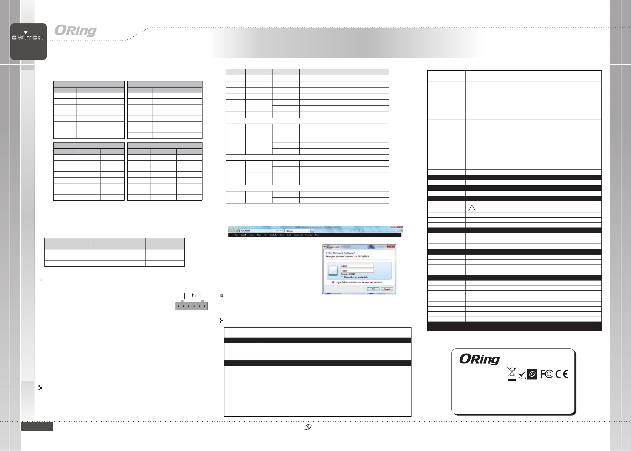
1. Launch the Internet Explorer and type in IP address of the switch. The default static IP address is
192.168.10.1
2. Log in with default user name and password
(both are ). After logging in, you shouldadmin
see the following screen. For more information
on configurations, please refer to the user
manual. For information on operating the switch
using ORing’s Open-Vision management utility,
please go to ORing website.
Follow the steps to set up the switch:
LED
Color
Status
Description
PWR Green On DC power on
PWR1 Green On DC power module 1 activated
PWR2 Green On DC power module 2 activated
R.M Green On Ring Master
Ring Green
On Ring enabled
Blinking Ring structure is broken (i.e. part of the ring is disconnected)
Fault Amber On Faulty relay (power failure or port disconnected)
10/100Base-T(X) Ethernet ports
LNK/ACT
with speed
Green
On Port link up
Blinking Data transmitted
Amber
On Full-duplex mode
Off Half-duplex mode
Blinking Half-duplex mode and collision occurred
10/100/1000Base-T(X) Ethernet ports (Combo port)
LNK/ACT
with speed
Green
On Port link up
Blinking Data transmitted
Amber
On Port link at 100Mbps
Off Port link at 10/1000Mbps
SFP (Combo port)
LNK/ACT Green
On Port link up
Blinking Data transmitted
For pin assignments for different types of cables, please refer to the following
tables.
10/100 Base-T(X) MDI/MDI-X
Pin Number MDI port MDI-X port
1 TD+(transmit) RD+(receive)
2 TD-(transmit) RD-(receive)
3 RD+(receive) TD+(transmit)
4 Not used Not used
5 Not used Not used
6 RD-(receive) TD-(transmit)
7 Not used Not used
8 Not used Not used
Note: “+” and “-” signs represent the polarity of the wires that make up each
wire pair.
To connect the console port to an external management device, you need an RJ-45 to
DB-9 cable, which is also supplied in the package. Below is the console port pin
assignment information.
Console Port Pin Definition
PC (male) pin assignment RS-232 with DB9 (female) pin
assignment (RJ45-DB9 cable) RJ45 pin assignment
PIN#2 RxD PIN#2 RxD PIN#2 RxD
PIN#3 TxD PIN#3 TxD PIN#3 TxD
PIN#5 GND PIN#5 GND PIN#5 GND
Wiring
The switch supports dual redundant power supplies, Power Supply1
(PWR1) and Power Supply 2 (PWR2). The connections for PWR1,
PWR2 and the RELAY are located on the terminal block.
STEP 1: Insert the negative/positive wires into the V-/V+ terminals,
respectively.
STEP 2: To keep the DC wires from pulling loose, use a small flat-
blade screwdriver to tighten the wire-clamp screws on the front of the
terminal block connector.
PWR-1PWR-2
1A@24V
V2- V2+ V1- V1+
Fault
Power inputs
The two sets of relay contacts of the 6-pin terminal block connector are used to detect user-
configured events. The two wires attached to the fault contacts form an open circuit when a
user-configured when an event is triggered. If a user-configured event does not occur, the
fault circuit remains closed.
Relay contact
1000Base-T MDI/MDI-X
Pin Number MDI port MDI-X port
1 BI_DA+ BI_DB+
2 BI_DA- BI_DB-
3 BI_DB+ BI_DA+
4 BI_DC+ BI_DD+
5 BI_DC- BI_DD-
6 BI_DB- BI_DA-
7 BI_DD+ BI_DC+
8 BI_DD- BI_DC-
1000Base-T RJ-45 Port
Pin Number Assignment
1 BI_DA+
2 BI_DA-
3 BI_DB+
4 BI_DC+
5 BI_DC-
6 BI_DB-
7 BI_DD+
8 BI_DD-
10/100 Base-T(X) RJ-45 Port
Pin Number Assignments
1 TD+
2 TD-
3 RD+
4 Not used
5 Not used
6 RD-
7 Not used
8 Not used
Grounding and wire routing help limit the effects of noise due to electromagnetic
interference (EMI). Run the ground connection from the ground screws to the grounding
surface prior to connecting devices.
Grounding
OR i n g S w i t c h M o d e l
Ph y s i c a l P o r t s
Te c h n o l o g y
Et h ernet Sta n dards
10 / 100 Base-T ( X) Port s i n RJ45
Au to MDI/MDI X
RS - 232 Seria l C onsole Port
Gi g a bit combo Po r t in RJ-45
an d S F P
Sw itch Prop e rties
Se c urity Features
En a ble/dis a ble ports , M A C based por t s ecurity
Port base d n e twork acc e ss contro l ( 802.1x)
VL A N (802.1Q ) t o segrega t e and secure n e twork traffic
Su p ports Q-i n -Q VLAN for p e r formanc e & s ecurity t o e xpand the V L AN space
Radius cen t raliz e d passwor d m anagemen t
SN M P V1/V2c/ V 3 encrypt e d a uthenti c ation and a c cess secur i ty
So f tware Features
ST P /RSTP/M S TP (IEEE 802 . 1D/w/s)
Redundan t R ing (O-Ri n g) with rec o very tim e l ess than 10 / 30ms ove r 2 50 units
Fast Et h ernet por t s supports l e ss 10 milli s econds re c overy ti m e.NO T E 1.
. Gi g abit Ethe r net ports s u p ports les s 3 0 millise c onds reco very time .NO T E 2
TOS/Dif f s erv suppo r ted
Qu a lity of Se r v ice (802. 1 p) for real - time tra f fic
VL A N (802.1Q ) w ith VLAN ta g ging and GVR P s upporte d
IG M P Snoopin g f or multic a s t filteri n g
Port conf i g urati o n, status , s t atistic s , monitor i ng, securi ty
SN T P for synch r onizing o f c locks ove r network
Su p port PTP Cl i ent (Prec i s ion Time Pr o tocol) cl o ck synchro n ization
DH C P Server / C l ient supp o rt
Port Tru n k support
MV R ( Multica s t VLAN Re g istra t i on) suppo r t
Mo d bus TCP
Ne t work Re d undancy O-Ring , O - Chain, MR P , MS T P/RSTP/ S TP*N O TE
RS - 232 in RJ45 c o nnector w i t h console c a ble. 9600 b ps, 8, N, 1
IE S - 3 1 6 2 G C
16
2
IE E E 802.3 for 1 0 Base-T
IE E E 802.3u fo r 1 00Base-T X a nd 100Bas e -FX
IE E E 802.3z fo r 1 000Base -X
IE E E 802.3ab f o r 1000Bas e -T
IE E E 802.3x fo r F low contr o l
IE E E 802.3ad f o r LACP (Lin k A ggregati o n Control P r otocol)
IE E E 802.1D fo r S TP (Spann i ng Tree Pr o tocol)
IE E E 802.1p fo r C OS (Class o f S ervice)
IE E E 802.1Q fo r V LAN Tag ging
IE E E 802.1w fo r R STP (Ra p i d Spannin g Tree Pro t ocol)
IE E E 802.1s fo r M STP (Mult i p le Spanni n g Tree Pr o tocol)
IE E E 802.1x fo r A uthenti c ation
IE E E 802.1AB f o r LLDP (Lin k L ayer Dis c overy P r o tocol)
Sw itch late n cy: 2.28 us
Sw itch band w idth: 7.2 G b ps
Th r oughput ( p acket per s e cond):5 . 375Mpps @ 6 4Bytes pa c ket
Ma x . Number of Avail a ble VLANs : 4 096
VL A N ID Rang e : VID 1 to 4095
IG M P multica s t groups: 1 0 2 4
Port rat e l imiting : U ser Defin e
MA C Tabl e 8K
Pr o cessing S t ore-and - Forw a rd
Packet b u f fer 1M b its
En v i r o n m e n t a l
-4 0 t o 85 C (-40 to 18 5 F )
o o
St o rage Tempera ture
Op e ratin g Temperature
5% t o 9 5% Non-co n densingOp e ratin g H umidity
Reg u l a t o r y a p p r ovals
EN 5 5 032, CISP R 32, EN 6100 0 - 3-2, EN 610 0 0-3-3, FC C Part 15 B cl a ss AEM I
EN 5 5 024 (IEC/ E N 61000-4- 2 ( ESD: Cont a ct 4KV, Air 8KV ) , IEC/EN 610 0 0-4-3 (RS : 3 V),
IE C /EN 61000 - 4-4 (EFT Po w er 0.5KV, Sig n al 0.5KV) , I EC/EN 6100 0 -4-5 (Sur g e: Powe r 0 .5KV, RJ45 1K V ),
IE C /EN 61000 - 4-6 (CS: 3V) , I EC/EN 610 0 0-4-8(PF M F), IEC/E N 6 1000-4-1 1 ( DIP))
EM S
IE C 60068-2 - 27Sh o ck
IE C 60068-2 - 31
IE C 60068-2 - 6Vi b ratio n
EN 6 0950-1, U L 61010-1 , U L-61010- 2 -201
Sa f ety
Fr e e Fa l l
MT B F
600504.1569 hrs
-4 0 t o 75 C (-40 to 16 7 F )
o o
Fau l t c o n t a c t
Relay Relay outp u t to carry ca p acity of 1A a t 2 4 VDC
Po w e r
Redundan t I nput powe r
Power cons u mption( Typ.) 1 5Wa t ts, 12-48 V DC/1.2A-0.3A
Ov erload cu r rent prot e c tion
Reverse p o larity p r o tection
Pr e sent
Pr e sent on ter m inal bloc k
Ph y s i c a l C h a r a c teristic
En c losure IP - 30 Aluminu m ( non UL cert i fied)
Di m ension (W x D x H )
Weigh t ( g) 12 2 0 g
Du a l DC input 12 - 48VDC on 6- p in termin a l block
* Su p plied by SE LV s o urce eva l uated by UL 6 1 010-1 or 61 0 10-2-20 1 p ower suppl y o nly.
* Fourni pa r l a source SE LV évaluée un i q uement pa r l 'alimen t ation UL 61 0 10-1 or 6101 0 -2-201.
96 . 4(W)x10 8 .5(D)x15 4 (H) mm (3.8 x 4.27x6. 0 6 inch.)
Pr i ority Que u es 4
Re s e t F u n c t i o n
Reset But t o n < 5 se c : Syste m r eboot, > 5 sec : Fac t ory defau l t
CE E M C (EN 55024 , E N 55032), F C C Part 15 BEM C
Wa r r a n t y
*NOTE : This function is available by request only
IES-3162GC Industrial Managed Ethernet Switch
S W I T C H
I N D U S T R I A L
IES-3162GC
!
Up t o 2 000mOp e ratin g A lttitude
ORing Industrial Networking Corp.
Copyright© 2010 ORing
All rights reserved.
TEL: +886-2-2218-1066
FAX: +886-2-2218-1014
Address 3F No 542 2 Zhongzheng Rd Xindian Dist New: ., . - , ., .,
Taipei City 23148 Taiwan,
Website: www.oringnet.com
E-mail: support@oringnet.com
Contact for maintenance and repair service:

Other manuals for IES-3162GC Series

2

Other ORiNG Switch manuals

ORiNG IGS-9844GPFX Series User manual

ORiNG

ORiNG IGS-9844GPFX Series User manual

ORiNG IGS-9084GP-FB2 User manual

ORiNG

ORiNG IGS-9084GP-FB2 User manual

ORiNG TGPS-9084GT-M12X-BP2-24V User manual

ORiNG

ORiNG TGPS-9084GT-M12X-BP2-24V User manual

ORiNG TGPS-9080-M12A-MV User manual

ORiNG

ORiNG TGPS-9080-M12A-MV User manual

ORiNG TRGPS-9084TG-M12X-BP2-MV User manual

ORiNG

ORiNG TRGPS-9084TG-M12X-BP2-MV User manual

ORiNG TPS-W9124GT-M12X-BP2 -24V-IP54 User manual

ORiNG

ORiNG TPS-W9124GT-M12X-BP2 -24V-IP54 User manual

ORiNG RGS-R9004GP+ME-HV User manual

ORiNG

ORiNG RGS-R9004GP+ME-HV User manual

ORiNG TGPS-9084GT-M12X-BP2-MV User manual

ORiNG

ORiNG TGPS-9084GT-M12X-BP2-MV User manual

ORiNG IES-2050A User manual

ORiNG

ORiNG IES-2050A User manual

ORiNG IGPS-1411GTPA User manual

ORiNG

ORiNG IGPS-1411GTPA User manual

ORiNG TRGPS-9084TG-M12X-BP2-MV User manual

ORiNG

ORiNG TRGPS-9084TG-M12X-BP2-MV User manual

ORiNG RGS-R9004GP+ME-HV User manual

ORiNG

ORiNG RGS-R9004GP+ME-HV User manual

ORiNG IGPS-1041GTA User manual

ORiNG

ORiNG IGPS-1041GTA User manual

ORiNG IES-3160 User manual

ORiNG

ORiNG IES-3160 User manual

ORiNG IGS-3044GC User manual

ORiNG

ORiNG IGS-3044GC User manual

ORiNG TPS-1080-M12 User manual

ORiNG

ORiNG TPS-1080-M12 User manual

ORiNG IGS-9122GPM User manual

ORiNG

ORiNG IGS-9122GPM User manual

ORiNG IPS-3082GC-24V User manual

ORiNG

ORiNG IPS-3082GC-24V User manual

ORiNG EN50155 User manual

ORiNG

ORiNG EN50155 User manual

ORiNG RGPS-R9244GP+-P Series User manual

ORiNG

ORiNG RGPS-R9244GP+-P Series User manual

ORiNG IGS-9084GP-FB2-SS User manual

ORiNG

ORiNG IGS-9084GP-FB2-SS User manual

ORiNG IBS-102FX User manual

ORiNG

ORiNG IBS-102FX User manual

ORiNG IGPS-9822DGP+ User manual

ORiNG

ORiNG IGPS-9822DGP+ User manual

ORiNG IGPS-1041GTA User manual

ORiNG

ORiNG IGPS-1041GTA User manual

Popular Switch manuals by other brands

Leviton HKSWP-XDX installation manual

Leviton

Leviton HKSWP-XDX installation manual

StarTech.com DisplayPort SV231QDPU34K quick start guide

StarTech.com

StarTech.com DisplayPort SV231QDPU34K quick start guide

EUCHNER NZ.VZ operating instructions

EUCHNER

EUCHNER NZ.VZ operating instructions

Panasonic AVHS300G - HD SWITCHER operating instructions

Panasonic

Panasonic AVHS300G - HD SWITCHER operating instructions

D-Link DSS-16+ reference guide

D-Link

D-Link DSS-16+ reference guide

Cabletron Systems SEH-22 user guide

Cabletron Systems

Cabletron Systems SEH-22 user guide

Ruijie RG-S6510-32CQ Hardware  installation and reference guide

Ruijie

Ruijie RG-S6510-32CQ Hardware installation and reference guide

The GigRig Pro 14 manual

The GigRig

The GigRig Pro 14 manual

Panduit Atlona OmniStream Series manual

Panduit

Panduit Atlona OmniStream Series manual

ATEN MasterView CS-1732A user manual

ATEN

ATEN MasterView CS-1732A user manual

GE GEH-4763 installation instructions

GE

GE GEH-4763 installation instructions

schmersal AZ 415-33ZPDK operating instructions

schmersal

schmersal AZ 415-33ZPDK operating instructions

Draytek VigorSwitch P1280 quick start guide

Draytek

Draytek VigorSwitch P1280 quick start guide

Ruijie Networks RG-N18014 Hardware  installation and reference guide

Ruijie Networks

Ruijie Networks RG-N18014 Hardware installation and reference guide

Parasound Zhd owner's guide

Parasound

Parasound Zhd owner's guide

NETGEAR ProSAFE GS724Tv4 user manual

NETGEAR

NETGEAR ProSAFE GS724Tv4 user manual

Korenix JetNet 7020G Quick installation guide

Korenix

Korenix JetNet 7020G Quick installation guide

THOMSON Grass Valley Triton TTN-HDS-1616 installation manual

THOMSON

THOMSON Grass Valley Triton TTN-HDS-1616 installation manual

manuals.online logo
manuals.online logoBrands
  • About & Mission
  • Contact us
  • Privacy Policy
  • Terms and Conditions

Copyright 2025 Manuals.Online. All Rights Reserved.