manuals.online logo
Brands
  1. Home
  2. •
  3. Brands
  4. •
  5. ORiNG
  6. •
  7. Switch
  8. •
  9. ORiNG IGPS-9822DGP+ User manual

ORiNG IGPS-9822DGP+ User manual

Quick Installation Guide
Version 1.0
Quick Installation Guide
Introduction
PRINTED ON RECYCLED PAPER
i s m a n a g e d G i g a b i t E t h e r n e t s w i t c h w i t hI G P S - 9 8 2 2 D G P +
8x10/100/1000Base-T(X) P.S.E ports and 2x 100/1G/2.5GBase-X + 2x
1G/10GBase-X SFP ports. The switch support Ethernet Redundancy
protocol, O-Ring (recovery time < 30ms) and MSTP (RSTP/STP compatible)
can protect your mission-critical applications from network interruptions or
temporary malfunctions with its fast recovery technology. IGPS-9822DGP+
also support Power over Ethernet, a system to transmit electrical power up to
30 watts, along with data, to remote devices over standard twisted-pair cable
i n a n E t h e r n e t n e t w o r k . E a c h s w i t c h h a sI G P S - 9 8 2 2 D G P +
8x10/100/1000Base-T(X) P.S.E. (Power Sourcing Equipment) ports. P.S.E.
is a device (switch or hub for instance) that will provide power in a PoE
connection. And support wide operating temperature from -20 C to 60 C.
o o
IGPS-9822DGP+ can also be managed centralized and convenient by Open-
Vision, Except the Web-based interface, Telnet and console (CLI)
configuration. Therefore, the switch is one of the most reliable choice for
highly-managed and Fiber Ethernet application.interfaces, Telnet and
console (CLI).
Preparation
Before you begin installing the switch, make sure you have all of the package
contents available and a PC with Microsoft Internet Explorer 6.0 or later, for
using web-based system management tools.
Elevated Operating Ambient: If installed in a closed or multi-unit rack
assembly, the operating ambient temperature of the rack environment may be
greater than room ambient. Therefore, consideration should be given to
installing the equipment in an environment compatible with the maximum
ambient temperature (Tma) specified by the manufacturer.
Reduced Air Flow: Installation of the equipment in a rack should be such
that the amount of air flow required for safe operation of the equipment is
not compromised.
Safety & Warnings
Dimension
Panel Layouts
1. Power LED
2. PWR1 LED
3. PWR2 LED
4. R.M. status LED
5. Ring status LED
6. Fault LED
7. Console port
8. Reset button
9. Link/action LED for
Gigabit PoE LAN ports
Package Contents
Contents
DIN-rail Kit
CD
IGPS-9822DGP+
Pictures Number
X 1
X 1
X 1
Front View
Top Panel
The device is shipped with the following items. If any of these items is
missing or damaged, please contact your customer service representative for
assistance.
QIG
Console Cable
X 2
X 1
X 1
Wall-mount Kit
11
7
1
2
3
4
5
6
Rear View
1
2
1
1. Wall-mount screw holes
2. Din-rail screw holes
2
1. Terminal blocks: PWR1, PWR2
(50-57V DC), Relay
2. Ground wire.
1
Installation
Step 1: Slant the switch and screw the Din-rail kit onto the back of the switch, right in the
middle of the back panel.
Step 2: Slide the switch onto a DIN-rail from the Din-rail kit and make sure the switch clicks
into the rail firmly.
DIN-rail Installation
Step 1: Screw the two pieces of wall-mount kits onto both ends of the rear panel of the
switch. A total of six screws are required, as shown below.
Step 2: Use the switch, with wall mount plates attached, as a guide to mark the
correct locations of the four screws.
Step 3: Insert screws through the round screw holes (the red arrow as below) on the
sides or through the cross-shaped aperture (the green arrow as below) in the middle of
the plate and fasten the screw to the wall with a screwdriver.
Step 4: If the screw goes through the cross-shaped aperture, slide the switch down
before tightening the screw.
Wall-mounting
Q I G 1907-2-29-IGPS9822DGP+-1.0
Mechanical Loading: Mounting of the equipment in the rack should be such that a
hazardous condition is not achieved due to uneven mechanical loading.
Circuit Overloading: Consideration should be given to the connection of the equipment to the
supply circuit and the effect that overloading of the circuits might have on overcurrent protection
and supply wiring. Appropriate consideration of equipment nameplate ratings should be used
when addressing this concern.
10. Gigabit PoE LAN port
11. PoE LED for Gigabit PoE LAN ports
12. 100/1G/2.5GBase-X SFP ports
13. Link/Act LED for SFP port
(100Mbps/1Gbps/2.5Gbps)
14. 1G/10GBase-X SFP ports
15. Link/Act LED for SFP port
(1Gbps/10Gbps)
IGPS-9822GDP+
G I G A B I T
I N D U S T R I A L
S W I T C H
P o E
Industrial Managed PoE Gigabit Switch
8
10
12
13
Network Connection
The switch provides standard Ethernet ports. According to the link type, the switch
uses CAT 3, 4, 5, 5e UTP cables to connect to any other network devices (PCs,
servers, switches, routers, or hubs). Please refer to the following table for cable
specifications.
Cable Types and Specifications:
Cable Type Max. Length Connector
10BASE-T Cat. 3, 4, 5 100-ohm UTP 100 m (328 ft) RJ-45
100BASE-TX Cat. 5 100-ohm UTP UTP 100 m (328 ft) RJ-45
1000BASE-T Cat. 5 / Cat. 5e 100-ohm UTP UTP 100 m (328 ft) RJ-45
Reset
PWR
PWR1
PWR2
R.M
Ring
Fault
Console
IGPS-9822DGP+
LNK/AC T
PoE
G3
G1
10/100/1000T
G7
G5
G4
G2
G8
G6
G9
100/1G /2.5G
LNK/ACT
G12
G11
1G/10G
G10
LNK/ACT
Unit =mm (Tolerance ±0.5mm)
Res et
PWR
PWR 1
PWR 2
R.M
Rin g
Fau lt
Con sole
IGPS-9822DGP+
LNK/ ACT
PoE
G3
G1
10/100/1000T
G7
G5
G4
G2
G8
G6
G9
100/1G/2.5G
LNK/ ACT
G12
G11
1G/1 0G
G10
LNK/ ACT
9
14
15
Reset
PWR
PWR1
PWR2
R.M
Ring
Fault
Cons ole
IGPS-9822DGP+
LNK/AC T
PoE
G3
G1
10/100/1000T
G7
G5
G4
G2
G8
G6
G9
100/1G/2.5G
LNK/AC T
G12
G11
1G/10G
G10
LNK/AC T
IGPS-9822DGP+
10/100Base-T(X) P.S.E. RJ-45 Port
Pin No.
TD+ with PoE Power input +
# 1
Assignments
# 2
# 3
# 6
TD- with PoE Power input +
RD+ with PoE Power input -
RD- with PoE Power input -
1000Base-T P.S.E. RJ-45 Port
Pin No.
BI_DA+ with PoE Power input +
# 1
Assignments
# 2
# 3
# 4
BI_DA- with PoE Power input +
BI_DB+ with PoE Power input -
BI_DC+
BI_DC-
# 5
# 6
# 7
# 8
BI_DB- with PoE Power input -
BI_DD+
BI_DD-
Q I G Quick Installation Guide
PRINTED ON RECYCLED PAPER
Version 1.0
Quick Installation Guide
Resetting
To reboot the switch, press the button for 2-3 seconds.Reset
To restore the switch configurations back to the factory defaults, press the button for 5 seconds.Reset
Specifications
Industrial Managed PoE Gigabit Switch
For pin assignments for different types of cables, please refer to the following
tables.
10/100 Base-T(X) MDI/MDI-X
Pin Number MDI port MDI-X port
1 TD+(transmit) RD+(receive)
2 TD-(transmit) RD-(receive)
3 RD+(receive) TD+(transmit)
4 Not used Not used
5 Not used Not used
6 RD-(receive) TD-(transmit)
7 Not used Not used
8 Not used Not used
Note: “+” and “-” signs represent the polarity of the wires that make up each
wire pair.
To connect the console port to an external management device, you need an RJ-45 to
DB-9 cable, which is also supplied in the package. Below is the console port pin
assignment information.
Console Port Pin Definition
PC (male) pin assignment RS-232 with DB9 (female) pin
assignment (RJ45-DB9 cable) RJ45 pin assignment
PIN#2 RxD PIN#2 RxD PIN#2 RxD
PIN#3 TxD PIN#3 TxD PIN#3 TxD
PIN#5 GND PIN#5 GND PIN#5 GND
Wiring
The switch supports dual redundant power supplies, Power Supply1
(PWR1) and Power Supply 2 (PWR2). The connections for PWR1,
PWR2 and the RELAY are located on the terminal block.
STEP 1: Insert the negative/positive wires into the V-/V+ terminals,
respectively.
STEP 2: To keep the DC wires from pulling loose, use a small flat-
blade screwdriver to tighten the wire-clamp screws on the front of the
terminal block connector.
PWR-1PWR-2
1A@24V
V2- V2+ V 1- V1+
Fault
Power inputs
The two sets of relay contacts of the 6-pin terminal block connector are used to detect user-
configured events. The two wires attached to the fault contacts form an open circuit when a
user-configured when an event is triggered. If a user-configured event does not occur, the
fault circuit remains closed.
Relay contact
Grounding and wire routing help limit the effects of noise due to electromagnetic interference (EMI).
Run the ground connection from the ground screws to the grounding surface prior to connecting
devices.
Grounding
Configurations
After installing the switch, the green power LED should turn on. Please refer to the
following tablet for LED indication.
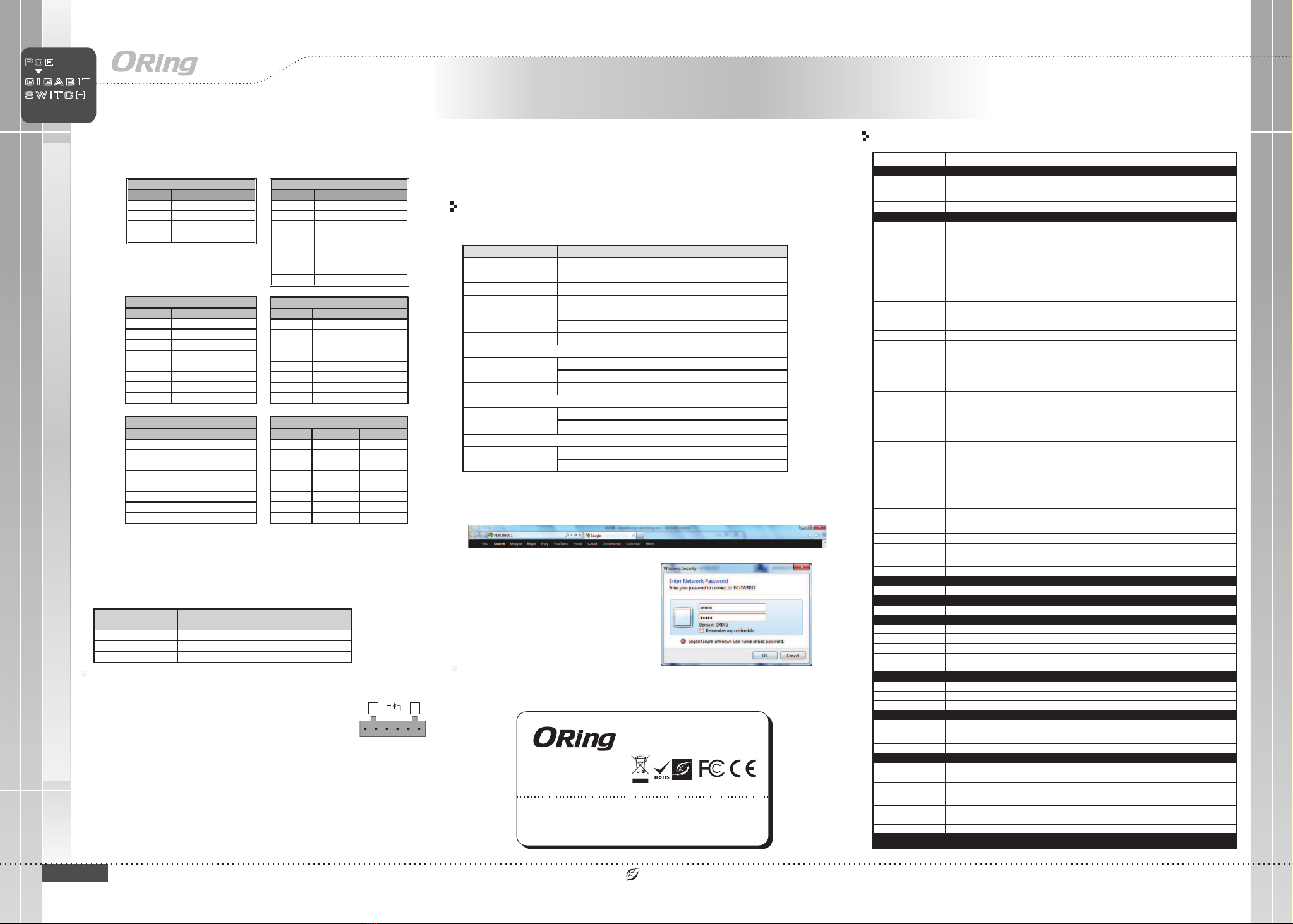
1. Launch the Internet Explorer and type in IP address of the switch. The default static IP address is
192.168.10.1
2. Log in with default user name and password
(both are ). After logging in, you shouldadmin
see the following screen. For more information
on configurations, please refer to the user
manual. For information on operating the switch
using ORing’s Open-Vision management utility,
please go to ORing website.
Follow the steps to set up the switch:
OR in g Sw it ch Model IG PS -9 82 2DGP+
Ph ys ical Ports
Te ch nology
Et herne t Stand ards
IE EE 802. 3 for 10B ase-T
IE EE 802. 3u for 10 0Base -TX and 10 0Base -FX
IE EE 802. 3ab for 1 000Ba se-T
IE EE 802. 3z for 10 00Bas e-X
IE EE 802. 3x for Fl ow cont rol
IE EE 802. 3ad for L ACP (Li nk Aggr eg ation C ontro l Proto col )
IE EE 802. 1p for CO S (Clas s of Serv ice)
IE EE 802. 1Q for VL AN Tag ging
IE EE 802. 1d for ST P (Span ning Tre e Proto col)
IE EE 802. 1w for RS TP (Rap id Span ning Tree Pro tocol )
IE EE 802. 1s for MS TP (Mul tiple S panning Tree Pr otoco l)
IE EE 802. 1x for Au thent icati on
IE EE 802. 1AB for L LDP (Li nk Laye r Disco very Pr otoco l)
IE EE 802. 3af/a t PoE spe cific ation
Po wer
Redun dant Inpu t power
Power c onsumpt ion(Typ.)
Du al DC inp uts. 50 -57VD C on 6-pi n termi na l block
19 Watt s
Ov erloa d curre nt prot ectio n Pr esent
Ph ys ical Charac teristic
En closu re IP-3 0
Di mensi on (W x D x H) 74 .3 (W) x 12 5( D) x 153. 6(H) mm ( 2.93 x 4. 92 x 6.05 i nch)
10 /100/ 1000B ase-T( X) with P.S .E.
Ports i n RJ45 Au to MDI/ MDIX
MA C Tabl e 32 K
PoE Man ageme nt
Pr iorit y Queue s 8
Pr ocess ing Sto re-an d-For war d
Sw itch Pr opert ies
Sw itchi ng late ncy: 7 us
Sw itchi ng band width : 66Gbp s
Th rough put (pa cket pe r secon d) : 49.1 Mpps@ 64 Bytes p acket
Ma x. Numb er of Availa ble VLA Ns: 409 6
VL AN ID Ran ge : VID 0 to 4 095
IG MP mult icast g roups : 64 for ea ch VLAN
Port ra te limi ting: U ser Def ine
Se curit y Fea tures
De vice Bi nding s ecuri ty feat ure
En able/ disab le port s, MAC ba se d port se curit y
Port ba sed net wo rk acce ss cont rol (80 2.1x)
VL AN (802 .1Q ) to se grega te and se cure ne tw ork traffi c
RA DIUS/ TAC ACS+ ce ntralize d passw ord man agement
SN MPv3 en crypt ed auth entic at ion and a ccess s ecuri ty
HTTPS / S SH / SS L en hance n etwor k secur ity
DO S/DDO S auto pr event ion
IP S ource G uard
So ftwar e Fea tures
Redun dant Ring ( O-Rin g) with r ecovery time l ess tha n 30ms
Qu ality o f Servi ce (802 .1p) fo r real- time tr affic
VL AN (802 .1Q) wi th VLAN t aggin g
IG MP Snoo ping
IP -base d bandw idth ma nagem en t
Ap plica tion- based Q oS mana ge ment
Port co nfigu ratio n, stat us, sta tisti cs , monit oring , secur ity
DH CP Serv er/Cl ient/ Rel ay
SM TP Clie nt
Mo dbus TC P
NT P serve r/cli ent
UP nP
Ne twork Redund ancy O- Ring, O -chai n, MRP , ST P/RST P/MST P (IEEE 8 02 .1 d/w/ s)*N OTE
PoE con figur ation
PoE Sta tus
PoE Sch eduli ng (turn o n/off t he Po E devic e)
Au to-Pi ng chec k(Reb oot PDs i f there i s no resp onses )
Weigh t (g) 10 78 g
8
2
Ju mbo fra me Up t o 10K Byt es
Weigh t (g) 7 10 g 74 0 g72 2 g 73 5 g 73 5 g 74 0 g
En vi ronmental
-4 0 to 85 C (-40 t o 185 F)
o o
St orage Tempe rat ure
-2 0 to 60 C (-14 t o140 F ) a t 2. 5G/10 G SFP
o o
-4 0 to 75 C (-40 t o 167 F) a t fu ll Giga bit
o o
Op erati ng Tem perature
5% t o 95% Non -cond ensin gOp erati ng Humi dity
Re gu latory Appr ovals
CE E MC (EN 55 024, EN 5 5032) , FCC Par t 15 B
EM C
EN 5 5024 (I EC/EN 6 1000- 4-2 (ES D) , IEC/E N 61000 -4-3 (R S),IE C/EN 61 000-4 -4 (EFT), I EC/EN 6 1000- 4-5 (Su rge), I EC/EN 610 00-4- 6 (CS),
IE C/EN 61 000-4 -8(PF MF), IEC/ EN 6100 0-4-1 1 (DIP) )
EM S
IE C6006 8-2-2 7Sh ock
IE C6006 8-2-3 1
IE C6006 8-2-6Vi brati on
EN60950-1
Sa fety
Fr ee Fa ll
MT BF
49 7728 hr s
1000Base-T MDI/MDI-X
Pin Number MDI port MDI-X port
1 BI_DA+ BI_DB+
2 BI_DA- BI_DB-
3 BI_DB+ BI_DA+
4 BI_DC+ BI_DD+
5 BI_DC- BI_DD-
6 BI_DB- BI_DA-
7 BI_DD+ BI_DC+
8 BI_DD- BI_DC-
1000Base-T RJ-45 Port
Pin Number Assignment
1 BI_DA+
2 BI_DA-
3 BI_DB+
4 BI_DC+
5 BI_DC-
6 BI_DB-
7 BI_DD+
8 BI_DD-
Rever se pola rity pr otect ion Pr esent
10/100 Base-T(X) RJ-45 Port
Pin Number Assignments
1 TD+
2 TD-
3 RD+
4 Not used
5 Not used
6 RD-
7 Not used
8 Not used
G I G A B I T
I N D U S T R I A L
S W I T C H
P o E
1G /10GB ase-X with S FP port 2
10 0/1G/ 2.5GB ase-X with S FP port
LED
Color
Status
Description
PWR Green On DC power on
PWR1 Green On DC power module 1 activated
PWR2 Green On DC power module 2 activated
R.M Green On Ring Master
Ring Green
On Ring enabled
Blinking Ring structure is broken (i.e. part of the ring is disconnected)
Fault Amber On Faulty relay (power failure or port disconnected)
10/100/1000Base-T(X) Gigabit PoE Ethernet ports
LINK/ACT Green
On Port Link/Act
Blinking Data transmitted
PoE Amber On Power supplied over Ethernet
100/1G/2.5GBase-X SFP ports
LINK/ACT Green
On Port Link/Act
Blinking Data transmitted
1G/10GBase-X SFP ports
LINK/ACT Green
On Port Link/Act
Blinking Data transmitted
Total PoE pow er budg et 240W m ax, 30W p er port
ORing Industrial Networking Corp.
Copyright© 2018 ORing
All rights reserved.
TEL: +886-2-2218-1066
FAX: +886-2-2218-1014
Website: www.oringnet.com
E-mail: support@oringnet.com
Packe t Buffe r 32 Mbits
Qo S
TOS/D iffse rv s uppor ted
Co S
Ap plica tion ba sed QoS
IP b ased ba ndwid th mana gemen t
RS -232 Se rial Co nsole P ort RS-2 32 in RJ4 5 conne ctor wi th cons ole cab le. Baud rate s ettin g: 1 15200 bps, 8, N , 1
Fa ul t contact
Relay Relay outpu t to carry ca pacit y of 1A at 24 VDC
Re se t Function
Reset B utton < 5 sec: Syste m reboo t, > 5 s ec: Fact ory def ault
EN 5 5032, C ISPR3 2, EN 610 00-3- 2, E N 61000 -3-3, F CC Pa rt 15 B cla ss A
EM I
Wa rranty
5 ye ars
*Note : This function is available by request only
IGPS-9822GDP+
IGPS-9822DGP+

Other ORiNG Switch manuals

ORiNG IGS-9084GP-FB2 User manual

ORiNG

ORiNG IGS-9084GP-FB2 User manual

ORiNG IGS-1082GP User manual

ORiNG

ORiNG IGS-1082GP User manual

ORiNG IBS-102FX Series User manual

ORiNG

ORiNG IBS-102FX Series User manual

ORiNG TRGPS-9084TG-M12X-BP2-MV User manual

ORiNG

ORiNG TRGPS-9084TG-M12X-BP2-MV User manual

ORiNG IES-2060 Series User manual

ORiNG

ORiNG IES-2060 Series User manual

ORiNG IGS-9084GP-FB2-SS User manual

ORiNG

ORiNG IGS-9084GP-FB2-SS User manual

ORiNG IGPS-9042GP-24V User manual

ORiNG

ORiNG IGPS-9042GP-24V User manual

ORiNG IES-1041FX-MM-SC User manual

ORiNG

ORiNG IES-1041FX-MM-SC User manual

ORiNG IGPS-9084GP User manual

ORiNG

ORiNG IGPS-9084GP User manual

ORiNG IGS-9848GPF User manual

ORiNG

ORiNG IGS-9848GPF User manual

ORiNG IPS-1042FX-24V Series User manual

ORiNG

ORiNG IPS-1042FX-24V Series User manual

ORiNG TPS-141TX-M12 Series User manual

ORiNG

ORiNG TPS-141TX-M12 Series User manual

ORiNG IES-3162GC Series User manual

ORiNG

ORiNG IES-3162GC Series User manual

ORiNG IES-1050A User manual

ORiNG

ORiNG IES-1050A User manual

ORiNG IES-1080A User manual

ORiNG

ORiNG IES-1080A User manual

ORiNG TES-3080-M12 Series User manual

ORiNG

ORiNG TES-3080-M12 Series User manual

ORiNG IGS-3044GC User manual

ORiNG

ORiNG IGS-3044GC User manual

ORiNG IGPS-9084GP User manual

ORiNG

ORiNG IGPS-9084GP User manual

ORiNG IGS-P9164 Series User manual

ORiNG

ORiNG IGS-P9164 Series User manual

ORiNG TGPS-9164GT-M12X-BP2-24V User manual

ORiNG

ORiNG TGPS-9164GT-M12X-BP2-24V User manual

ORiNG TPS-W9124GT-M12X-BP2 -24V-IP54 User manual

ORiNG

ORiNG TPS-W9124GT-M12X-BP2 -24V-IP54 User manual

ORiNG IPS-1080A User manual

ORiNG

ORiNG IPS-1080A User manual

ORiNG IGS-9122GPM User manual

ORiNG

ORiNG IGS-9122GPM User manual

ORiNG RGS-R9244GP+ Series User manual

ORiNG

ORiNG RGS-R9244GP+ Series User manual

Popular Switch manuals by other brands

Atlantis Land A02-F24-4G user manual

Atlantis Land

Atlantis Land A02-F24-4G user manual

Siemens SIMATIC NET RUGGEDCOM RS930W installation manual

Siemens

Siemens SIMATIC NET RUGGEDCOM RS930W installation manual

StarTech.com USB421HS instruction manual

StarTech.com

StarTech.com USB421HS instruction manual

NETGEAR GS305EP installation guide

NETGEAR

NETGEAR GS305EP installation guide

H3C S9500 Series Operation manual

H3C

H3C S9500 Series Operation manual

Wieland SNA 4043KE Translation of the original instructions

Wieland

Wieland SNA 4043KE Translation of the original instructions

HP S7500E Compliance and Safety Manual

HP

HP S7500E Compliance and Safety Manual

TRENDnet TE100-S24plus Specifications

TRENDnet

TRENDnet TE100-S24plus Specifications

Link electronics AVS-816/VHD Specification sheet

Link electronics

Link electronics AVS-816/VHD Specification sheet

PCB Piezotronics IMI SENSORS 685A09 Installation and operating manual

PCB Piezotronics

PCB Piezotronics IMI SENSORS 685A09 Installation and operating manual

HP 5130 48G 4SFP+ XI Product End-of-Life Disassembly Instructions

HP

HP 5130 48G 4SFP+ XI Product End-of-Life Disassembly Instructions

TP-Link JetStream T3700G-52TQ Cli reference guide

TP-Link

TP-Link JetStream T3700G-52TQ Cli reference guide

Johnson Controls G Series quick start guide

Johnson Controls

Johnson Controls G Series quick start guide

TechniSat GigaSwitch 9/8 installation instructions

TechniSat

TechniSat GigaSwitch 9/8 installation instructions

Supermicro SSE-F3548S user guide

Supermicro

Supermicro SSE-F3548S user guide

Westermo Lynx DSS L108-F2G-S2 EX user guide

Westermo

Westermo Lynx DSS L108-F2G-S2 EX user guide

NETGEAR FS116P - ProSafe 16 Port 10/100 Desktop... installation guide

NETGEAR

NETGEAR FS116P - ProSafe 16 Port 10/100 Desktop... installation guide

ZyXEL Communications EXTRASMART ES-1528 Support notes

ZyXEL Communications

ZyXEL Communications EXTRASMART ES-1528 Support notes

manuals.online logo
manuals.online logoBrands
  • About & Mission
  • Contact us
  • Privacy Policy
  • Terms and Conditions

Copyright 2025 Manuals.Online. All Rights Reserved.