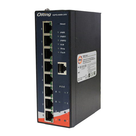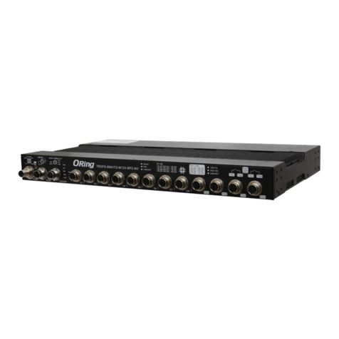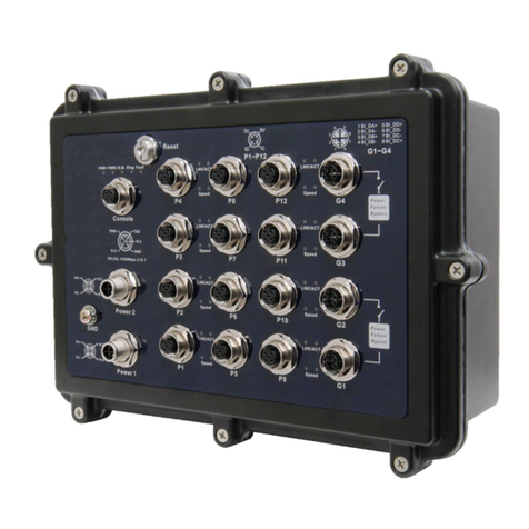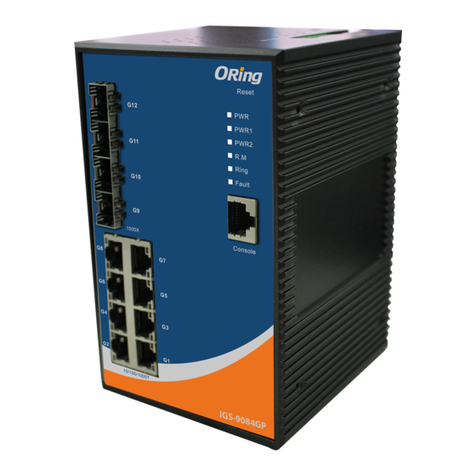
Q I G Quick Installation Guide
PRINTED ON RECYCLED PAPER
Quick Installation Guide
Version 1.1
Q I G
For pin assignments for different types of cables, please refer to the following tables.
1000 Base-T RJ-45
Pin Number Assignment
1 BI_DA+
2 BI_DA-
3 BI_DB+
4 BI_DC+
5 BI_DC-
6 BI_DB-
7 BI_DD+
8 BI_DD-
10/100 Base-T(X) MDI/MDI-X
Pin Number MDI port MDI-X port
1 TD+(transmit) RD+(receive)
2 TD-(transmit) RD-(receive)
3 RD+(receive) TD+(transmit)
4 Not used Not used
5 Not used Not used
6 RD-(receive) TD-(transmit)
7 Not used Not used
8 Not used Not used
Note: “+” and “-” signs represent the polarity of the wires that make up each
wire pair.
To connect the console port to an external management device, you need an RJ-45 to DB-
9 cable, which is also supplied in the package. Below is the console port pin assignment
information.
Console Port Pin Definition
PC (male) pin assignment RS-232 with DB9 (female) pin
assignment (RJ45-DB9 cable) RJ45 pin assignment
PIN#2 RxD PIN#2 RxD PIN#2 RxD
PIN#3 TxD PIN#3 TxD PIN#3 TxD
PIN#5 GND PIN#5 GND PIN#5 GND
10/100 Base-T(X) RJ-45
Pin Number Assignment
1 TD+
2 TD-
3 RD+
4 Not used
5 Not used
6 RD-
7 Not used
8 Not used
1000Base-T MDI/MDI-X
Pin Number MDI port MDI-X port
1 BI_DA+ BI_DB+
2 BI_DA- BI_DB-
3 BI_DB+ BI_DA+
4 BI_DC+ BI_DD+
5 BI_DC- BI_DD-
6 BI_DB- BI_DA-
7 BI_DD+ BI_DC+
8 BI_DD- BI_DC-
Resetting
To reboot the switch, press the button for 5 seconds.Reset
To restore the switch configurations back to the factory defaults, press the button for 5 seconds.Reset
Wiring
The switch supports dual redundant power supplies, Power Supply 1
(PWR1) and Power Supply 2 (PWR2). The connections for PWR1,
PWR2 and the RELAY are located on the front panel along with LAN
ports. Follow the steps below to wire power cables.
STEP 1: Insert the negative/positive wires into the V-/V+
terminals, respectively.
STEP 2: To keep the wires from pulling loose, use a small flat-
blade screwdriver to tighten the wire-clamp screws on the front
of the connector.
Power inputs
The switch provides fail open and fail close options for you to form
relay circuits based on your needs. If you want the relay device to
start operating at power failure, attach the two wires to COM and fail
close to form a close circuit, vice versa. The relay contact of the 3-pin
terminal block connector will respond to user-configured events
Relay contact
Grounding and wire routing help limit the effects of noise due to electromagnetic
interference (EMI). Run the ground connection from the ground screws to the grounding
surface prior to connecting devices.
Grounding
Configurations
After installing the switch card, the green power LED should turn on. Please
refer to the following tablet for LED indication.
1. Launch the Internet Explorer and type in IP address of the switch. The default static IP address is
192.168.10.1
2. Log in with default user name and password
(both are ). After logging in, you shouldadmin
see the following screen. For more information
on configurations, please refer to the user
manual. For information on operating the switch
using ORing’s Open-Vision management utility,
please go to ORing website.
Follow the steps below to log in and access the system
Fail
Close
Fail
Open
V-/N V+/L
Specifications
IEC 61850-3 Industrial Managed Ethernet
Switch
S W I T C H
I N D U S T R I A L
M A N A G E D
LED Color Status Description
PWR Green On DC power on
PW1 Green On DC power module 1 activated
PW2 Green On DC power module 2 activated
R.M Green On System running in Ring Master mode
On System running in Ring mode
Ring Green Blinking Ring structure is broken
Fault Amber On Faults occurs
10/100/1000Base-T(X) Fast Ethernet ports
Green On Port is connected and running at 1000Mbps
Amber On Port is connected and running at 100Mbps
LNK/ACT
Green/Amber Off Port running at 10Mbps
1000Base-X fiber ports
On Ethernet links connected
LNK/ACT Green Blinking Transmitting data
100Base-FX fiber ports
On Ethernet links connected
LNK/ACT Green Blinking Transmitting data
100/1000Base-X SFP ports
On Ethernet links connected
LNK/ACT Green Blinking Transmitting data
OR i ng Switc h Model IG S-P9164 GF-MM
Ph y sical Po rts
Fi ber Ports N u mbe r
Te c hnolog y
Et hern e t Sta n dard s
IE EE 802 . 3 for 1 0 Bas e -T
IE EE 802 . 3u fo r 1 00Ba se-TX a nd 100 Base -FX
IE EE 802 . 3z fo r 1 000B ase-X
IE EE 802 . 3ab f o r 1000 Base -T
IE EE 802 . 3ad f o r LACP ( Link A ggre gati o n Con t rol Pr otoc ol)
Po w er
Redun d ant I n put po wer
Power c onsu m ptio n(Typ.)
LV mod el : Dua l powe r inpu t s wit h 1 2~48 VDC on d ual 2 pi n term inal b l ock
HV m odel : D ual po w er in p uts wi th 85~ 264VAC/ 88~3 7 3VD C o n dua l 3 -pin t ermi nal bl ock
LV : 18Wat ts
HV : 18.5 Wa tts
Ov erlo ad cur rent p r ote c tion
Rever se pol arit y prot ecti o n
Pr esen t
Pr esen t
Ph y sical Ch aracter istic
En clos u re IP - 30
Di mens i on (W x D x H ) 11 5.0 (W ) x 159. 0 (D) x 1 5 4.0( H) mm (4 .52x 6 .26 x 6. 06 inc h )
10 /100 / 100 0 Base -T(X) Port s
in R J-45 A uto MD I/MD I X
MA C Tab le 8K
RS -232 S e ria l C onso le Po rt
Pr iori ty Que u es 8
Pr oces s ing S t ore- and - For war d
Sw itch P rope rtie s
Sw itch l aten cy: 7 us
Sw itch b andw idth : 4 0Gb p s
Ma x. Num b er of A va i labl e VLAN s: 409 5
VL AN ID Ra nge : V I D 1 to 40 9 4
IG MP mul t ica s t grou ps: 12 8 for ea ch VLA N
Port ra te li m itin g: Use r Defi ne
Se curi ty Fe atur e s
De vice B indi n g sec u rity f eatu re
En able / dis a ble po rts, M AC bas ed por t s ecu r ity
Port ba sed ne t wor k a cces s cont rol (8 02.1 x )
VL AN (80 2 .1q ) t o segr egat e and se cure n etwo r k tra ffic
Radiu s c ent rali zed pa sswo rd man a gem e nt
SN MPv3 e n cry p ted au then tica tion a n d acc e ss sec urit y
Ht tps / SS H enha nce ne twor k s ecu r ity
So ftwa re Fe atur es
ST P/RS T P/M S TP (IE EE 802 .1D/ w /s)
Redun dant R i ng (O - Ring ) with r ecov ery ti me les s than 3 0ms ov er 25 0 u nits
TOS/D iffs e rv su p port ed
Qu alit y of Ser vice ( 8 02. 1 p) for r eal- time t raf f ic
VL AN (80 2 .1Q ) w ith VL AN tag ging a nd GVR P s upp o rted
IG MP Sno o pin g f or mul tica st fil teri n g
IP -bas e d ban d widt h mana geme nt
Ap plic a tio n -bas ed QoS m anag emen t
DO S/DD O S aut o p reve nti o n
Port co nfig u rat ion, s tatu s, sta t ist i cs, mo nito ring , secu r ity
DH CP Ser ver / Cl ient s uppo r t
SM TP Cli e nt
Mo dbus T CP
NT P serv er
Ne twor k Red u ndan cy O - Ring , Open -Rin g, O-c h ain , M RP , MS TP (RS T P/S T P comp atib le), Fas t Rec over y*N OTE
RS -232 i n R J45 c o nnec tor wi th con sole c a ble . Ba u d rat e sett ing: 1 1520 0 bps , 8 , N, 1
Fi ber Ports S p eci f icat ion
Fi ber Ports S t and a rd 10 00Ba se-S X
Fi ber Mo d e Mu lti- m ode S i ngle -mod e
Fi ber Di amet e r ( m)µ62 .5/1 2 5 mµ
50 /125 mµ
Fi ber Op t ica l C onne ctor SC S C
Typica l Dist ance ( K m) 0. 55 Km 30 K m
Wave len g th (nm ) 85 0 nm 13 10 nm
Ma x. Out p ut Op t ical Powe r
(d bm) -8 d b m
Mi n. Out p ut Op t ical Powe r
(d bm) -1 5 d bm
Op tica l I npu t Pow e r-
mi nimu m ( Sen s itiv ity ) -3 4 dbm
0 db m -0 d bm
-1 8 dbm
Op tica l I npu t Pow e r-
ma ximu m ( Sat u rat ion)
Li nk Bud g et (d b ) 8. 5 db 19 d b
Weig ht (g) LV : 178 0 g
HV : 2 216 g
16
9/ 125 mµ
4
Pr oces s ing U p t o 9.6K B ytes
Fa u lt Conta ct
Relay Rela y outp ut to ca rry ca paci ty of 1A a t 24VD C on 3 p in ter m ina l b lock
10 0Bas e -FX
-4 d bm
-9 .5 dbm
Si ngle - mod e
SC
10 K m
13 10 nm
-3 d bm
-9 .5 dbm
-2 0 dbm
-3 d bm
10 .5 db
9/ 125 mµ
10 00Ba s e-L X10 0Bas e -FX
Mu lti- m ode
62 .5/1 2 5 mµ
50 /125 mµ
SC
2 Km
13 10 nm
0 db m
-3 1 dbm
7. 5 db
-1 4 dbm
-2 3.5 db m
IG S -P9164 FX-MM IG S -P9164 G F-SS IGS- P 9164FX -SS IGS-P9 164GC
Gi gabi t C omb o Por t w ith
10 /100 / 100 0 Base -T(X) a nd
10 0/10 0 0Ba s e-X SFP Port
-4
-
-
-
-
-
-
-
-
-
-
-
-
Packe t Buff er 4 Mbit s
LV : 21Wat ts
HV : 20.7 Wa tts
LV : 18Wat ts
HV : 1 8.5Wat ts
LV : 21Wat ts
HV : 1 9.3Wat ts
LV : 17Wat ts
HV : 1 8Watts
Weig ht (g) 71 0 g 74 0 g72 2 g 73 5 g 73 5 g 74 0 g
En v ironme ntal
-4 0 to 85 C (- 40 to 18 5 F)
o o
St ora g e Tem pera tur e
-4 0 to 85 C (- 40 to 18 5 F)
o o
Op era t ing Tempe rat u re
5% t o 95% No n -co n dens ingOp era t ing Hu midi ty
LV : 178 0 g
HV : 2 186 g
Re g ulator y Approv a ls
EN 5 5032 , C ISP R 32, EN 6 1000 -3-2 , EN 610 0 0-3 - 3, FCC Part 1 5B cla ss AEM I
EN 5 5024 ( I EC/ E N 6100 0-4- 2 (ESD ), IEC / EN 61 0 00-4 -3 (RS ), IEC / EN 61 0 00-4 -4 (EF T ),
IE C/EN 6 1 000 - 4-5 (S urge ), IEC / EN 61 0 00- 4 -6 (CS ), IEC /EN 61 0 00- 4 -8(P FMF) , IEC/ E N 610 0 0-4 - 11(D IP))
EM S
IE C600 6 8-2 - 27Sh ock
IE C600 6 8-2 - 31
IE C600 6 8-2 - 6Vi bra t ion
EN 6095 0 -1
Sa fety
Fr ee Fall
MT B F
LV:204 4 67
HV:2 5 0111
CE E MC (EN 5 502 4 , EN 550 32), I EC 618 50-3 , I EEE 1 6 13, EN 5015 5 (EN5 0121 - 3-2 )EM C
IGS-P9164 Series
IGS-P9164 Series
LV : 179 6 g
HV : 2 205 g
LV : 178 0 g
HV : 2 216 g
LV : 179 6 g
HV : 2 205 g
IE EE 802 . 3x fo r F low co ntro l
IE EE 802 . 1p fo r C OS (Cl ass of s ervi ce)
IE EE 802 . 1Q fo r V LAN Taggi ngIE EE 802 .1w fo r R STP ( Rapi d Span ning Tree Pr o toc o l
IE EE 802 . 1s fo r M STP (M ulti ple Sp anni n g Tre e Prot o col )
IE EE 802 . 1x fo r A uth e ntic atio n
IE EE 802 . 1AB f o r LLD P ( Link L aye r Disc over y Prot ocol )
IE C 6185 0 -3, E N 5015 5
Ot her
Wa r ranty
5 ye ars
LV:236 , 923
HV:3 0 0,46 0
LV:224681
HV:2 8 1,04 0
LV:196 , 356
HV:2 3 8,08 2
LV:299 , 365
HV:4 0 8,52 1
ORing Industrial Networking Corp.
Copyright© 2015 ORing
All rights reserved.
TEL: +886-2-2218-1066
FAX: +886-2-2218-1014
Website: www.oringnet.com
E-mail: support@oringnet.com
*Note : This function is available by request only


